


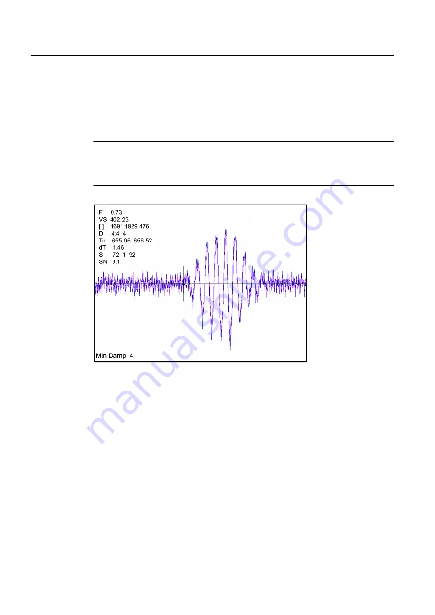
quality. The primary function of this screen is to display the digitized receive signal waveform
with the similar appearance and function of a digital oscilloscope. This screen also allows the
user to override some of the flowmeter default settings by permitting adjustment to the
measured transit time, the digital averaging and the zero crossover used in the measurement
of the up/down transit time difference. The figure shown below is a representation of the
diagnostic graph.
Note
The Test Facilities Graph Screen requires significant CPU overhead. The flowmeter should
not be left in this mode during normal operation where the Datalogger is the primary output
or during calibration work.
Figure 10-1 Test Facilities Graph Screen
Entering the Diagnostic Graph Screen
Before you can view the Diagnostic Graph Screen the flow channel must first be properly
installed and operating in a non-empty condition. If a previously installed channel is in a "Fault"
condition, but not reporting "Empty", you can still access the Graph Screen to aid in
troubleshooting the cause of the failure to measure flow.
To view the Graph Screen first enter the [Test Facilities] menu, which is a submenu of the main
[Diagnostic Data] menu.
1. Pressing the <Up/Down Arrows>, scroll to the [Graph] menu item.
2. Press the <Right Arrow> to enter the [Graph] menu and scroll to highlight the [Yes] item in
the option list.
3. Now press the <ENTER> key to access the Graph Screen.
4. To exit the Graph Screen and return to the main menu, press the <MENU> key once.
Troubleshooting
10.3 Test Facilities Graph Screen
FUP1010 IP67 Portable Flowmeter
120
Operating Instructions, 02/2010, A5E02951522A Revision 01
Summary of Contents for SITRANS FUP1010
Page 2: ......
Page 66: ......
Page 136: ......
Page 138: ......
Page 150: ......
Page 153: ...1010WP 7 21614 C ...
Page 154: ...1010WP 7 21614 C ...
Page 155: ...1010WDP 7 21614 C ...
Page 156: ...1010WDP 7 21614 C ...
Page 157: ...1010WP 8 21614 C ...
Page 158: ...1010WDP 8 21614 C ...
Page 159: ......
Page 161: ...1012FP 8 DIRECT MODE REFLECT MODE INSTALLED ON PIPE 21614 C ...
Page 162: ...1011PPS 8 TRANSDUCER PART NUMBER L H W NET WT PAIR X Z 21614 C SIZES A B C D SIZE E ...
Page 163: ...21614 C ...
Page 164: ......
Page 165: ......
Page 166: ......
Page 167: ......
Page 168: ...21614 C ...
Page 169: ...21614 C ...
Page 170: ...21614 C ...
Page 171: ...21614 C ...
Page 172: ...21614 C ...
Page 173: ...21614 C ...
Page 174: ...21614 C ...
Page 175: ...1015BC 1W 8 21614 C ...
Page 176: ......
Page 177: ...21614 C ...
Page 178: ...21614 C ...
Page 179: ...1012TP S 8 OUTLINE DIMENSIONS REFLECT MODE DIRECT MODE 1012TP S SERIES 21614 C MOUNTING TRACK ...
Page 180: ...REFLECT MODE DIRECT MODE 21614 C ...
Page 181: ...21614 C ...
Page 182: ...1015BC 1 8 21614 C ...
Page 183: ...21614 C INPUT OUTPUT TERMINALS 1015WP T10 8 ...
Page 184: ...21614 C INPUT OUTPUT TERMINALS 1015WP T26 8 ...
Page 185: ......
Page 186: ......
Page 187: ......
Page 188: ......
Page 190: ...DUAL HEAD CONFIGURATION 21614 C IN LINE CONFIGURATION FLOW ...
Page 191: ......
Page 192: ......
Page 194: ......
Page 204: ......
Page 206: ......
Page 207: ......