


SIREMOBIL
SPR2-230.812.02
Page 6 of 8
Siemens AG
System Manual
Rev. 02
02.06
CS PS SP
Medical Solutions
2 - 6
Installation of TFT displays
Protective ground wiring of the support arm
2
•
On the support arm base of the TFT Display, a short protective ground wire is attached
with stripped end. Unscrew the protective ground wire and replace it by the protective
ground wire with a length of 2m (included in the attachment kit of the TFT monitor; includ-
ed in the scope of delivery). Run the free end of the protective ground wire through the
support arm base, through the logbook compartment and then through the lateral rail of
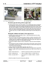
the monitor trolley to the ON/OFF assembly. Connect the wire end to a free protective
conductor bar (1/Fig. 14). Make sure that both protective ground wires make good con-
tact.
Wiring the radiation indicators of the support arm
2
•
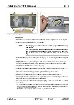
Withdraw the two radiation indicators (4/Fig. 11) after loosening the lower mounting
screws laterally from the tube.
•
One end of the cable of the additional radiation indicator (included in the delivery of the
support arm of the TFT display) is equipped with 2 free cable ends. On the other end, a
connector D50.X7 is installed. Run both cable ends in the lower tube of the support arm
through the two bores (1/Fig. 13) to the radiation indicators.
•
Connect both radiation indicators, then re-insert them in the bottom tube and retighten
them.
•
Route the cable end with the attached connector D50.X7 through the support arm base
to the logbook compartment and then through the lateral rail of the monitor trolley to the
ON/OFF assembly located below.
•
Unplug connector X4 of the ON/OFF assembly. See (2/Fig. 14).
•
Wire the Y-cable (included in the attachment kit of the TFT monitors which is part of the
delivery), together with the attached plug connectors D50.X4, D50, X4A and D50.X7, as
follows:
•
Attach the cables to the monitor trolley using cable ties.
Fig. 13 Cabling of SIEMENS displays
Fig. 14 Routing the cables
Y-cable connector D50.X4A
----- ON/OFF assembly board D50, connector D50.X4
Y-cable, coupling D50.X4
----- Cable of radiation indicator, connector D50.X4
Y-cables, coupling D50.X7
----- New support arm, radiation indicator, connector
D50.X7


