


Functions
2.18 Synchronism and Voltage Check (optional)
SIPROTEC, 7SD5, Manual
C53000-G1176-C169-5, Release date 02.2011
348
2.18
Synchronism and Voltage Check (optional)
The synchronism and voltage check function ensures, when switching a line onto a busbar, that the stability of
the network is not endangered. The voltage of the feeder to be energized is compared to that of the busbar to
check conformances in terms of magnitude, phase angle and frequency within certain tolerances. Optionally,
deenergization of the feeder can be checked before it is connected to an energized busbar (or vice versa).
The synchronism check can either be conducted only for automatic reclosure, only for manual closure (this in-
cludes also closing via control command) or in both cases. Different close permission (release) criteria can also
be programmed for automatic and manual closure.
Synchro check is also possible without external matching transformers if a power transformer is located
between the measuring points.
Closing is released for synchronous or asynchronous system conditions. In the latter case, the device deter-
mines the time for issuing the close command such that the voltages are identical the instant the breaker poles
make contact.
2.18.1
Method of Operation
General
For comparing the two voltages, the synchro check uses the voltages U
sy1
and U
sy2
. If the voltage transformers
for the protection functions (U
sy1
) are connected to the feeder side, U
sy2
has to be connected to a busbar volt-
age. If, however, the voltage transformers for the protection functions U
sy1
are connected to the busbar side,
the U
sy2
has to be connected to a feeder voltage.
U
sy2
can be any phase-to-earth or phase-to-phase voltage (see Section 2.1.2.1 margin heading Voltage Con-
nection).
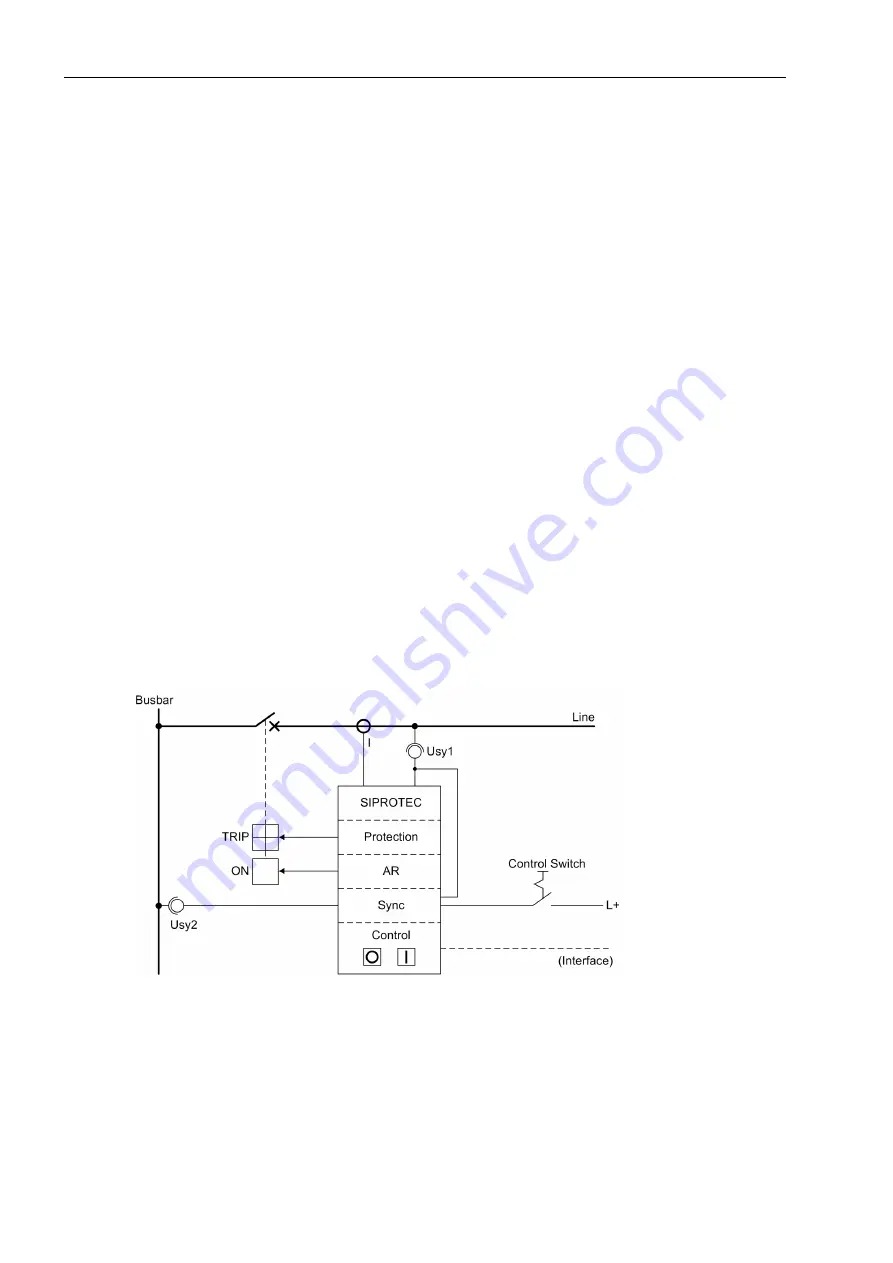
Figure 2-169
Synchronism check on closing - example
If a power transformer is located between the feeder voltage transformers and the busbar voltage transformers
(Figure 2-170), its vector group can be compensated for by the 7SD5 relay, so that no external matching trans-
formers are necessary.


