Unbalanced Load (Negative Sequence) Protection (ANSI 46)
65
7UM62 Manual
C53000-G1176-C149-3
2.10
Unbalanced Load (Negative Sequence) Protection (ANSI 46)
General
Unbalanced load protection detects unbalanced loads. The negative sequence
currents associated with unbalanced loads create reverse fields in three-phase
induction machines, which act on the rotor at double frequency. Eddy currents are
induced at the rotor surface, and local overheating of the rotor end zones and the slot
wedges begins to take place. Another effect of unbalanced loads is an overheating of
the damper winding. In addition, it may be used to detect interruptions, faults, and
polarity problems with current transformers. It is particularly useful in detecting phase-
to-ground, phase-to-phase, and double phase-to-ground faults with magnitudes lower
than the maximum load current.
2.10.1 Functional Description
Unbalanced Load
Determination
The unbalanced load protection feature of the 7UM62 relay uses filtering to calculate
the symmetrical components from the phase currents. It evaluates the negative-phase
sequence system, the negative phase-sequence current I
2
. If the negative phase-
sequence current exceeds a set threshold value, the trip timer starts. A trip command
is transmitted as soon as this trip time has expired.
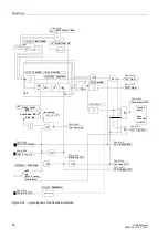
Warning stage
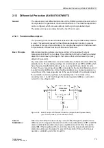
If the value of the continuously permissible, negative phase-sequence current
is
exceeded, a warning message ”
” is transmitted after a selectable time
(see Figure 2-21).
Thermal
Characteristic
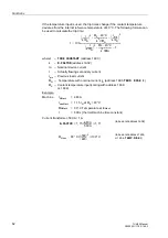
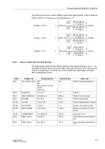
The machine manufacturers indicate the permissible unbalanced load by means of the
following formula:
The asymmetry factor depends on the machine and represents the time in seconds
during which the generator can be loaded with a 100 % unbalanced load. This factor
is typically in a range between 5 s and 30 s.
The heating up of the object to be protected is calculated in the relay as soon as the
permissible unbalanced load is exceeded. The current-time-area is calculated
constantly to ensure a correct consideration of the changing load. The thermal
characteristic is tripped as soon as the current-time-area ((I
2
/I
N
)
2
⋅
t) has reached the
K asymmetry factor.
Limitation
The model of the heating of the object to be protected is limited to a 200 % trip
temperature overrange.
Cool Down
A settable cool-down time starts as soon as the value falls below the constantly
permissible unbalanced load
. The parameter
is defined as the time
required by the thermal image to cool down from 100 % to 0 %. The cool-down time
depends on the construction type of the generator, and especially on the damper
winding. Preloading is taken into consideration when unbalanced loading occurs
during the cool-down period. The protective relay will thus trip in a shorter time.
t
zul
K
I
2
I
N
-----
è ø
æ ö
2
-------------
=
where t
perm
=maximum permissible application time of the
negative-sequence current
I
2
K
=Asymmetry factor (machine constant)
I
2
/
I
N
=Unbal. load (ratio neg. phase-sequ.
I
2
nom. cur.
I
N
)

