Thermal Overload Protection (ANSI 49)
55
7UM62 Manual
C53000-G1176-C149-3
2.9
Thermal Overload Protection (ANSI 49)
2.9.1
Functional Description
General
The thermal overload protection feature of the 7UM61 is designed to prevent
overloads from damaging the protected equipment.
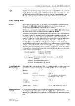
The device is capable of projecting excessive operating temperatures for the
protected equipment in accordance with a thermal model, based on the following
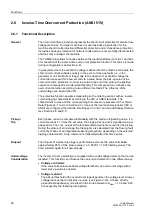
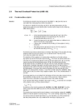
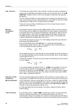
differential equation:
The thermal overload protection feature models a heat image of the equipment being
protected. Both the previous history of an overload and the heat loss to the
environment are taken into account.
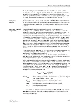
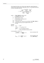
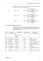
The solution of this equation is in steady-state operation an e-function whose
asymptote represents the final temperature
Θ
End
. The thermal overload protection
calculates the operating temperature of the protected equipment in per cent of the
maximum allowable operating temperature. When the calculated operating
temperature reaches a settable percentage of the maximum allowable operating
temperature, a warning message is issued to allow time for the load reduction
measures to take place. If the second temperature threshold, i.e. end temperature =
trip temperature, is reached, the protected equipment is disconnected from the
network. It is also possible, however, to set the overload protection to
Alarm only
.
If this option is set, the device only outputs an alarm, even if the end temperature is
reached.
The temperature rise is calculated from the highest of the three phase currents. Since
the calculation is based on the r.m.s. values of the currents, it also considers
harmonics which contribute to a temperature rise of the stator winding.
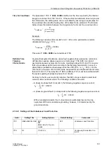
The maximum thermally permissible continuous current
I
max
is described as a multiple
of the rated current
I
N
of the protected object:
I
max
= k ·
I
N
In addition to the k factor (parameter
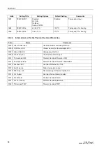
), the
τ
and the
alarm temperature
ALARM (in percent of the trip temperature
Θ
TRIP
) must be
specified.
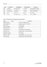
The thermal overload protection also features a current warning element
in
addition to the temperature warning stage. The current warning element may report
an overload current prematurely (before I
max
is exceeded), even if the calculated
operating temperature has not yet attained the warning or tripping levels.
d
Θ
dt
--------
1
τ
---
Θ
⋅
+
1
τ
---
I
2
⋅
1
τ
---
Θ
K
⋅
+
=
where
Θ
– Actual operating temperature expressed in per cent of the
operating temperature corresponding to the maximum
permissible operating current k ·
I
N
Θ
K
– Coolant temperature or ambient temperature as a difference to
the 40 °C reference temperature
τ
– Thermal time constant for the heating of the equipment being
protected
I
– Operating current expressed in per cent of the maximum
permissible operating current
I
max
= k ·
I
N

