A Appendix
516
7UM62 Manual
C53000-G1176-C149-3
A.9.7
Pre–Defined CFC Charts
Some CFC Charts are already supplied with the SIPROTEC
®
device:
Device and System
Logic
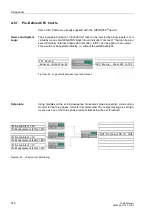
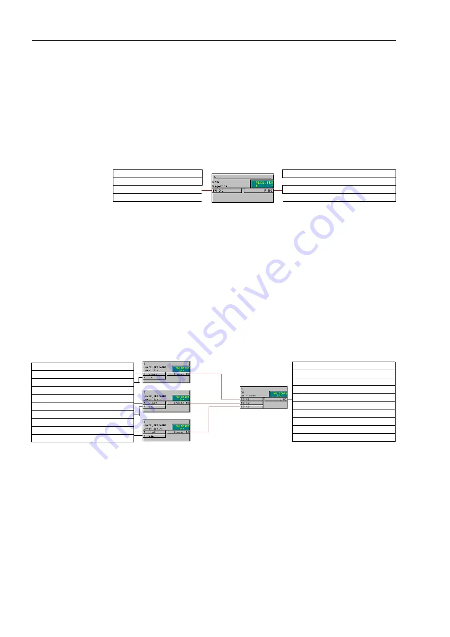
The single-point indication “
>DataStop
“ that can be injected by binary inputs is con-
verted by means of a NEGATOR block into an indication “
UnlockDT
“ that can be proc-
essed internally (internal single point indication, IntSP), and assigned to an output.
This would not be possible directly, i.e. without the additional block.
Figure A-48 Logical Link between Input and Output
Set points
Using modules on the running sequence “measured value processing”, a low current
monitor for the three phase currents is implemented. The output message is set high
as soon as one of the three phase currents falls below the set threshold
:
FigureA-49
Undercurrent Monitoring
General >DataStop SP
OUT:Device, UnlockDT IntSP
IN: Device,
IN: Set points IL< LV
IN: Measurement IL1S2 = MV
IN: Set points IL< LV
IN: Measurement IL2S2 = MV
IN: Set points IL< LV
IN: Measurement IL3S2 = MV
OUT: Set points SP. IL< OUT

