A Appendix
500
7UM62 Manual
C53000-G1176-C149-3
A.5.1
Protection Settings
The settings recommended are the same as in Section 2.29. In addition, the correction
angle (address
) and the ohmic contact resistance of the voltage
transformer must be determined during the primary tests, and set at address
.
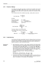
The conversion factor for the resistance (secondary – primary and vice versa) is:
Example:
Primary load resistor:
R
L
= 1250
Ω
Voltage transformer:
ü
VT
= 10.5 kV/
√
3/500 V
Ohmic divider:
ü
Divider
= 1650
Ω
/660
Ω
(5:2)
Current transformer:
ü
CT
= 1A/1A
Trip stage: primary 2 k
Ω
, secondary 66
Ω
Alarm stage: primary 5 k
Ω
, secondary 165
Ω
A.5.2
Commissioning
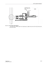
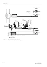
The procedure is the same as described in Section 3.3. Measurements are carried out
with the generator at standstill, and randomly selected tests are then repeated with the
generator running. The following paragraph describes the method of adjustment. A
decade resistor (0 to 10 k
Ω
) is required for the tests.
Generator at
Standstill
1. After checking the connections, a supply voltage is applied to the 20 Hz generator
and the protection device. The following parameters must be set as follows (deliv-
ery settings): address
=
0 °
and address
=
0
Ω
. In fault-free condition (R
E
infinite), read out the angle
SEF= from the oper-
ational measured values, and set the appropriate correction angle (see below).
Due to the capacitive earth current, the angle measured must be negative. If it is
not, the connection at the current input must be rotated.
The correction angle is: Phi corr = –90 Grad –(Phi measured)
Example:
Phi measured = –47 Grad, Phi corr = –90 ° + 47 ° = –43 °
The correction angle is set at address
.
2. Create a short-circuit (R
E
= 0
Ω
) in the generator starpoint, and read out the mea-
sured fault resistance (address
) from the operational measured
values. This resistance is set at address
.
FACTOR R SEF
ü
VT
ü
Divider
⋅
ü
CT
---------------------------------
=
FACTOR R SEF
10.5 kV
3 500 V
⋅
----------------------------
5
2
---
⋅
1 A
1 A
---------
------------------------------------
30.3
=
=
SEF100I>>
0 1
,
U
N.Genera tor
3
----------------------------------
R
L
ü
CT
⋅
----------------------------------
⋅
0 1
,
10.5 kV
3
--------------------
1250
Ω
1A/1A
⋅
-----------------------------------------
⋅
500 mA
≈
=
=
urrent stage:


