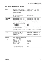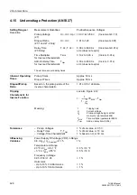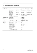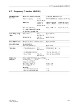
4 Technical Data
426
7UM62 Manual
C53000-G1176-C149-3
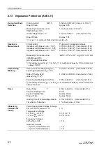
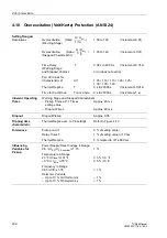
4.13
Impedance Protection (ANSI 21)
Overcurrent Fault
Detection
Pickup Current
IMP I>
0.50 A to 100.00 A
1
) (Increm. 0.05 A)
1
)
Drop-Off ratio
Approx. 0.95
Measuring Tolerances acc.to
1 % of set value or 50 mA
1
)
VDE 0435 part 303
Undervoltage Seal-In U<
10.0 V to 125.0 V
(Increments 0.1 V)
Drop-Off ratio
Approx. 1.05
1
) For I
N
= 1 A, divide all limits and increments by 5.
Impedance
Measurement
Characteristic
Polygonal, 3 independent stages
Impedance Z1 (Based on I
N
= 5 A
2
)
0.01
Ω
to 26.00
Ω
2
) (Increments 0.01
Ω
)
Impedance Z1B (Based on I
N
= 5 A
2
)
0.01
Ω
to 13.00
Ω
2
) (Increments 0.01
Ω
)
Impedance Z2 (Based on I
N
= 5 A
2
)
0.01
Ω
to 13.00
Ω
2
) (Increments 0.01
Ω
)
Measuring Tolerances as per
ê
∆
Z/Z
ê
≤
5 % for 30°
≤ ϕ
K
≤
90° or 10 m
Ω
VDE0435 part 303
with Sinusoidal Quantities
2
) Secondary values for I
N
= 5 A; for I
N
= 1 A multiply all values by 5; the increment is
always 0.01
Ω
.
Power Swing
Blocking
Difference Power Swing Polygon/
0.10
Ω
to 30.00
Ω
(Increments 0.01
Ω
)
Trip Polygon (Based onI
N
= 1 A
2
)
Rate of Change dz/dt
1.0
Ω
/s to 600.0
Ω
/s (Increments 0.1
Ω
/s)
(Based onI
N
= 1 A
2
)
Power Swing Blocking Action Time
0.00 s to 60.00 s
(Increments 0.01 s)
2
) Secondary values for I
N
= 1 A, for I
N
= 5 A devided all values by 5; the increment is
always the same.
Times
Delay Times
T
0.00 s to 60.00 s
(Increments 0.01 s)
Shortest Tripping Time
35 ms
Typical Tripping Time
Approx. 40 ms
Dropout Time
Approx. 50 ms
Holding Time of Undervoltage Seal-In
0.10 s to 60.00 s
(Increments 0.01 s)
Time Expiry Tolerances
1 % of set value or 10 ms
Influencing
Variables for
Pickup
Power Supply Direct Voltage in Range
0.8
≤
U
PS
/ U
PS nominal
≤
1.15
1 %
Temperature in Range
23 °F
≤ ϑ
amb
≤
131 °F
0.3 % / 10 °F
–5 °C
≤ ϑ
amb
≤
55 °C
0.5 % / 10 K
Frequency in Range
0.95
≤
f/f
N
≤
1.05
< 1 %
Harmonic Currents
– Up to 10 % 3rd Harmonics
< 1 %
– Up to 10 % 5th Harmonics
< 1 %

