4 Technical Data
412
7UM62 Manual
C53000-G1176-C149-3
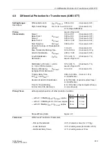
4.4
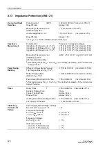
Thermal Overload Protection (ANSI 49)
Setting Ranges/
Resolutions
K-Factor per IEC 60255-8
0.10 to 4.00
(Increments 0.01)
Time Constant
τ
30 s to 32000 s
(Increments 1 s)
Extension K-Factor
k
t
- Factor
1.0 to 10.0 relative to the time constant for
when Machine Stopped
the machine running (Increments 0.1)
Thermal Alarm
Θ
Alarm
/
Θ
Trip
70 % to 100 % of the trip temperature rise
(
Θ
ALARM)
(Increments 1 %)
Current Overload
I
Alarm
0.50 A to 20.00 A
1
) (Increments 0.05 A)
1
)
Alarm (I ALARM)
Rated Temperature Rise
40 °C to 200 °C
(Increments 1 °C)
at Rated Sec. Current
104 °F to 392 °F
(Increments 1 °F)
Cooling Medium Temperature
40 °C to 300 °C
(Increments 1 °C)
for Scaling
104 °F to 572 °F
(Increments 1 °F)
Current Limiting
I
Max therm.
2.50 A to 40.00 A
1
) (Increments 0.05 A)
1
)
Emergency Time
10 s to 15000 s
(Increments 1 s)
Trip Characteristic
Curve
See also Figure 4-4
Dropout Relations
Θ
/
Θ
trip
Drops out with
Θ
Alarm
Θ
/
Θ
Alarm
Approx. 0.99
I
/
I
Alarm
Approx. 0.95
Tolerances
Referring to k ·
I
N
2 % or 50 mA
1
); 2 % class per
IEC 60255–8
Thermal Trip and Alarm Times
3 % or 1 s for I/(k ·I
N
) > 1.25;
3 % class per IEC 60255–8
Influencing
Variables Referring
to [k ·
I
N
]
Power Supply DC Voltage (U
DC
) in Range
0.8
≤
U
PS
/ U
PS nominal
≤
1.15
1 %
Temperature in Range
23 °F
≤ ϑ
amb
≤
131 °F
0.3 % / 10 °F
–5 °C
≤ ϑ
amb
≤
55 °C
0.5 % / 10 K
Frequency in Range
0.95
≤
f/f
N
≤
1.05
< 1 %
1
) For I
N
= 1 A, divide all limits and increments by 5.
t
τ
I
k
I
N
⋅
-------------
è
ø
æ
ö
2
I
pre
k
I
N
⋅
-------------
è
ø
æ
ö
2
–
I
k
I
N
⋅
-------------
è
ø
æ
ö
2
1
–
-------------------------------------------------
ln
⋅
=
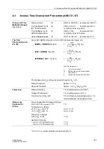
Trip Characteristic Curve
t
Trip time
τ
Temperature rise time constant
I
Load current
I
pre
Pre-load current
k
Setting factor per VDE 0435
Part 3011 and IEC 60255–8
I
N
Nominal current of the device
I
Max therm.
Current threshold up to which
the above formula is valid
Where:
for (
I
/ k
·
I
N
)
≤
I
Max therm.

