


3 Installation and Commissioning
364
7UM62 Manual
C53000-G1176-C149-3
3.4.2
Checking the Current Circuits
General
The checks of the current circuits are performed with the generator to ensure the
correct cabling, polarity, phase sequence, CT ratio etc., not in order to verify individual
protection functions in the device.
Preparation
Switch unbalanced load protection (address
) and overload protection (address
) to
Block relay
.
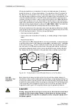
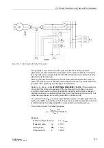
With the primary plant voltage-free and earthed, install a three-pole short-circuit bridge
which is capable of carrying rated current (e.g. earthing isolator) to the generator line-
side terminals.
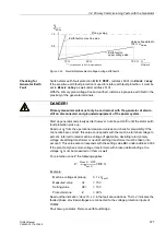
After the preparatory measures described in section 3.4.1, all current transformer
circuits (protection, measuring, metering) can be checked with the remanent
excitation.
Note on Testing
The checks of the current transformer circuits are carried out with max. 20 % of the
rated transformer current. Tests with generator currents of more than 20 % are not
normally required for the digital protective device. Operation of the generator at rated
current during commissioning may only be necessary when the short-circuit
characteristic is measured for the first time.
Absolute Current
Values
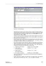
The currents are stated among the operational measured values. They are read out
from the device front panel or from the PC via the operator interface and compared
with the actual measured values. If significant deviations are found, the CT
connections are not correct.
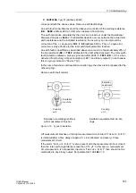
Phase Rotation
The phase rotation must conform with the configured phase sequence (address
under
Power System Data 1
); if it does not, an indication “
Fail Ph.
Seq.
“ will be output. In such a case, the allocation of phases to the measuring
quantities must be checked and corrected, if necessary. The unbalanced load
(negative sequence) can be read out under the operational measured values. It must
be practically zero. If this is not the case, check for crossed current transformer leads:
If the unbalanced load amounts to about 1/3 of the phase currents then current is
flowing in only one or in only two of the phases.
If the unbalanced load amounts to about 2/3 of the phase currents, then one current
transformer has wrong polarity.
If the unbalanced load is about the same as the phase currents, then two phases have
been crossed.
After correcting the wrong connection, the test must be repeated.
Remove short–circuit bridges.
DANGER!
Primary measurements must only be carried out with the generator at stand–
still on disconnected and grounded equipment of the power system.


