90–%–Stator Earth Fault Protection (ANSI 59N, 64G, 67G)
181
7UM62 Manual
C53000-G1176-C149-3
Determination of
the Faulty Phase
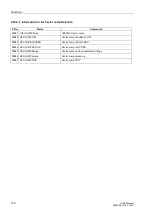
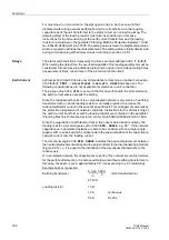
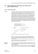
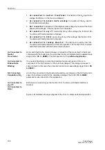
In addition to this, a supplementary function serves to determine the faulty phase. As
the phase-earth-voltage in the faulty phase is less than in the two remaining phases
and as the voltage even increases in the latter ones, the faulty phase can be
determined by determining the smallest phase-earth voltage in order to generate a
corresponding result as fault message.
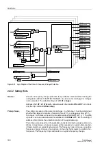
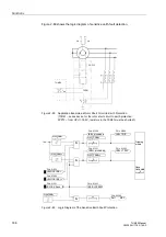
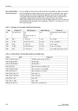
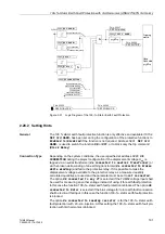
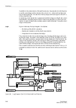
Figure 2-87
Logic Diagram of the 90%–Stator Earth Fault Protection
2.26.2 Setting Hints
General
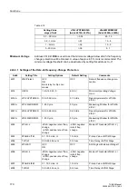
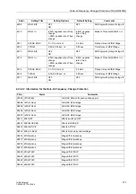
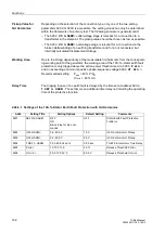
The 90% stator earth fault protection is only effective and accessible if it has been set
during the configuration of the protection functions at address
0150
=
directional; non-dir. U0
or
non-dir. U0&I0
. If
non–dir. U0
was
selected, the parameters concerning the earth current are ineffective. If one of the
options
directional
or
non–dir. U0&I0
was selected, the parameters
concerning the earth current are accessible. For machines in busbar connection, one
of the latter options must set as a differentiation between the power system earth fault
and the machine earth fault is only possible by way of the earth current. If the 90%
stator earth fault protection is used as ”earth differential protection”, address
=
non-dir. U0&I0
is selected. Set
Disabled
if the function is not
required. Address
is used to switch the function
ON
or
OFF
, or to
block only the trip command (
Block Relay
).
Displacement
Voltage
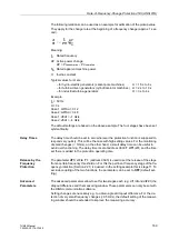
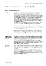
The criterion for the inception of an earth fault in the stator circuit is the occurrence of
a neutral displacement voltage. Exceeding the setting value
therefore
represents the pickup for this protection.
The setting must be chosen such that the protection does not pick up during
operational asymmetries. This is particularly important for machines in busbar
connection since all voltage asymmetries of the network affect the voltage system of
the machine. The pickup value should be at least twice the value of the operational
asymmetry. A value of 5% to 10% of the full displacement value is normal.
&
Tripping
matrix
&
&
&
&
&
FNo. 05173
FNo. 05176
OR
OR
&
FNo. 05182
FNo. 05186
FNo. 05188
FNo. 05193
FNo. 05187
non-direct. only U0
directional
non-dir. with U0 & I0
”1”
TMin
TRIP CMD
OR
&
FNo. 05194


