Reverse Power Protection (ANSI 32R)
115
7UM62 Manual
C53000-G1176-C149-3
2.15
Reverse Power Protection (ANSI 32R)
General
Reverse power protection is used to protect a turbo-generator unit in case of failure of
energy to the prime mover. In this case the synchronous generator runs as a motor
and drives the turbine, taking the required motoring energy from the network. This
condition leads to overheating of the turbine blades and must be interrupted within a
short time by tripping the network circuit-breaker. For the generator, there is the
additional risk that in case of a malfunctioning residual steam pass (defective stop
valves) after the switching off of the circuit breakers, the turbine-generator-unit is
speeded up, thus reaching an overspeed. For this reason, the system isolation should
only be performed after the detection of active power input into the machine.
2.15.1 Functional Description
Reverse Power
Determination
The reverse power protection of the7UM62 precisely calculates the active power from
the symmetrical components of the fundamental waves of the voltages and currents
by averaging the values of the last 16 cycles. The evaluation of only the positive
phase-sequence systems makes the reverse power determination independent of
current and voltage asymmetries and corresponds to the actual load of the drive end.
The calculated active power value corresponds to the overall active power. By taking
the error angles of the instrument transformers into account, the active power
component is calculated even with very high apparent powers and low power factor
(cos
ϕ
). The correction is performed by a W0 constant correction angle (see section
2.3), determined during the commissioning of the protective relay in the system. The
correction angle is set at Power System Data 1 (see Section 2.3).
Pickup Seal-In Time
To ensure that frequently occurring short pickups can cause tripping, it is possible to
perform a selectable prolongation of these pickup pulses at parameter
. Each positive edge of the pickup pulses triggers this time stage again. For a
sufficient number of pulses, the pickup signals adds up and become longer than the
time delay.
Trip Signal
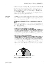
For bridging a perhaps short power input during synchronization or during power
swings caused by system faults, the trip command is delayed by a selectable time
. In case of a closed emergency tripping valve, a short delay is, however,
sufficient. By means of entering the emergency tripping valve position via a binary
input, the short time delay
becomes effective under an emergency
tripping condition. The time
is still effective as back-up stage.
It is also possible to block tripping via an external signal.
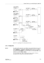
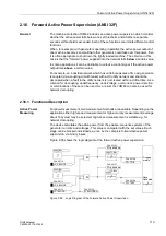
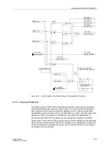
Figure 2-57 illustrates the logic diagram of the reverse power protection.

