

2 Functions
92
7ST6 Manual
E50417-G1176-C251-A3
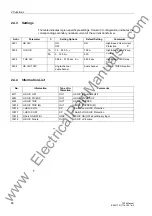
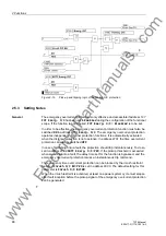
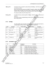
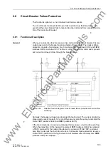
2.6.3
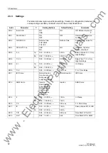
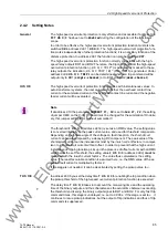
Setting Notes
The voltage protection can only operate if the parameter
O/U VOLTAGE
(address
137
)
has been set to
Enabled
during the configuration of the functional scope.
Note
For overvoltage protection it is particularly important to observe the setting hints: The
overvoltage level must never be set to less than an undervoltage level. This would put
the device immediately into a state of permanent pickup which cannot be reset by any
measured value operation. As a result, the device would remain out of service!
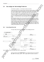
Overvoltage
The overvoltage stages can be switched
ON
or
OFF
in address
3701
OVERVOLTAGE
.
The settings of the voltage threshold and the timer values depend on the type of ap-
plication.
To detect steady-state overvoltages on long lines carrying no load, set the
U>
stage
(address
3705
) to at least 5 % above the maximum stationary phase-earth voltage ex-
pected during operation. Additionally, a high dropout to pickup ratio is required (ad-
dress
3706
U> Reset
= 0.95 = presetting). The delay time
T U>
(address
3707
)
should be a few seconds so that overvoltages with short duration may not result in trip-
ping.
The
U>>
stage (address
3702
) is provided for high overvoltages with short duration.
Here an appropriately high pickup value is set, e.g. 1.5 times the rated voltage. 0.1 s
to 0.2 s are sufficient for the time delay
T U>>
(address
3704
).
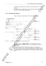
Undervoltage
The undervoltage stages can be switched
ON
or
OFF
in address
3711
UNDERVOLTAGE
. This undervoltage protection function has two stages.
The
U<
stage (address
3715
) operates with the longer set time
T U<
(address
3716
)
for minor undervoltages. It must not be set to more than the undervoltage permissible
in operation.
For greater voltage dips, the
U<<
stage (address
3712
) with the delay
T U<<
(address
3713
) takes effect.
The settings of the voltages and times depend on the application; therefore, general
setting recommendations are not possible. For load shedding, for example, the values
are often determined by a priority grading coordination chart.
In case of stability problems, the permissible undervoltages and their duration must be
observed. With induction machines undervoltages have an effect on the permissible
torque thresholds.
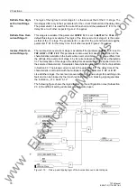
If the voltage transformers are located on the line side, the measuring voltages will be
missing when the line is disconnected. In order to ensure that the undervoltage stages
do not pick up or remain picked up in such cases, the undervoltage protection is
blocked when the current drops below a preset threshold of 0.05 I
n
. As soon as a sig-
nificant current level (I > 0.05 I
n
) is measured on the line, the line is assumed to be
energized, and the blocking of the undervoltage protection is reset.
www
. ElectricalPartManuals
. com