


2 Functions
186
7ST6 Manual
E50417-G1176-C251-A3
2.19
Auxiliary Functions
The general functions of the device are described in chapter "Additional Functions".
2.19.1 Message Processing
After the occurrence of a system fault, data regarding the response of the protective
relay and the measured quantities should be saved for future analysis. For this reason
indications are processed in three ways.
2.19.1.1 Functional Description
LED Display and
Binary Outputs
(Output Relays)
Important events and statuses are displayed using front panel LEDs. The device fur-
thermore has output relays for remote indication. Most indications and displays can be
configured differently from the delivery default settings (for information on the delivery
default setting see Appendix). The procedure is described in detail in the SIPROTEC
®
4 System Description (Order No. E50417-H1176-C151).
The output relays and the LEDs may be operated in a latched or unlatched mode
(each may be individually set).
The latched conditions are protected against loss of the auxiliary voltage. They are
reset
• On site by pressing the LED key on the relay,
• Remotely using a binary input configured for that purpose,
• Using one of the serial interfaces,
• Automatically at the beginning of a new pickup.
Condition indications should not be latched. Also, they cannot be reset until the con-
dition to be reported has been cancelled. This applies to e.g. indications from monitor-
ing functions, or the like.
A green LED displays operational readiness of the relay („RUN“), and cannot be reset.
It extinguishes if the self-check feature of the microprocessor recognizes an abnormal
occurrence, or if the auxiliary voltage fails.
When auxiliary voltage is present, but the relay has an internal malfunction, then the
red LED („ERROR“) lights up and the processor blocks the relay.
DIGSI
®
enables you to control selectively each output relay and LED of the device
and, in doing so, check the correct connection to the system. In a dialog box you can,
for instance, cause each output relay to pick up, and thus test the wiring between the
7ST6 and the station, without having to create the indications masked to it.
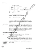
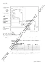
Fast Binary
Outputs (Output
Relays)
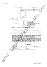
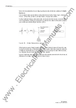
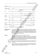
The device 7ST6 has the fast binary outputs (output relays) BO1 and BO2. These
binary outputs have extra short switching times. When used for TRIP commands,
these binary outputs allow to achieve very short trip times.
These fast trip times are possible by a parallel connection of relays and semiconductor
switches. The semiconductor switch has the task of switching the output on and off.
The relay contact carries the continuous current and opens shortly before the semi-
conductor switch drops out. This helps to avoid erosion of the relay contacts, and thus
to prolong the service life of these binary outputs. This procedure leads to a defined
contact opening delay of 8 ms.
www
. ElectricalPartManuals
. com