


2 Functions
104
7ST6 Manual
E50417-G1176-C251-A3
The reset time of the feeder protection is not relevant because the breaker failure pro-
tection itself recognizes the interruption of the current.
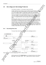
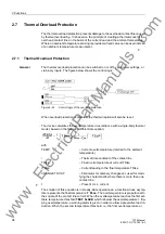
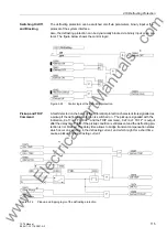
Current Flow Moni-
toring
The current detected by the device is filtered by numerical filters so that only the fun-
damental wave is evaluated.
Special features recognize the instant of current interruption. With sinusoidal currents,
the current interruption is recognized after approx. half a cycle of the power system
frequency. With aperiodic DC current components in the fault current and/or in the
current transformer secondary circuit after interruption (e.g. current transformers with
linearized core), or saturation of the current transformers caused by the DC compo-
nent in the fault current, it can take one AC cycle before the interruption of the primary
current is reliably detected.
The current is monitored and compared with the set threshold.
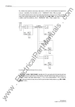
Initiation
If the breaker failure protection is intended to be initiated by further external protection
devices, it is recommended, for security reasons, to connect two starting criteria to the
device. Therefore, the trip command of the external protection should not be directly
connected to the binary input
„>BrkFail extSRC“
(FNo. 1431). For such an appli-
cation, create a CFC chart, combine in this chart the general device pickup and the
trip command of the external protection by an AND gate and wire the output of that
gate to the signal
„>BrkFail extSRC“
(FNo. 1431).
Nevertheless, it is possible to initiate the breaker failure protection in single-channel
mode should a separate release criterion not be available.
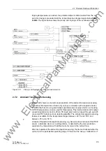
When the trip signal appears from any internal or external feeder protection and the
current flow criterion (according to Figure 2-26) is present, the breaker failure protec-
tion is initiated and the corresponding delay times are started.
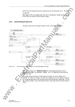
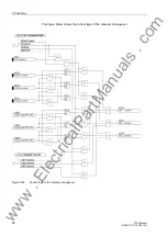
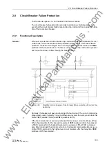
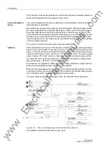
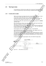
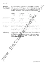
The figure below shows the control logic of the circuit breaker failure protection.
Figure 2-27
Pick-up and tripping logic of the breaker failure protection
The initiation cannot be blocked by a binary input.
www
. ElectricalPartManuals
. com