Operators Tools
7-45
7SJ63 Manual
C53000-G1140-C120-1
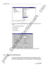
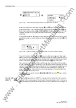
The second column is reserved for setting Input Ignore (I); the fifth for setting the out-
put block (O). The first, third, and fourth columns can only be read in this menu.
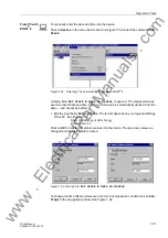
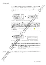
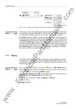
The example in Figure 7-50 shows the position for the circuit breaker (52) was tagged
(T) after the input ignore (I) was set, which means the message input was de-coupled
from the system. The output block is active (O), so the command output is also de-
coupled from the system. For the disconnect switch and the ground switch, no limita-
tions are set.
Select the desired changes using the
and
keys, and confirm with the
key.
Enter Password No. 2 (for non-interlocked switching) and acknowledge with the
key.
A safety inquiry appears: “
$UH\RXVXUH"
” If the response is “
<(6
”, and provided
the return routing is allowed, then the display gives an appropriate message.
To return to the
%5($.(56:,7&+
level, press the
key as necessary. Press the
key to return to the
0$,10(18
.
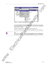
From PC Us-
ing DIGSI
®
4
For safety reasons, Status changes are only possible locally using the keypad on the
front panel of the device. Status changes are not possible in DIGSI
®
4.
7.3.4
Interlocking
Operating equipment such as circuit breakers, circuit switchers and ground switches
can be subject to interlocking conditions. These conditions can be viewed at the de-
vice under the menu item
,17(5/2&.
; however, the conditions cannot be changed.
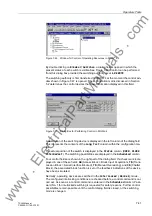
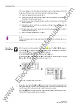
The Interlock display has an object table similar to the one described for Set Status.
The table provides the set interlocking conditions, which prevent, or could prevent, a
local control operation. Letters identify the interlocking conditions. The meanings of
the letters are:
•
L
Local/Remote (Switching Authority),
•
S
Equipment is subject to System Interlocking (in Substation Controller). Com-
mands entered locally are sent to the central computer or controller,
•
Z
Zone controlled (Field- or Bay-Interlocking),
•
P
Check switch position (test actual vs. scheduled),
•
B
Blocking by picked-up protection elements,
•
–
Non-Interlocked.
From PC with
DIGSI
®
4
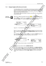
With a device ready for operation, first press the
key. The
0$,10(18
appears.
Using the
key, select the menu item
&RQWURO
and move to editing the control func-
tions with the
key. The selection
&21752/
appears.
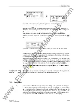
Select the item
,QWHUORFN
with the
key and switch to the next selection using the
key. The selection
,17(5/2&.
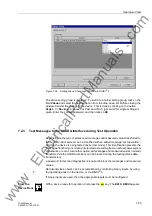
appears. See Figure 7-51.
ENTER
ENTER
MENU
:
:
MENU
www
. ElectricalPartManuals
. com

