Mounting and Commissioning
3.1 Mounting and Connections
SIPROTEC, 7SC805, Manual
C53000-G1140-C380-1, Release date 05.2014
77
3.1.2.2
Current Terminal Connections
Stop Elements and Cable Cross-Sections
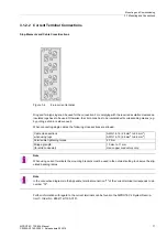
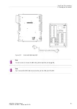
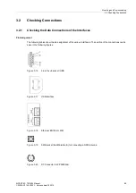
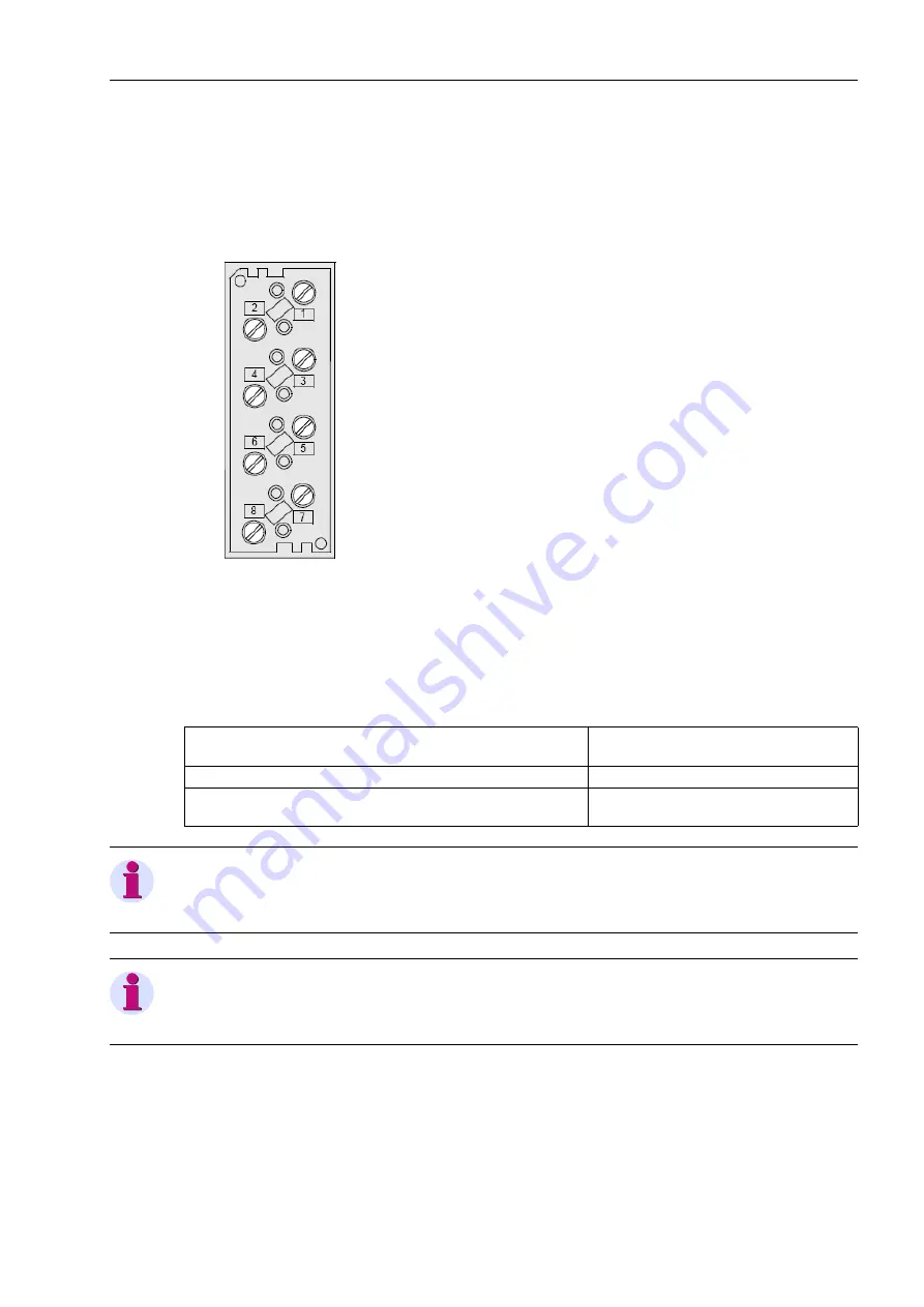
Figure 3-4
8-pin current terminal
Ring and fork-type lugs can be used for the connection. For complying with the required insulation clearances,
insulated lugs have to be used. Otherwise, the crimp zone has to be insulated with corresponding means (e.g.
by pulling a shrink-on sleeve over).
When connecting single cables, the following cross-sections are allowed:
Note
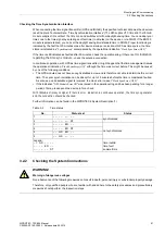
When using current terminals, the mounting brackets must be used in the outmost setting to observe the stip-
ulated bending radius.
Note
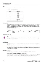
In the connection diagrams in the Appendix, terminal connection "1" of the current terminal corresponds to pin
number "72".
Further information with regard to the current terminals can be found in the SIPROTEC 4 System Descrip-
tion/1/, Order No. E50417-H1100-C151.
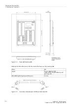
Cable cross-sections:
when using lugs
AWG 14-12 (2.6 mm
2
to 3.3 mm
2
)
AWG 14-10 (2.6 mm
2
to 6.6 mm
2
)
Permissible tightening torque
2.7 Nm
Stripping length:
(for solid conductor)
10 mm to 11 mm
Use copper conductors only.

