


Installation and Commissioning
8-29
7SA522 Manual
C53000-G1176-C119-2
voltage is not allocated. Check whether this is the required state, alternatively check
the binary input "
" if necessary (FNo.
).
q
Close the VT mcb of the busbar voltage is to be closed again.
q
Open the circuit breaker.
q
The program
=
<HV
(address
1R
(address
) is set for the synchro-check.
q
A request measurement for synchro-check is initiated via binary input (FNo.
"
". The synchronism check must release closing (message "
", FNo.
).
If not, check all voltage connections and the corresponding parameters again care-
fully as described in section 6.1.1.
q
Open the VT mcb of the feeder voltage.
q
Via binary input (FNo.
”) initiate the measuring request. No
close release is given.
q
Close the VT mcb of the busbar voltage again.
Addresses
to
must be restored as they were changed for the test. If the
routing of the LEDs or signal relays was changed for the test, this must also be re-
stored.
8.3.4
Polarity Check for Earth Fault Protection and for the Current Measuring
Input I
4
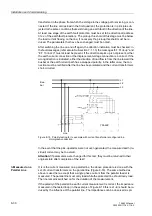
If the standard connection of the device is used whereby the current measuring input
I
4
is connected in the star-point of the set of current transformers (refer also to the con-
nection circuit diagram in the Appendix, Figure 1-9), then the correct polarity of the
earth current path in general will result automatically.
If however the current I
4
is derived from a separate summation CT (e.g. a core balance
CT) or from a different point of measurement, e.g. transformer star-point current or
earth current of a parallel line, an additional polarity check with this current is neces-
sary.
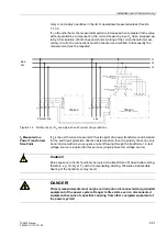
The test is done with a disconnected trip circuit and primary load current. It must be
noted that during all simulations that do not exactly correspond with situations that
may occur in practice, the non-symmetry of measured values may cause the meas-
ured value monitoring to pick up. This must therefore be ignored during such tests.
I
4
Measured on the
Protected Line
To generate a displacement voltage, the e–n winding of one phase in the voltage
transformer set (e.g. L1) is bypassed (refer to Figure 8-15). If no connection on the e–
n windings of the voltage transformer is available, the corresponding phase is open
circuited on the secondary side. Via the current path only the current from the current
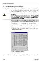
DANGER!
Working on measurement transformers requires the highest precautions!
Short-circuit the secondary side of the current transformers before any current
connections to the device are opened!
Summary of Contents for siprotec 7SA522
Page 20: ...7SA522 Manual C53000 G1176 C119 2 ...
Page 64: ...7SA522 Manual C53000 G1176 C119 2 ...
Page 89: ...SIPROTEC 4 Devices 4 25 7SA522 Manual C53000 G1176 C119 2 Figure 4 20 CFC Logic example ...
Page 408: ...7SA522 Manual C53000 G1176 C119 2 ...
Page 456: ...7SA522 Manual C53000 G1176 C119 2 ...
Page 516: ...7SA522 Manual C53000 G1176 C119 2 ...
Page 620: ...Appendix B 48 ...