Hardware and Connections
2-18
7SA522 Manual
C53000-G1176-C119-2
2.2.2
Screw terminal connections
Terminal Blocks
All connections to the device are by means of two-tier screw terminals located at the
top and bottom of the surface mounting housing. For the housing size
1
/
2
there are 100
such terminals and for the housing size
1
/
1
there are 200 such terminals.
The plug connection module in the device for the current terminals automatically short-
circuits the current transformer circuits when the modules are withdrawn. This does
not reduce necessary care that must be taken when working on the current transform-
er secondary circuits.
Connections to
Terminals
Solid conductor or stranded wire with lugs can be used.
The following specifications must be observed:
Direct cable connections: solid or stranded conductor with connector sleeve
conductor with cross-section of 0.5 mm
2
to 7 mm
2
(AWG 20 to 9).
Use copper wires only!
Maximum tightening torque: 1.2 Nm (0.9 ft-lb or 10.6 ft-in)).
2.2.3
Connections to Optical Communication Interfaces
Optical
Communication
Interfaces
Optical communication interfaces may be 1- to 4-channel. The ports are supplied with
caps to protect the optical components against dust or other contaminants. The caps
can be removed by turning them 90° to the left.
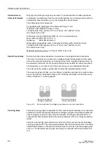
A maximum of two fibre optic channels are located in each inclined housing. In the
case of device versions with 1 and 2 channels, the inclined housing is located at the
bottom side of the device. With device versions having up to a maximum of 4 fitted
optical channels, there is a second inclined housing mounted to the top side of the de-
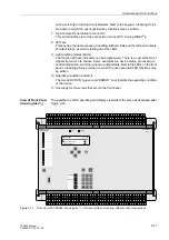
vice (refer to Figure 2-18). If no inclined housing is fitted a cover plate is mounted in-
stead. Unused fibre optic connections are replaced by plastic studs.
Connections to
Optical
Communication
Interfaces
Optical connector type:
ST–connector
Fibre type:
Multimode graded-index (“G”) optical fibre
G50/125 µm,
G62.5/125 µm,
G100/140 µm
Wavelength:
λ
= 820 nm (approximately)
Allowable bending radius:
For indoor cable
r
min
= 5 cm (2 in)
For outdoor cable r
min
= 20 cm (8 in)
Laser class 1 (acc. EN 60 825–1) is achieved with fibre type G50/125 µm and
G62.5/125 µm.
Summary of Contents for siprotec 7SA522
Page 20: ...7SA522 Manual C53000 G1176 C119 2 ...
Page 64: ...7SA522 Manual C53000 G1176 C119 2 ...
Page 89: ...SIPROTEC 4 Devices 4 25 7SA522 Manual C53000 G1176 C119 2 Figure 4 20 CFC Logic example ...
Page 408: ...7SA522 Manual C53000 G1176 C119 2 ...
Page 456: ...7SA522 Manual C53000 G1176 C119 2 ...
Page 516: ...7SA522 Manual C53000 G1176 C119 2 ...
Page 620: ...Appendix B 48 ...


