Hardware and Connections
2-4
7SA522 Manual
C53000-G1176-C119-2
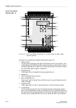
8. LED key
This key has the dual purpose of resetting latched LEDs and the latched contacts
of output relays, as well as testing all of the LEDs.
9. Light emitting diodes (LEDs)
The function of these indicators can be programmed. There is a vast selection of
signals from which to choose. Some examples are device status, processing or
control information, and binary input or output status. Next to the LEDs on the front
panel, a labeling strip is provided on which the user-specified LED functions may
be written.
10. Operating condition indicators
The two LEDs “RUN” (green) and “ERROR” (red) indicate the operating condition
of the device.
11.Coverings for the screws that secure the front panel.
View of Front Panel
(Housing Size
1
/
1
)
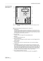
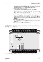
The significance of the operating and display elements is the same as explained after
Figure 2-1.
Figure 2-2
Front view of a 7SA522, housing size
1
/
1
, for panel flush mounting or cubicle
mounting
SIEMENS
SIPROTEC
1
2
6
3
+/-
0
5
4
7
8
9
7SA522
RUN
ERROR
MENU
ESC
LED
ENTER
F4
F1
F2
F3
0$,10(18
$QQXQFLDWLRQ
0HDVXUHPHQW
Summary of Contents for siprotec 7SA522
Page 20: ...7SA522 Manual C53000 G1176 C119 2 ...
Page 64: ...7SA522 Manual C53000 G1176 C119 2 ...
Page 89: ...SIPROTEC 4 Devices 4 25 7SA522 Manual C53000 G1176 C119 2 Figure 4 20 CFC Logic example ...
Page 408: ...7SA522 Manual C53000 G1176 C119 2 ...
Page 456: ...7SA522 Manual C53000 G1176 C119 2 ...
Page 516: ...7SA522 Manual C53000 G1176 C119 2 ...
Page 620: ...Appendix B 48 ...


