Functions
6-170
7SA522 Manual
C53000-G1176-C119-2
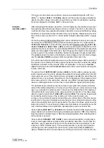
remote end has also closed. This delay must therefore be added to the dead time for
consideration of the network stability.
Configuration of
the automatic
reclosure function
This configuration concerns the interaction between the protection and supplementary
functions of the device and the automatic reclosure function. The selection of functions
of the device which are to start the automatic reclosure circuit and which are not to, is
made here.
In the 7SA522 this concerns:
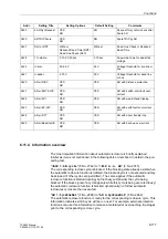
Address
, i.e. with distance protection,
Address
, i.e. with high–current fast tripping,
Address
, i.e. with transfer trip and remote trip,
Address
, i.e. with externally coupled trip command,
Address
, i.e. with time-overcurrent protection.
For the functions which are to start the automatic reclosure circuit, the corresponding
address is set to
<HV
, for the others to
1R
. The other functions (overload protection)
cannot start the automatic reclosure because reclosure is of little use here.
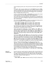
Forced three-pole
coupling
If reclosure is blocked during the dead time of a single-pole cycle without a three-pole
trip command having been given, the line remains tripped single pole. With address
it is possible to determine that the tripping logic of the device
issues a three-pole trip command in this case (pole discrepancy prevention for the CB
poles). Set this address to
<HV
if the CB can be tripped single-pole and has no pole
discrepancy protection itself. Nevertheless, the device pre-empts the pole disrepancy
protection of the CB poles because the forced three-pole coupling of the device is im-
mediately activated as soon as the reclosure is blocked following a single-pole trip or
if the CB auxiliary contacts indicate a non plausible switching state (see also section
6.11.1 under subtitle "Processing the circuit breaker auxiliary contacts“). The forced
three-pole coupling is also activated when only three-pole cycles are allowed but a sin-
gle-pole trip is signalled externally via a binary input.
The forced three pole coupling is unnecessary if only a common three-pole control of
the CB is possible.
Dead line check/
reduced dead time
Under address
the dead line check or the reduced dead time function can be
activated. Either the one or the other can be used as the two options are contradictory.
The voltage transformers must be connected to the line side of the circuit breaker if
either of these modes is to be used. If this is not the case or if neither of the two func-
tions is used, set
. If the adaptive dead time is used (see
below), the parameters mentioned here are omitted because the adaptive dead time
implies the properties of the reduced dead time.
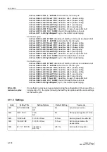
=
means that the dead line check of the line voltage is used. This
only enables reclosure after it becomes apparent that the line is dead. In this case, the
setting
under address
determines the limit voltage, Phase–Earth,be-
low which the line is considered to be definitely dead (disconnected). The setting is
appied in Volts secondary. This value can be entered as a primary value when param-
etrizing with a PC and DIGSI
®
4. Address
suring time available for determining the no-voltage condition. Address
is irrele-
vant here.
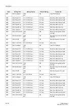
=
5'7
means that the reduced dead time is used. This is described in
detail in section 6.11.1 under subtitle "Reduced dead time (RDT)“, page 159. In this
case the setting under address
determines the limit voltage, Phase–
Earth,above which the line is considered to be fault-free. It must be set smaller than
the smallest expected operating voltage. The setting is applied in Volts secondary.
Summary of Contents for siprotec 7SA522
Page 20: ...7SA522 Manual C53000 G1176 C119 2 ...
Page 64: ...7SA522 Manual C53000 G1176 C119 2 ...
Page 89: ...SIPROTEC 4 Devices 4 25 7SA522 Manual C53000 G1176 C119 2 Figure 4 20 CFC Logic example ...
Page 408: ...7SA522 Manual C53000 G1176 C119 2 ...
Page 456: ...7SA522 Manual C53000 G1176 C119 2 ...
Page 516: ...7SA522 Manual C53000 G1176 C119 2 ...
Page 620: ...Appendix B 48 ...

