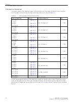


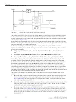


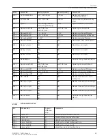


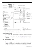

MC SYNCHR
Released at synchronism, that is when the critical
values
MC maxVolt.Diff
,
MC maxFreq.Diff
,
MC
maxAngleDiff
are within the set limits.
MC Usy1< Usy2>
Released if measuring point Usy1< is de-energized
and the measuring point Usy2> is energized.
MC Usy1> Usy2<
Released if measuring point Usy1> is energized and
the measuring point Usy2< is de-energized.
MC Usy1< Usy2<
Released if measuring point Usy1< is de-energized
and the measuring point Usy2< is also de-energized.
MC OVERRIDE
Released without any check.
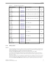
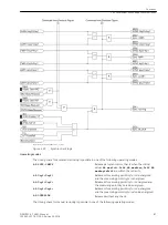
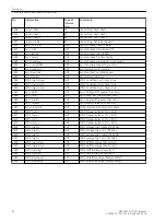
Each of these conditions can be enabled or disabled individually; combinations are also possible, e.g. release if
AR Usy1<Usy2>
or
AR Usy1>Usy2<
are fulfilled). Combination of
AR OVERRIDE
with other parameters is,
of course, not reasonable (see also
).
The release conditions can be configured individually for automatic reclosing or for manual closing or for
closing via control commands. For example, manual closing and closing via control command can be allowed
in cases of synchronism or dead line, while, before an automatic reclose attempt dead line conditions are only
checked at one line end and after the automatic reclose attempt only synchronism at the other end.
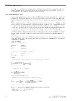
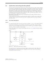
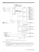
Non-energized switching
To release the closing command to couple a dead overhead line to a live busbar, the following conditions are
checked:
•
Is the feeder voltage below the set value
Dead Volt. Thr.
?
•
Is the busbar voltage above the setting value
Live Volt. Thr.
, but below the maximum voltage
Umax
?
•
Is the frequency within the permitted operating range f
N
± 3 Hz?
After successful check the closing command is released.
Corresponding conditions apply when switching a live line onto a dead busbar or a dead line onto a dead
busbar.
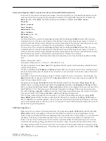
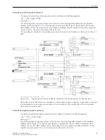
Closing under synchronous system conditions
Before releasing a closing command under synchronous conditions, the following conditions are checked:
•
Is the busbar voltage above the setting value
Live Volt. Thr.
, but below the maximum voltage
Umax
?
•
Is the feeder voltage above the setting value
Live Volt. Thr.
but below the maximum voltage
Umax
?
•
Is the voltage difference |U
sy1
– U
sy2
| within the permissible tolerance
AR maxVolt.Diff
or
MC
maxVolt.Diff
?
•
Are the two frequencies f
sy1
and f
sy2
within the permitted operating range f
N
± 3 Hz?
•
Does the frequency difference |f
sy1
– f
sy2
| lie within the permissible tolerance
AR maxFreq.Diff
or
MC
maxFreq.Diff
?
•
Is the angle difference |φ
sy1
– φ
sy2
| within the permissible tolerance
AR maxAngleDiff
or
MC maxAn-
gleDiff
?
To check whether these conditions are fulfilled for a certain minimum time, you can set this minimum time as
T SYNC-STAB
Checking the synchronism conditions can also be confined to the a maximum monitoring time
T-SYN. DURATION
. This implies that the conditions must be fulfilled within the time
T-SYN. DURATION
for
the duration of
T SYNC-STAB
. If this is the case, the closing release is granted.
Functions
2.4 Synchronism and voltage check (optional)
88
SIPROTEC 4, 7VK61, Manual
C53000-G1176-C159-5, Edition 05.2018
Summary of Contents for SIPROTEC 4 7VK61
Page 8: ...8 SIPROTEC 4 7VK61 Manual C53000 G1176 C159 5 Edition 05 2018 ...
Page 10: ...10 SIPROTEC 4 7VK61 Manual C53000 G1176 C159 5 Edition 05 2018 ...
Page 16: ...16 SIPROTEC 4 7VK61 Manual C53000 G1176 C159 5 Edition 05 2018 ...
Page 176: ...176 SIPROTEC 4 7VK61 Manual C53000 G1176 C159 5 Edition 05 2018 ...
Page 224: ...224 SIPROTEC 4 7VK61 Manual C53000 G1176 C159 5 Edition 05 2018 ...
Page 264: ...264 SIPROTEC 4 7VK61 Manual C53000 G1176 C159 5 Edition 05 2018 ...
Page 270: ...270 SIPROTEC 4 7VK61 Manual C53000 G1176 C159 5 Edition 05 2018 ...
Page 276: ...276 SIPROTEC 4 7VK61 Manual C53000 G1176 C159 5 Edition 05 2018 ...
Page 346: ...346 SIPROTEC 4 7VK61 Manual C53000 G1176 C159 5 Edition 05 2018 ...


