


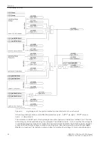


The different versions of the FIR-Filter (Finite Impulse Response), takeover a central function which is charac-
terised by a defined impulse response, linear phase and high stability. The filter was so designed that DC
components and higher frequency disturbance signals which differ from the rated frequency, are effectively
suppressed. In addition the "decimation filter" incorporated in the analog digital converter is of help in disturb-
ance signal suppression.
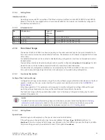
The following table gives an overview of measurement conversion.
Table 2-1
Overview of the two measurement procedures
Measurement procedure 1
Measurement procedure 2
Voltage
Measurement
With two orthogonal FIR filters (filter
length 1 cycle and frequency correction)
the real and imaginary components of the
voltage vector are established. This
produces the amplitude value (funda-
mental harmonic).
With two orthogonal FIR filters (filter
length 1.25 cycles implemented using two
displaced lowpass filters and frequency
correction) the real and imaginary compo-
nents of the voltage vector are estab-
lished. This produces the amplitude value
(fundamental harmonic).
Frequency
Measurement
The frequency is calculated using a special
filter procedure with series 60th order
bandpass (3 cycles filter). The measure-
ment procedure tolerates deviations from
the rated frequency.
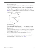
The frequency is determined by an angle
difference measurement of the voltage
vector(delta interval three cycles). Devia-
tions from the rated frequency are
corrected accordingly.
Angle
Measurement
The arctan of the angle is established
using the frequency corrected vector of
the above FIR filter.
The arctan of the angle is established
using the frequency corrected vector of
the above FIR filter.
Connection
“asynchronous
power systems”
The connection condition is the angle,
with the current measure value Δf the
closure time of the breaker is converted to
an angle, if the measured angle agrees
with the “CB angle” the closure command
results.
Connection condition is the time, using Δf
Δα is converted to a time; if the time
proportional to the angle agrees with the
CB closure time, the closure command
results.
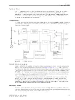
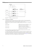
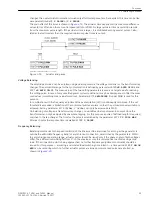
Monitoring Procedure
In
in addition essential monitoring procedures are shown which are explained in the following. The
measure values are fed to 2 analog/digital converters (ADC) where the second ADC processes value rotated
by180° (U1; U2). The monitoring procedures checke the entire transformer circuits including internal acquisi-
tion and storage, for plausibility, and block the measurement procedures in the event of deviations.
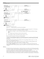
With the Sampled value monitoring for each sampled value the following equations are processed for the
two voltages U1 and U2:
I u1(k) + u1(k) I ≤ Δu
I u2(k) + u2(k) I ≤ Δu
If an admissible voltage Δu is exceeded, an error must be present in measured value acquisition or storage
(voltage transformer, ADC, memory). If this fault occurs several times, a disturbance indication (25037
Sync
Fail Ch U1
; 25038
Sync Fail Ch U2
) is created for each channel and the synchronizing functions are
blocked.
This channel monitoring is only used with configuration as a parallel switching device. This monitoring is not
provide for single-phase synchrocheck applications.
The Jump monitoring (data continuity monitoring) is intended to register a flipping of higher value bits which
can falsely produce a large sampled value and thus lead to amplitude and angle measurement errors. Possible
causes are: ADC errors, memory errors or induced disturbances (EMC). Consecutive sampled values are moni-
tored in accordance with the following relationship.
I ua(k) – ua(k–1) I ≤ Δu
max
I ub(k) – ub(k–1) I ≤ Δu
max
I ud(k) – ud(k–1) I =Δu
max
2.2.1.4
Functions
2.2 Paralleling Functions
40
SIPROTEC 4, 7VE61 and 7VE63, Manual
C53000-G1176-C163-3, Edition 10.2017
Summary of Contents for SIPROTEC 4 7VE61
Page 8: ...8 SIPROTEC 4 7VE61 and 7VE63 Manual C53000 G1176 C163 3 Edition 10 2017 ...
Page 24: ...24 SIPROTEC 4 7VE61 and 7VE63 Manual C53000 G1176 C163 3 Edition 10 2017 ...
Page 142: ...142 SIPROTEC 4 7VE61 and 7VE63 Manual C53000 G1176 C163 3 Edition 10 2017 ...
Page 192: ...192 SIPROTEC 4 7VE61 and 7VE63 Manual C53000 G1176 C163 3 Edition 10 2017 ...
Page 222: ...222 SIPROTEC 4 7VE61 and 7VE63 Manual C53000 G1176 C163 3 Edition 10 2017 ...
Page 230: ...230 SIPROTEC 4 7VE61 and 7VE63 Manual C53000 G1176 C163 3 Edition 10 2017 ...
Page 256: ...256 SIPROTEC 4 7VE61 and 7VE63 Manual C53000 G1176 C163 3 Edition 10 2017 ...
Page 314: ...314 SIPROTEC 4 7VE61 and 7VE63 Manual C53000 G1176 C163 3 Edition 10 2017 ...
Page 316: ...316 SIPROTEC 4 7VE61 and 7VE63 Manual C53000 G1176 C163 3 Edition 10 2017 ...
Page 330: ...330 SIPROTEC 4 7VE61 and 7VE63 Manual C53000 G1176 C163 3 Edition 10 2017 ...


