Auxiliary Functions
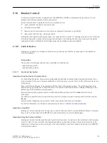
Message Processing
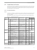
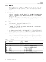
After the occurrence of a system fault, information regarding the response of the protective relay and the
measured values is important for a detailed analysis. An information processing function in the device takes
care of this.
The procedure for allocating information is described in the SIPROTEC 4 System Description.
Applications
•
LEDs and Binary Outputs
•
Information via Display Field of the Device or via PC
•
Information to a Control Center
LEDs and Binary Outputs (Output Relays)
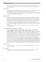
Important events and conditions are indicated via LEDs on the front cover. The device furthermore has output
relays for remote signaling. Most of the messages and indications can be allocated, i.e. configured differently
from the delivery condition. The Appendix of this manual deals in detail with the delivery condition and the
allocation options.
The output relays and LEDs may be operated in a latched or unlatched mode (each may be set individually).
The latched conditions are protected against loss of the auxiliary voltage. They are reset
•
locally by pressing the LED key on the relay,
•
remotely using a binary input configured for that purpose,
•
via one of the serial interfaces,
•
automatically at the beginning of a new pickup.
Condition messages should not be latched. They also cannot be reset until the criterion to be reported is
canceled. This applies, for example, to messages from monitoring functions or similar.
A green LED indicates operational readiness of the relay (“RUN”); it cannot be reset. It goes out if the self-check
feature of the microprocessor recognizes an abnormal occurrence, or if the auxiliary voltage is lost.
When auxiliary voltage is present but the relay has an internal malfunction, then the red LED (“ERROR”) lights
up and the relay is blocked.
Information via Display Field or PC
Using the front PC interface or the port B at the bottom, a personal computer can be connected, to which the
information can be sent.
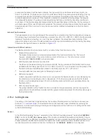
The relay is equipped with several event buffers for operational messages, circuit-breaker statistics, etc., which
are protected against loss of the auxiliary voltage by a buffer battery. These messages can be output on the
display field at any time via the keypad or transferred to a PC via the operator interface. Readout of messages
during operation is described in detail in the SIPROTEC 4 System Description.
Classification of Messages
The messages are categorized as follows:
•
Operational messages (event log); messages generated while the device is operating: Information
regarding the status of device functions, measured data, power system data, control command logs etc.
•
Fault messages (trip log): messages from the last 8 network faults that were processed by the device.
•
Messages of statistics; they include a counter for the trip commands initiated by the device and possibly
reclose commands as well as values of interrupted currents and accumulated fault currents.
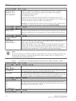
A complete list of all message and output functions that can be generated by the device with the maximum
functional scope can be found in the appendix. All functions are associated with an information number
2.17
2.17.1
2.17.1.1
2.17.1.2
Functions
2.17 Auxiliary Functions
SIPROTEC 4, 7SD80, Manual
181
E50417-G1100-C474-A2, Edition 02.2018
Summary of Contents for SIPROTEC 4 7SD80
Page 8: ...8 SIPROTEC 4 7SD80 Manual E50417 G1100 C474 A2 Edition 02 2018 ...
Page 10: ...10 SIPROTEC 4 7SD80 Manual E50417 G1100 C474 A2 Edition 02 2018 ...
Page 18: ...18 SIPROTEC 4 7SD80 Manual E50417 G1100 C474 A2 Edition 02 2018 ...
Page 248: ...248 SIPROTEC 4 7SD80 Manual E50417 G1100 C474 A2 Edition 02 2018 ...
Page 298: ...298 SIPROTEC 4 7SD80 Manual E50417 G1100 C474 A2 Edition 02 2018 ...
Page 312: ...312 SIPROTEC 4 7SD80 Manual E50417 G1100 C474 A2 Edition 02 2018 ...
Page 322: ...322 SIPROTEC 4 7SD80 Manual E50417 G1100 C474 A2 Edition 02 2018 ...
Page 400: ...400 SIPROTEC 4 7SD80 Manual E50417 G1100 C474 A2 Edition 02 2018 ...
Page 402: ...402 SIPROTEC 4 7SD80 Manual E50417 G1100 C474 A2 Edition 02 2018 ...

