06.03
10.5 Axes and spindles
10-330
Siemens AG, 2003. All rights reserved
SINUMERIK 840Di Manual (HBI) – 06.03 Edition
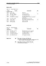
Table 10-32
Indexing axes: Interface signals
DB number
Bit, Byte
Name
Ref.
Axis/spindle-specific
Signals from axis/spindle to PLC
31,...
60.4, 60.5
Referenced/synchronized 1, referenced/synchronized 2
R1
31,...
76.6
Indexing axis in position
/FB/
Description of Functions, Extended Functions,
T1 Indexing Axes
10.5.13 Parameter sets of axis/spindle
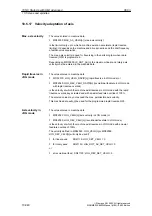
Per machine axis, 6 parameter sets are available. They are used as follows:
with one axis:
for accommodation of the own dynamic response to another machine axis,
e.g. when tapping or thread cutting.
with a spindle:
quick accommodation of the position controller to modified properties of the
machine during operation, e.g. when switching the gearbox.
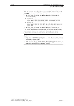
The following applies to axes:
For a machine axis that is not involved in tapping or thread cutting, the 1st
set of parameters (index=0) is active in all cases.
All further sets of parameters need not be taken into account.
For machine axes involved in tapping or thread cutting, the parameter sets
corresponding to the current gear stage of the spindle becomes active.
All sets of parameters corresponding to the gear stages of the spindle have
to be parameterized.
The following applies to spindles:
With spindles, each gear stage is assigned a parameter set of its own. The
parameter set is selected from the PLC using the interface signal DB31, ...
DBX16.0 – 16.2 (actual gear stage).
All sets of parameters corresponding to the gear stages of the spindle have
to be parameterized.
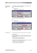
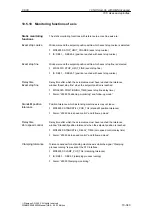
For example, in HMI Advanced, the active parameter set of a machine axis is
displayed in the control area “DIAGNOSIS” in the screen form “Service Axis”.
Interface signals
References
Tapping, thread
cutting
10 NC Start-Up with HMI Advanced

