


Velocities, Setpoint/Actual Value Systems, Closed-Loop Control (G2)
7.3 Setpoint/actual-value system
Turning, Milling, Nibbling
Function Manual, 11/2012, 6FC5397-1CP10-5BA0
123
7.3
Setpoint/actual-value system
7.3.1
General
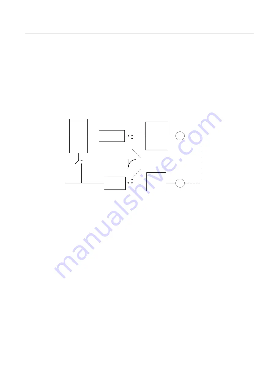
Block diagram
A control loop with the following structure can be configured for every closed-loop controlled
axis/spindle:
0'
(1&B7<3( 6,08/$7,21
0'
&75/287B7<3( 6,08/$7,21
$FWXDO
YDOXH
URXWLQJ
(QFRGHU
0RWRU
,63RVLWLRQPHDVXULQJ
V\VWHP
*
$FWXDOYDOXH
SURFHVVLQJ
0
6SHHG
VHWSRLQW
URXWLQJ
6SHHGVHWSRLQW
RXWSXW
&ORVHGOR
RSFRQWURO
Figure 7-1
Block diagram of a control loop
Setpoint output
A setpoint can be output for each axis/spindle. The setpoint output at the setting device is
done digitally or, in the case of analog spindles 10 V unidirectionally or bidirectionally.
Simulation axes
The speed control loop of an axis can be simulated for test purposes. The axis "traverses"
with a following error, similar to a real axis.
A simulation axis is defined by setting MD30130 CTRLOUT_TYPE[n] (setpoint output type)
and MD30240 ENC_TYPE[n] (actual-value acquisition type) to "0".
As soon as the standard machine data has been loaded, the axes become simulation axes.
The setpoint and actual value can be set to the reference point value with reference point
approach.
MD30350 SIMU_AX_VDI_OUTPUT (output of axis signals for simulation axes) can be set to
define whether axis-specific interface signals are output to the PLC during the simulation
process.