Accessories
9.7 Output reactor
Power Module PM240-2
Hardware Installation Manual, 01/2017, A5E33294624B AE
127
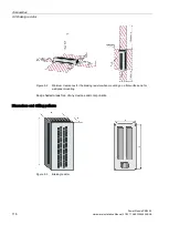
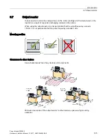
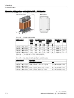
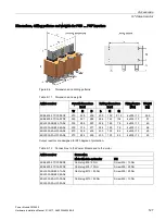
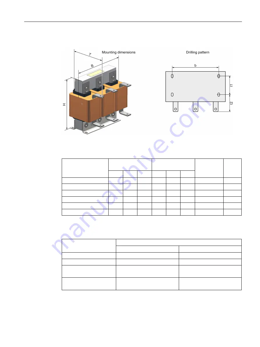
Dimensions, drilling patterns and weights for FSD … FSF inverters
Figure 9-6
Dimensions and drilling patterns
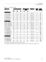
Table 9- 11 Dimensions and weights
Article number
Overall dimensions
[mm]
Drilling dimensions
[mm]
Fixing/torque
[Nm]
Weight
[kg]
W
H
D
b
t1
t2
6SE6400-3TC07-5ED0
270
248
209
200
102
91.5
4 x M8 / 13
26.5
6SE6400-3TC14-5FD0
350
321
288
264
140
134
4 x M8 / 13
57
6SL3000-2BE32-1AA0
300
285
257
224
165
78
4 x M8 / 13
60
6SL3000-2BE32-6AA0
300
315
277
224
185
78
4 x M8 / 13
66
6SL3000-2AH31-0AA0
270
248
200
200
103
82
4 x M8 / 13
25
6SL3000-2AH31-5AA0
270
248
200
200
103
82
4 x M8 / 13
26
Output reactors are designed to IP20 degree of protection.
Table 9- 12 Connections to the Power Module and to the motor
Article number
Connection
Motor Module and motor
PE
6SE6400-3TC07-5ED0
Cable lug M6 / 6 Nm
Screw M6 / 10 Nm
6SE6400-3TC14-5FD0
Cable lug M8 / 13 Nm
Screw M8 / 25 Nm
6SL3000-2BE32-1AA0
6SL3000-2BE32-6AA0
Cable lug M10 / 50 Nm
Screw M8 / 25 Nm
6SL3000-2AH31-0AA0
6SL3000-2AH31-5AA0
Cable lug M10 / 50 Nm
Screw M6 / 10 Nm
Summary of Contents for SINAMICS PM240-2
Page 1: ......
Page 2: ......
Page 8: ...Table of contents Power Module PM240 2 8 Hardware Installation Manual 01 2017 A5E33294624B AE ...
Page 104: ...Spare parts Power Module PM240 2 104 Hardware Installation Manual 01 2017 A5E33294624B AE ...
Page 143: ......
Page 144: ......

