Overview
4.4 Menu structure
Intelligent Operating Panel 2 (IOP-2)
16
Operating Instructions, 06/2020, FW V2.6, A5E39549448B AH
4.4
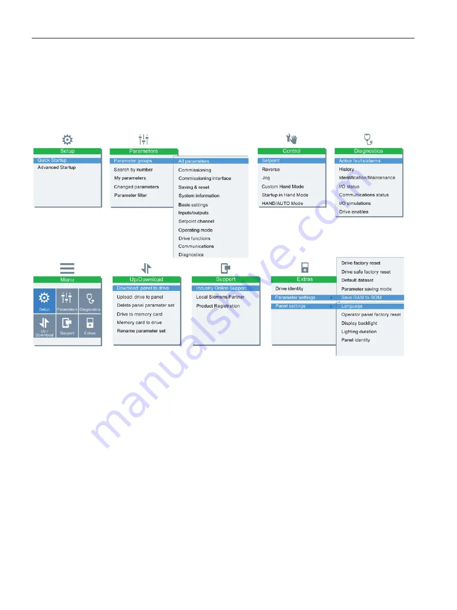
Menu structure
The Menu structure of the IOP-2 is shown in the figure below.
Figure 4-3
IOP-2 menu structure
Page 1: ......
Page 2: ......
Page 3: ...rating Instructions Edition 06 2020 Firmware IOP 2 V2 6 06 2020 FW V2 6 A5E39549448B AH Changes in this manual 1 Fundamental safety instructions 2 Safety notes 3 Overview 4 Installation 5 Setup Menu 6 Control menu 7 Menu 8 Options 9 Technical data 10 ...
Page 4: ...ted only by personnel qualified for the specific task in accordance with the relevant documentation in particular its warning notices and safety instructions Qualified personnel are those who based on their training and experience are capable of identifying risks and avoiding potential hazards when working with these products systems Proper use of Siemens products Note the following WARNING Siemen...
Page 5: ...ion 11 4 2 Layout and functions 12 4 3 Screen icons 14 4 4 Menu structure 16 5 Installation 17 5 1 Fitting the IOP 2 17 5 2 Initial set up 18 5 3 Changing the Status screens 22 5 4 User definable labels on status screen 24 5 5 Upgrading the IOP 2 firmware 25 6 Setup Menu 27 6 1 Example Setups 28 6 1 1 Quick Startup with the IOP 2 31 6 1 2 Advanced Startup with the IOP 2 35 7 Control menu 39 7 1 Se...
Page 6: ...structions 06 2020 FW V2 6 A5E39549448B AH 8 3 Parameters 51 8 4 Up Download 54 8 5 Support 59 8 6 Customer parameter sets 61 8 7 Extras Menu 65 9 Options 71 9 1 Door mounting kit 71 9 2 Hand held device 74 10 Technical data 79 10 1 Technical specifications 79 Index 81 ...
Page 7: ...2 6 A5E39549448B AH 5 Changes in this manual 1 Changes to this manual Edition 06 2020 Listed below and the specific changes that have been incorporated in this new version of the IOP 2 Operating Instructions Changes New topic Command Line Interface CLI Up Download Page 54 ...
Page 8: ...Changes in this manual Intelligent Operating Panel 2 IOP 2 6 Operating Instructions 06 2020 FW V2 6 A5E39549448B AH ...
Page 9: ...measures e g emergency stop or emergency off 2 2 Warranty and liability for application examples Application examples are not binding and do not claim to be complete regarding configuration equipment or any eventuality which may arise Application examples do not represent specific customer solutions but are only intended to provide support for typical tasks As the user you yourself are responsible...
Page 10: ...r supported and failure to apply the latest updates may increase customer s exposure to cyber threats To stay informed about product updates subscribe to the Siemens Industrial Security RSS Feed under https www siemens com industrialsecurity https new siemens com global en products services cert html Subscriptions Further information is provided on the Internet Industrial Security Configuration Ma...
Page 11: ...en the command source is switched to Hand and all OFF and RUN commands are given via the IOP 2 buttons When in the Hand mode if the IOP 2 is removed from the converter the converter will stop within a few seconds of the IOP 2 being removed Before removing the IOP 2 ensure that the IOP 2 is placed in AUTO mode and receiving its command source from the PLC WARNING Risk of death due to software manip...
Page 12: ... with Safety Integrated will be overwritten for example by the IOP 2 of another drive without Safety Integrated Incorrect parameter assignment can cause machines to malfunction which can lead to injuries or death Ensure that only the IOP 2 that belongs to the respective converter is used Ensure that only trained or authorized personnel have access to the enclosures cabinets or electrical equipment...
Page 13: ...erface It has been designed to automatically recognize the following devices from the SINAMICS range SINAMICS G120 CU230P 2 SINAMICS G120 CU240B 2 SINAMICS G120 CU240E 2 SINAMICS G120 CU250S 2 SINAMICS G120C SINAMICS G120D 2 CU240D 2 SINAMICS G120D 2 CU250D 2 SINAMICS ET 200pro FC 2 SINAMICS G110D SINAMICS G110M SINAMICS G120X SINAMICS G120XA Denotes Control Units that require the IOP 2 Hand Held ...
Page 14: ...ssion processes of Quick Startup and Advanced Startup Drives with GP firmware prior to version 3 4 are not fully supported by the IOP 2 The actual menu structure and functionality of the IOP 2 will be influenced by the following factors The software version and type of Control Unit to which the IOP 2 is fitted The firmware and software version of the IOP 2 The selected functional group filtering o...
Page 15: ...ed by pressing the HAND AUTO key In HAND mode the converter is started the converter status icon starts turning Notes For Control Units with firmware versions less than 4 0 When running in AUTO mode HAND mode cannot be selected unless the converter is stopped For Control Units with firmware versions 4 0 or greater When running in AUTO mode HAND mode can be selected and the motor will continue to r...
Page 16: ...IOP 2 will enter the DEMO mode To lock the IOP 2 keypad press ESC and INFO simultaneously for 3 seconds or more To unlock the keypad press ESC and INFO simultaneously for 3 seconds or more DEMO mode DEMO mode allows the IOP 2 to be used for demonstration purposes without affecting the converter to which it is connected Menus can be navigated and functions selected but all communications with the c...
Page 17: ...ESM Essential Services Mode Battery condition The battery status is only shown when the IOP 2 Hand held kit is used Screen faults and alarm indicators When a fault or an alarm is active on the converter the top label on the screen will turn red The top label will remain red until the fault or warning has been acknowledged or rectified Figure 4 2 Fault and alarm notifications Use of screen colours ...
Page 18: ...ructure Intelligent Operating Panel 2 IOP 2 16 Operating Instructions 06 2020 FW V2 6 A5E39549448B AH 4 4 Menu structure Overview The Menu structure of the IOP 2 is shown in the figure below Figure 4 3 IOP 2 menu structure ...
Page 19: ...2 to the converter Control Unit the following procedure should be performed 1 Place the bottom edge of the IOP 2 casing into the lower recess of the Control Unit housing 2 Push the IOP 2 forward until the top fastening clicks into place on the Control Unit housing To use the IOP 2 with a decentralized drive for example an ET200pro FC 2 an IOP 2 Handheld kit is required and an optical cable The IOP...
Page 20: ...h the IOP 2 is fitted has a real time clock The IOP 2 will then display the choice between Quick Startup or Advanced Startup Quick Startup is the recommended selection The procedure is outlined below Note Saving and cloning of the IOP 2 configuration data All changes made to an IOP 2 configuration included all saved parameter sets are stored in the IOP 2 file structure in the user folder To copy c...
Page 21: ...nformation on Firmware upgrades please see Upgrading the IOP 2 firmware Page 25 The status screen can be reconfigured to show a number of different views and types of values these can be configured using the Status Screen Wizard in the Extras menu see Extras Menu Page 65 Language selection The IOP 2 on first start up will display the language screen for the user to select their required language s...
Page 22: ...livered with the IOP 2 Setting time and date When the IOP 2 is first fitted to a Control Unit which has a real time clock it will automatically display the time and date screen Should you wish to manually set the time on the IOP 2 the following actions should be performed Select Menu Select Extras Select Panel settings Select Time and date settings Set the Time and date settings Set time and date ...
Page 23: ... the following actions should be performed Select Menu Select Extras Select Panel settings Select Lighting duration Select Lighting duration time Press and hold down ESC for Status Screen Note Screen will flash when an active fault condition exists When an active fault condition exists on the IOP 2 if no key has been pressed for more than one minute then the screen will start to flash on and off T...
Page 24: ...e automatically changed to the Low setting after 60 seconds from the last key press to extend the life of the display When any key is pressed the backlight setting will automatically return to the user setting 5 3 Changing the Status screens Changing the status screens The status screens of the IOP 2 can show three different styles of screens Bar graph view This shows the selected data on up to tw...
Page 25: ... modify the data that is displayed on the status screen the following procedure should be performed 1 Use the UP key to enter the status screen selection mode 2 Press OK to edit the displayed data 3 Use the arrow keys to navigate around the screen until the data you wish to change is highlighted Press OK to edit the highlighted data 4 Press OK to edit the parameter to be displayed 5 Select the new...
Page 26: ...fying the IOP 2 status screens 5 4 User definable labels on status screen User definable labels User defined labels allow the user to customize the labels that appear on the status screen of the IOP 2 There are a maximum of four labels that can be defined and they are located on the IOP 2 in the cps folder The IOP 2 must be connected to the PC via the USB connection and in Mass ...
Page 27: ...mes relate to the area of the status where they will appear Simply selected the file you wish to use as a label open it with a text editor change the name and then save it back to the same location in the IOP 2 file system If the file name itself is changed the IOP 2 will not recognize the label An example of the status screen with new label names using all four text files is shown in the figure b...
Page 28: ...pproximate 6 minutes 9 When the copying has been completed wait approximate 5 seconds before disconnecting the IOP 2 from the USB port The new firmware is now available on the IOP 2 and you can now connect the IOP 2 to a SINAMICS G inverter 10 When you turn on the SINAMICS G inverter the IOP 2 will automatically upgrade Note English language is mandatory The English language file is essential to t...
Page 29: ...rox 8 to 30 s and accelerate the motor to the setpoint speed This action must be taken into account when the Quick Startup procedure has been completed to ensure that the first ON RUN command when given for your application does not produce an unpredicted or unsafe effect on personnel equipment or premises WARNING Safe and stable state of the converter During the setup of the converter it is essen...
Page 30: ... take place including the observation and adherence of all local national and international safety regulations required for the user s application and all devices utilized by the user s application Quick Startup Advanced Startup Quick Startup The Quick Startup procedure is all the user needs to setup the converter in quickly and easily The Quick Startup allows the user to configure the following c...
Page 31: ...ity to setup the dynamics settings of the converter Optimization This allows the user to optimize the converter for technological applications and ensure that the correct motor data will be used I O Setup This allows the user to configure the Input and Output settings of the converter The I O configuration is pre assigned using macros so that no further settings are necessary Fieldbus Setup This a...
Page 32: ...ng of the drive WARNING Motor data identification motor ID When selecting motor data identification motor ID with subsequent ramp up to the setpoint speed p1900 11 or 12 12 standard setting based on SINAMICS Firmware V4 7 SP3 with Standard Drive Control and Dynamic Drive Control the motor is upon the first Power ON command directly accelerated to the setpoint speed following a short delay time cau...
Page 33: ...uctions in the Installation sections of the converter Operating Instructions Macro source selection During the Quick Startup process the user will be presented with a list of preset macros that determine the configuration of converter Every Control Unit Operating Instructions contain a list of the macros that are specific for that particular Control Unit and show the wiring configurations for each...
Page 34: ...6 A5E39549448B AH Select Setup Select Quick Startup Select Factory Reset yes or no Factory Reset begins Select Motor Standard Select mains frequency and units Select Motor Type Select Input Mode Enter Motor Data or Motor Code Select Supply Voltage Enter Supply Voltage from rating label Select Motor Current ...
Page 35: ... AH 33 Enter Motor Current from rating label Select Motor Power Enter Motor Power from rating label Select Motor Speed Enter Motor Speed from rating label Select Motor Voltage Enter Motor Voltage from rating label Select Motor Frequency Enter Motor Frequency Select Min Freq Enter the required Min Freq Select Max Freq ...
Page 36: ... A5E39549448B AH Enter the required Max Freq Select Ramp up Time Enter required Ramp up Time Select Ramp down Time Enter required Ramp down Time Select I O Setup Select the required Macro Save the Settings Saving Settings in progress Settings have been saved Motor ID ran on next ON command Setup up completed ...
Page 37: ... setup process the data can be saved to the converter s memory Setup Icons The setup process uses a number of very important icons to indicate the status of the settings A description of the various icons is given below The settings for the function at the default settings The settings for the function have been changed and saved The settings for the function must be checked to ensure the safety s...
Page 38: ...tor Panel IOP 2 Factory Reset This function resets all the parameters to their factory default settings Any safety parameters that have been modified will not be reset It is recommended that you reset to the factory settings before commissioning the converter Hardware Options This screen gives the user the opportunity to setup the converter options for example an Output Filter or a Braking Resisto...
Page 39: ... the user the opportunity to setup the dynamics settings of the motor for example minimum and maximum motor speed ramp up and ramp down timings and OFF 3 ramp down time Optimisation This screen makes is possible to optimise the converter for the technological applications and ensures that the correct motor data will be used I O Setup This screen allows the I O configuration to be defined The I O c...
Page 40: ...Control Unit that is being used The user can setup their own list of functions using the Adjust function list feature which allows functions to be added to or removed from the displayed list A grey tick is displayed beside the functions that have not been configured using the IOP 2 and when a function has been configured using the IOP 2 a green tick is shown beside the function in the list If a fu...
Page 41: ... menu 7 Overview The Control menu allows the user to change the following settings in real time Setpoint Reverse Jog Custom Hand mode Startup in Hand mode Hand Auto disable The control menu is accessed from the menu at the bottom centre of the Status screen as shown below Figure 7 1 Select Control Menu ...
Page 42: ...ch wheel to set the Setpoint Note Setpoint in Hertz Hz for SINAMICS CU230P 2 The setpoint screen by default displays the motor speed as a percentage of the total possible speed of the motor This behaviour changes for the SINAMICS CU230P 2 where the default setpoint value is displayed in Hertz Hz 7 2 Reverse Setting Reverse The function of the reverse command is to set the direction of rotation of ...
Page 43: ...s P1058 Jog right and P1059 Jog left are set to the required frequencies for the users application The default jogging setpoint for both parameters is 5 Hz 150 rpm When the Jog left and Jog right Jog1 and Jog 2 have been set it is necessary to do a long press of the INFO key to select the other jog mode 7 4 Custom Hand mode Overview The custom hand mode allows the user to setup a command source an...
Page 44: ...enable Bit5 Reserved Bit5 Continue ramp function generator Bit6 Reserved Bit6 Setpoint enable Bit7 Alarms menu acknowledge all faults Bit7 Acknowledge faults Bit8 Jog 1 Control menu Bit8 Jog 1 Bit9 Jog 2 Control menu Bit9 Jog 2 Bit10 Reserved Bit10 Control by PLC Bit11 Change direction Control menu Bit11 Direction of rotating reversed Bit12 Reserved Bit12 Speed control enable Bit13 Reserved Bit13 ...
Page 45: ...cted the IOP 2 will return to the Setpoint selection screen then press ESC for 3 secs to return to the status screen In this example the converter is now setup to receive the ON OFF1 command from Digital Input 0 DI0 and the speed setpoint from Analog Input 0 AI0 from the controlling PLC 7 5 Startup in Hand mode Overview Startup in Hand mode allows the converter under the control of the Intelligent...
Page 46: ...n The converter after a power cycle will automatically startup in Hand mode but the attached motor will not run until the run command is given by the buttons on the IOP 2 7 6 HAND AUTO disable Overview The HAND AUTO disable function disables the HAND AUTO key on the Intelligent Operator Panel IOP 2 and pressing the key will not produce any action by the IOP 2 An example of setting up the Hand Auto...
Page 47: ...ow disabled and local control of the IOP 2 cannot be activated by the HAND AUTO button In this example the converter is now setup to receive the HAND AUTO command from Digital Input 1 DI1 Note Power cycle required to complete the HAND AUTO disable function When the HAND AUTO disable function is initiated the function will not become active until a power cycle of the IOP 2 has been performed When t...
Page 48: ...Control menu 7 6 HAND AUTO disable Intelligent Operating Panel 2 IOP 2 46 Operating Instructions 06 2020 FW V2 6 A5E39549448B AH ...
Page 49: ...rictions to SharePoints databases etc by user management with for example the use of credentials The Menu is selected from the five menu options at the bottom of the IOP 2 screen When the Menu option is selected the following functions are displayed Wizards Parameters Diagnostic Up Download Extras By sliding your finger around the Sensor Control Field or using the arrow keys the required function ...
Page 50: ... Each fault and alarm can be selected and by pressing the INFO key or the OK key an explanation of the fault or alarm will be displayed History When this option is selected the screen will display a list of all previous faults and alarms with the time that they occurred Each fault and alarm can be selected and by pressing the INFO key or the OK key an explanation of the fault or alarm will be disp...
Page 51: ...tal inputs are displayed Communications status This option displays the status of the fieldbus interface and the details of the settings for the data exchange for example status words and control word lengths In the example shown opposite the status of the fieldbus communications is shown I O simulation WARNING Loss of control of the converter If the converter is started using the I O simulation a...
Page 52: ...s in the terminals A simulation can be overridden and made high The screen presents the following options I O Three I Os can be simulated two digital and one analog Status this indicates the real time status of the input or output If the square is shaded then the input or output signal is present This is a read only section of the screen Control this column of the screen displays the present statu...
Page 53: ...he Sensor Control Field in a fast motion A large blue box will appear on the screen showing the current parameter number with each scroll the number will increase by 100 When the user stops scrolling the parameter number nearest to the number displayed will be selected Parameter groups All parameters This option allows the user access to the individual parameters of the converter The default filte...
Page 54: ...nfiguration of the inputs and outputs and if necessary access the parameters directly to modify their values Setpoint channels This option allows the user to display and modify the setpoint parameters Operating mode This option allows the user to display and modify the operating mode parameters Drive functions This option allows the user direct access to the parameters regarding the drive function...
Page 55: ...s list to another IOP 2 When a My Parameters list is created it saves the lists in the config bin file on the IOP 2 To copy the config bin the following procedure should be performed 1 Connect the IOP 2 via the USB to your PC the IOP 2 will enter Mass Storage mode 2 Navigate to the config folder shown in the screenshot 3 Copy the config bin file to a suitable location on your PC 4 Disconnect the I...
Page 56: ... transfer is not interrupted and the process is allowed to be completed If the process is interrupted it is possible that the data could be corrupted and the system may behave in an unexpected manner Should an interruption of the transfer process occur then it is highly recommended that a factory reset of the converter is performed prior to any further parameterization or giving the converter cont...
Page 57: ... be overwritten for example by the IOP 2 of another drive without Safety Integrated Incorrect parameter assignment can cause machines to malfunction which can lead to injuries or death Ensure that only the IOP 2 that belongs to the respective converter is used Ensure that only trained or authorized personnel have access to the enclosures cabinets or electrical equipment rooms Command Line Interfac...
Page 58: ...arameter on each line Read a parameter rdpw param index value timeout ms rdpw 10 0 0 5000 Wait 5 seconds for p10 to go back to 0 Read a BICO parameter rdpw param index param index timeout ms wrp 840 0 722 5 1 Allows 1 ms to confirm the OFF1 signal is set to Digital Input 5 Read a BICO parameter 1 or 0 wrp param index 1 0 timeout ms wrp 1070 0 1 1 Allows 1 ms to confirm the signal source is set 100...
Page 59: ...ameter download 1 If Safety parameters are contained within the CLI file the user will be prompted to enter the safety password 2 Enter the safety password and press OK If the correct password has not been entered the download process will be stopped 3 A progress screen will be displayed indicating the status of the download 4 When the download is completed the Parameter transfer completed with be...
Page 60: ...atting of the parameter in this case delete the tt and replace it with the correct parameter number then restart the download process 2 Parameter not written The parameter could not be written to the drive because the parameter was not set to the correct value or range of the index The user has three options Try again The IOP 2 will attempt to write the parameter to the drive again but if it is a ...
Page 61: ...n numbers FAQs Manuals Certificates Product Notes Downloads and Application examples plus the ability to initiate a Technical Support request Local Siemens Partner Support This option takes user to the Siemens online Industrial automation help site After completed some very simple dropdown menu selections the contact details of the Local Siemens Partner for your region is display Download the Siem...
Page 62: ...an the code Scan the code Local Siemens Partner example Select Support option from menu Select Local Siemens Partner Scan the QR code When the QR code is scanned the user is taken to the Siemens Industrial support site After selecting the correct country region the user is given the contact details of their Local Service Partner Product Registration example Select Support option from menu Select P...
Page 63: ...the IOP 2 these files will be stored in the user cps folder on the IOP 2 Parameter set naming convention The IOP 2 automatically names the uploaded parameter sets using the following naming convention yymmdd hhmm PS where is the sequential parameter set number When the IOP 2 is connected to a control Unit with a Real Time Clock RTC it will display the parameter set filename with the current time a...
Page 64: ...ners WARNING Risk of death due to software manipulation when using exchangeable storage media Storing the parameterization incl Safety Integrated parameterization on exchangeable storage media carries the risk that the original parameterization with Safety Integrated will be overwritten for example by the IOP 2 of another drive without Safety Integrated Incorrect parameter assignment can cause mac...
Page 65: ...pt new name The new file name is displayed Long press of ESC returns user to Status Screen Copying IOP 2 parameter sets and configuration data WARNING Risk of death due to software manipulation when using exchangeable storage media Storing files onto exchangeable storage media amounts to an increased risk of infection of the commissioning PCs e g with viruses or malware Incorrect parameter assignm...
Page 66: ...nd other configuration data from one IOP 2 to another by using the Windows File Explorer function This is accomplished by simply copying the user folder from the IOP 2 to any number of other IOP 2 operator panels The IOP 2 file structure is shown below Figure 8 1 File structure of the IOP2 The config folder contains all the settings that have been changed on the IOP 2 itself for example the langua...
Page 67: ...ned in this section Drive identity This option allows the user to display the technical details of the components that comprise the converter system This includes the details of the Control Unit and Power Module This is a read only screen and cannot be modified Parameter settings Drive factory reset There are two factory reset options Factory reset This option reset all parameters to their factory...
Page 68: ...meters for both command datasets then the command datasets screen must be set to No default Command Dataset If the IOP 2 is not set to No default Command Dataset then only one command dataset will be visible to the IOP 2 in the parameter settings Parameter saving mode This option allows the user to set the default location for any save function performed on the converter Save RAM to ROM This optio...
Page 69: ... and time including daylight savings time is presented in the Panel settings menu The Time and date settings allow you to setup up the following Date format This allows the date format to be select either DD MM YY or MM DD YY Time and date settings This allows the user to set the required date and time of the internal real time clock of the Control Unit Daylight saving time This allows the user to...
Page 70: ...DST starts Set month DST ends Set week DST ends Set day DST ends Set time DST ends Set date and time IOP 2 returns to previous screen this may take a few seconds Operator panel factory reset This option resets the IOP 2 to its default factory settings All previous settings stored on the IOP 2 will be lost Any parameter sets stored on the IOP 2 will not be deleted ...
Page 71: ...y by default is set to automatically turn off after 60 seconds from the last key press This time can be adjusted to 30 seconds 60 seconds 300 seconds or permanently on For details of selecting this function see Initial set up Page 18 Panel identity The panel identity screen displays the following technical information regarding the IOP 2 IOP 2 firmware version Bootloader version menu description v...
Page 72: ...Menu 8 7 Extras Menu Intelligent Operating Panel 2 IOP 2 70 Operating Instructions 06 2020 FW V2 6 A5E39549448B AH ...
Page 73: ...perator Panels OP when installed correctly in the door of the cabinet provide the following IP ratings around the DMK IOP IP54 IOP 2 IP55 BOP 2 IP55 There are two types of mounting screws one is designed for use with the brass insert on the back of the OP and the other is thread forming screws which is to be used on the OP without the Brass inserts The fitting of the DMK is accomplished as shown i...
Page 74: ...rques Using a torque greater than 1 2 Nm with the thread forming screws may lead to permanent damage of the threads The thread forming screws must be correctly aligned with the holes on the back of the OP the thread forming screws must not be used with the OPs with the brass inserts Prior to the installation of the DMK it is necessary to create a hole in the panel or cabinet with the dimensions as...
Page 75: ...E39549448B AH 73 The depth of the panel or cabinet door should be between 1 mm to 3 mm The IOP 2 Door Mounting Kit can be ordered using the following order number 6SL3256 0AP00 0JA0 The DMK contains the following items Door seal Door mounting brackets x 4 Retaining screws x 4 RS232 Straight through cable 5 m ...
Page 76: ...xplosion if battery is replaced by incorrect type Overcharging short circuiting reverse charging mutilation or incineration of the cells and the batteries must be avoided to prevent one or more of the following occurrences release of toxic materials release of hydrogen and or oxygen gas rise in surface temperature If a cell or a battery has leaked or vented it should be replaced immediately using ...
Page 77: ... put on charge and the batteries are fully discharged the charging unit will enter a pre charge state During the pre charge state the LED will not be lit therefore there may be a delay before the charging LED lights up The IOP 2 has no internal power source so to increase the IOP 2 s versatility the hand held device has been designed The complete list of converters that work with the IOP 2 are lis...
Page 78: ...the IOP 2 are given below Company GP Batteries Order Number GP210AAHC The batteries can be ordered from the following website GP Batteries http www gpbatteries com INT index php The layout of the IOP 2 hand held device is shown in the figure below Figure 9 3 IOP 2 Handheld kit layout 1 Intelligent Operator Panel IOP 2 2 IOP 2 release catch 3 ON OFF switch 4 Charging LED ON when charging OFF when c...
Page 79: ...tions 06 2020 FW V2 6 A5E39549448B AH 77 Fitting the batteries The hand held device is powered by four AA rechargeable batteries these batteries are supplied with the hand held kit The batteries are fitted as shown in the figure below Figure 9 4 Installing batteries for handheld kit ...
Page 80: ...Options 9 2 Hand held device Intelligent Operating Panel 2 IOP 2 78 Operating Instructions 06 2020 FW V2 6 A5E39549448B AH ...
Page 81: ... 0 454 lbs Includes packaging Screw torque Max 1 Nm to 1 25 Nm Operating ambient temperature 0 50 C 32 122 F when directly connected to the converter 0 55 C 32 131 F when using the Door Mounting Kit Transport and storage ambient temperature 40 70 C 40 158 F Humidity Relative humidity 95 non condensing Table 10 2 Hand held specifications Feature IOP 2 Hand held kit Protection IP20 Dimensions HxWxD ...
Page 82: ......
Page 83: ...ode 14 Diagnostics menu 48 Active faults alarms 48 Communications status 49 Drive enables 50 History 48 I O simulation 49 I O status 49 Identification Maintenance 48 Display backlight 22 Door mounting kit 71 Drive Datasets 27 Drive enables 50 E Extra menu Drive identity 65 Panel settings 67 Extras menu 65 F file structure 64 Firmware version 5 functional support 12 H HAND mode 13 Hand Auto disable...
Page 84: ...nications 52 Diagnostics 52 Drive functions 52 IBasic settings 52 Inputs Outputs 52 Operating mode 52 Saving reset 52 Setpoint channels 52 System Information 52 Parameter menu Changed parameters 53 My parameters 53 Parameter groups 51 Search by number 53 Parameter settings 65 Default dataset 66 Drive factory reset 65 Parameter saving mode 66 Save RAM to ROM 66 Q Quick Startup 31 R Reverse 40 S Saf...
Page 85: ......
Page 86: ......