


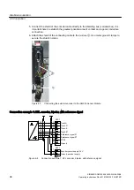


Always use the bipolar connection because its physical transmission properties are more
robust. Only if the encoder type employed does not output push-pull signals should you use the
unipolar connection.
6.5.8
Interconnecting optional connections
Depending on the range of options installed, further connections have to be interconnected.
Detailed information about interconnecting these options with the interfaces is provided in the
circuit manual.
6.5.9
Connecting the re-cooling unit to the drive
Connect the cable provided for the cooling unit to the corresponding interfaces on the drive and
the cooling unit. Further details are contained in the circuit diagram of the drive and the re-
cooling unit.
6.5.10
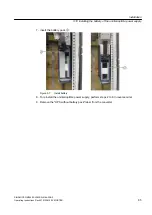
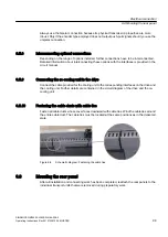
Fastening the cable ducts with cable ties
Fasten all cable ducts whose cover faces downward with cable ties. Wind the cable ties around
the entire cable duct. The cable ties must be located at the same positions as in the delivered
state.
Figure 6-9
Schematic diagram: Fastening the cable ties
6.6
Mounting the rear panel
After all installation and connecting work has been completed, reattach the rear panels to the
individual transport units that were removed during preparatory work.
Electrical connection
6.6 Mounting the rear panel
SINAMICS GM150 6SL3835-2LN44-2AA0
Operating Instructions Rev.201910281250 MUSTER
99
Summary of Contents for Sinamics GM150 6SL3835-2LN44-2AA0
Page 2: ...28 10 2019 12 50 V32 00 ...
Page 232: ...Index SINAMICS GM150 6SL3835 2LN44 2AA0 232 Operating Instructions Rev 201910281250 MUSTER ...
Page 233: ......
Page 236: ......
Page 238: ......


