


Connecting
3.4 Installing Control Unit
Inverter with CU240B-2 and CU240E-2 Control Units
Operating Instructions, 07/2010, FW 4.3.2, A5E02299792B AA
53
$9'&
$9'&
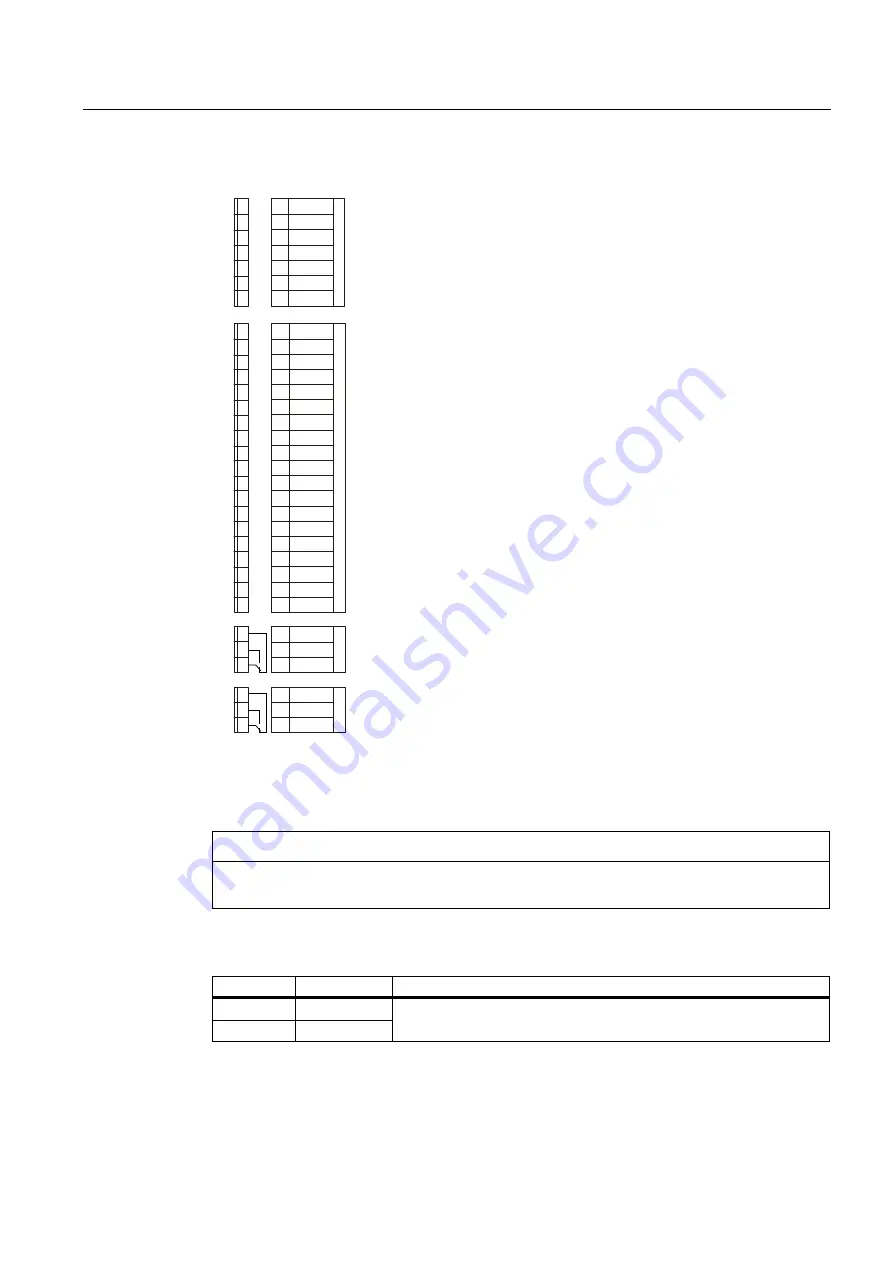
([SODQDWLRQV
7HUPLQDOV
7HUPLQDO
PDUNLQJV
99(OHFWURQLFVXSSO\LQSXWUHIHUUHGWR*1'
5HIHUHQFHSRWHQWLDOIRUWHUPLQDO
5HIHUHQFHSRWHQWLDOIRUGLJLWDOLQSXWV
$QDORJLQSXW99P$P$RUGLJLWDOLQSXW
5HIHUHQFHSRWHQWLDOIRUDQDORJLQSXW
$QDORJRXWSXW99P$P$PD[˖
RYHUDOOUHIHUHQFHSRWHQWLDO
9RXWSXWUHIHUUHGWR*1'PD[P$
RYHUDOOUHIHUHQFHSRWHQWLDO
$QDORJLQSXW99P$P$RUGLJLWDOLQSXW
5HIHUHQFHSRWHQWLDOIRUDQDORJLQSXW
$QDORJRXWSXW99P$P$PD[˖
RYHUDOOUHIHUHQFHSRWHQWLDO
'LJLWDORXWSXWSRVLWLYH$9'&
'LJLWDORXWSXWQHJDWLYH$9'&
0RWRUWHPSHUDWXUHVHQVRU37&.7<RUELPHWDO1&FRQWDFW
0RWRUWHPSHUDWXUHVHQVRU37&.7<RUELPHWDO1&FRQWDFW
9RXWSXWUHIHUHQFHSRWHQWLDO*1'PD[P$
RYHUDOOUHIHUHQFHSRWHQWLDO
5HIHUHQFHSRWHQWLDOIRUGLJLWDOLQSXWV
'LJLWDOLQSXW
'LJLWDOLQSXW
'LJLWDOLQSXW
'LJLWDOLQSXW
'LJLWDOLQSXW
'LJLWDOLQSXW
'LJLWDORXWSXWEUHDNFRQWDFW
'LJLWDORXWSXW12FRQWDFW
'LJLWDORXWSXWURRWFRQWDFW
'LJLWDORXWSXWEUHDNFRQWDFW
'LJLWDORXWSXW12FRQWDFW
'LJLWDORXWSXWURRWFRQWDFW
'21&
'212
'2&20
'21&
'212
'2&20
9287
*1'
$,
$,
$2
*1'
'2
'2
702725
702725
9287
*1'
',&20
',
',
',
',
',
',
9,1
*1',1
',&20
$,
$,
$2
*1'
Figure 3-13 Terminal strip on CU240E-2, CU240E-2 F, CU240E-2 DP and CU240E-2 DP-F
If you require more than six digital inputs, use analog inputs AI 0 or AI 1 as additional digital
inputs DI 11 or DI 12.
CAUTION
If your application requires UL certification, please observe the note regarding the digital
output in Section Technical data, CU240E-2 Control Unit (Page 262).
For a fail-safe digital input, use two "standard" digital inputs.
Terminals
Designation
Fail-safe digital input with Basic Safety
16
DI4
17
DI5
F-DI0