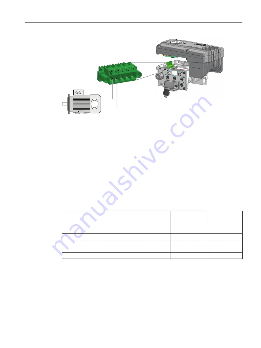
Siemens SINAMICS G110M Operating Instructions Manual Download Page 81

EMB+

EMB-

Figure 4-15

Simplied diagram of the motor holding brake connections

4.3.8

Connecting the PROFINET interface

Condition

The screen of the PROFINET cable must be connected with the protective earth. The solid copper 
core must not be scored when the insulation is removed from the core ends.

Description

Listed in the table below are the recommended Ethernet cables.

Table 4-7

Recommended Ethernet cables and cable length

Cable type

Max. length be‐
tween 2 convert‐
ers

Article Number

Industrial Ethernet FC TP Standard Cable GP 2 x 2 

100 m (328 ft)

6XV1840-2AH10

Industrial Ethernet FC TP Flexible Cable GP 2 x 2

85 m (278 ft)

6XV1870–2B

Industrial Ethernet FC Trailing Cable GP 2 x 2

85 m (278 ft)

6XV1870–2D

Industrial Ethernet FC Trailing Cable 2 x 2

85 m (278 ft) 

6XV1840–3AH10

Industrial Ethernet FC Marine Cable 2 x 2

85 m (278 ft)

6XV1840–4AH10

4.3.9

Terminal assignment dependent on interface configuration

The inputs and outputs of the frequency converter and the fieldbus interface have specific 
functions when set to the factory settings.

When you put the frequency converter into operation, you can change the function of each of 
its inputs and outputs and the setting of the fieldbus interface.

Installation

4.3 Electrical Installation

Distributed converter for SIMOGEAR geared motors
Operating Instructions, 10/2020, FW V4.7 SP13, A5E31298649B AL

79

Summary of Contents for SINAMICS G110M

Page 1: ...Operating Instructions Distributed converter for SIMOGEAR geared motors SINAMICS G110M 10 2020 Edition SINAMICS www siemens com drives ...

Page 2: ......

Page 3: ...ctions 10 2020 FW V4 7 SP13 A5E31298649B AL Changes in this manual Fundamental safety instructions 1 Introduction 2 Description 3 Installation 4 Commissioning 5 Uploading the converter settings 6 Protecting the converter settings 7 Advanced commissioning 8 Alarms faults and system messages 9 Corrective maintenance 10 Technical data 11 Appendix A ...

Page 4: ...those who based on their training and experience are capable of identifying risks and avoiding potential hazards when working with these products systems Proper use of Siemens products Note the following WARNING Siemens products may only be used for the applications described in the catalog and in the relevant technical documentation If products and components from other manufacturers are used the...

Page 5: ...327 Replacing the converter Uploading the converter settings Page 137 Replacing the Control Module Page 365 Downloading the converter settings Page 367 Replacing the Power Module Page 377 Acceptance of the safety functions The acceptance of the safety function Safe Torque Off is no longer described in the manual Instead we recommend that you use the corresponding wizard in the Startdrive Advanced ...

Page 6: ...Changes in this manual Distributed converter for SIMOGEAR geared motors 4 Operating Instructions 10 2020 FW V4 7 SP13 A5E31298649B AL ...

Page 7: ...tallation 46 4 2 4 Grounding the terminal housing 55 4 2 5 Installing the 24V power supply 55 4 3 Electrical Installation 60 4 3 1 SINAMICS G110M Electrical data 60 4 3 2 EMC installation guidelines 62 4 3 2 1 Connections and interference suppression 62 4 3 2 2 Basic EMC rules 62 4 3 2 3 Equipotential bonding 63 4 3 3 Protective conductor 65 4 3 4 Connection and cables 67 4 3 5 Connecting the moto...

Page 8: ...sioning with the IOP 2 113 5 4 4 p0015 Default settings 116 5 4 5 Quick commissioning with a PC 122 5 4 5 1 Creating a project 123 5 4 5 2 Transfer converters connected via USB into the project 124 5 4 5 3 Go online and start the commissioning Wizard 125 5 4 5 4 Selecting the control mode 127 5 4 5 5 Identify motor data 128 5 5 Restoring the factory settings 130 5 5 1 Saving motor data for non sta...

Page 9: ...wo wire control clockwise counterclockwise rotation 2 176 8 5 4 Three wire control enable clockwise counterclockwise rotation 178 8 5 5 Three wire control enable ON reverse 180 8 6 Drive control via PROFIBUS or PROFINET 182 8 6 1 Receive data and send data 182 8 6 2 Telegrams 183 8 6 3 Control and status word 1 188 8 6 4 Control and status word 3 190 8 6 5 NAMUR message word 193 8 6 6 Parameter ch...

Page 10: ...nce test 256 8 16 Setpoints 258 8 16 1 Overview 258 8 16 2 Analog input as setpoint source 260 8 16 3 Specifying the setpoint via the fieldbus 261 8 16 4 Electromechanical potentiometer 262 8 16 5 Motorized potentiometer as setpoint source 263 8 16 6 Fixed speed setpoint as setpoint source 265 8 17 Setpoint calculation 269 8 17 1 Overview 269 8 17 2 Invert setpoint 270 8 17 3 Inhibit direction of ...

Page 11: ...stem messages 345 9 1 Status LED overview 345 9 2 Operating states indicated via LEDs 346 9 3 System runtime 349 9 4 Identification maintenance data I M 350 9 5 Alarms alarm buffer and alarm history 351 9 6 Faults alarm buffer and alarm history 354 9 7 List of alarms and faults 357 10 Corrective maintenance 363 10 1 Replacing the Control Module 365 10 2 Downloading the converter settings 367 10 2 ...

Page 12: ...n 395 11 7 Protecting persons from electromagnetic fields 396 A Appendix 397 A 1 New and extended functions 397 A 1 1 Firmware version 4 7 SP13 397 A 1 2 Firmware version 4 7 SP10 398 A 1 3 Firmware version 4 7 SP9 400 A 1 4 Firmware version 4 7 SP6 402 A 1 5 Firmware version 4 7 SP3 403 A 1 6 Firmware version 4 7 405 A 1 7 Firmware version 4 6 SP6 406 A 1 8 Firmware version 4 6 407 A 2 Interconne...

Page 13: ...s energy sources e g compressed air hydraulic systems or water Switch the energy sources to a safe state 8 Check that the correct drive system is completely locked After you have completed the work restore the operational readiness in the inverse sequence WARNING Risk of electric shock and fire from supply networks with an excessively high impedance Excessively low short circuit currents can lead ...

Page 14: ...suitable power supply exposed components may carry a hazardous voltage Contact with hazardous voltage can result in severe injury or death Only use power supplies that provide SELV Safety Extra Low Voltage or PELV Protective Extra Low Voltage output voltages for all connections and terminals of the electronics modules WARNING Electric shock due to damaged motors or devices Improper handling of mot...

Page 15: ...ls or fastening methods can damage the screws of the equipment Be sure to only use screwdrivers which exactly match the heads of the screws Tighten the screws with the torque specified in the technical documentation Use a torque wrench or a mechanical precision nut runner with a dynamic torque sensor and speed limitation system WARNING Active implant malfunctions due to electromagnetic fields Conv...

Page 16: ...for operation with grounded line conductors you must perform the following measures IT system Use a ground fault monitor and eliminate the fault as quickly as possible TN or TT systems with grounded line conductor Use an isolating transformer on the line side WARNING Fire due to inadequate ventilation clearances Inadequate ventilation clearances can cause overheating of components with subsequent ...

Page 17: ...ts Ensure that the safety functions used in your drives and automation tasks are adjusted and activated through appropriate parameterizing Perform a function test Only put your plant into live operation once you have guaranteed that the functions relevant to safety are running correctly Note Important safety notices for Safety Integrated functions If you want to use Safety Integrated functions you...

Page 18: ...e case of a fault the motor can overheat resulting in fire and smoke This can result in severe injury or death Further excessively high temperatures destroy motor components and result in increased failures as well as shorter service lives of motors Operate the motor according to the relevant specifications Only operate the motors in conjunction with effective temperature monitoring Immediately sw...

Page 19: ...c components modules or devices in their original packaging or in other suitable materials e g conductive foam rubber of aluminum foil Only touch components modules and devices when you are grounded by one of the following methods Wearing an ESD wrist strap Wearing ESD shoes or ESD grounding straps in ESD areas with conductive flooring Only place electronic components modules or devices on conduct...

Page 20: ...to provide support for typical tasks As the user you yourself are responsible for ensuring that the products described are operated correctly Application examples do not relieve you of your responsibility for safe handling when using installing operating and maintaining the equipment Fundamental safety instructions 1 3 Warranty and liability for application examples Distributed converter for SIMOG...

Page 21: ...duct versions are used Use of product versions that are no longer supported and failure to apply the latest updates may increase customer s exposure to cyber threats To stay informed about product updates subscribe to the Siemens Industrial Security RSS Feed under https www siemens com industrialsecurity https new siemens com global en products services cert html Subscriptions Further information ...

Page 22: ...nside and outside the components under fault conditions caused by for example Component failure Software errors Operation and or environmental conditions outside the specification External influences damage 3 Hazardous shock voltages caused by for example Component failure Influence during electrostatic charging Induction of voltages in moving motors Operation and or environmental conditions outsi...

Page 23: ...such a way that it is sufficient for all standard applications and enables drives to be commissioned as efficiently as possible Where it appears useful additional information for entry level personnel has been added The operating instructions also contain information about special applications Since it is assumed that readers already have a sound technical knowledge of how to configure and paramet...

Page 24: ...Introduction 2 1 About the Manual Distributed converter for SIMOGEAR geared motors 22 Operating Instructions 10 2020 FW V4 7 SP13 A5E31298649B AL ...

Page 25: ...ment contains recommendations relating to third party products Siemens accepts the fundamental suitability of these third party products You can use equivalent products from other manufacturers Siemens does not accept any warranty for the properties of third party products Use of OpenSSL This product contains software developed in the OpenSSL project for use within the OpenSSL toolkit This product...

Page 26: ...t 3AC 0 Input V In 26A SINA MICS Pow er Mod ule 230 Input 3AC 380 480V 31 5A 50 60 Hz Moto r IEC 7 5kW 11kW LO NEM A 10hp 15hp LO Prote ction IP55 Weig ht 7 0Kg Temp Rang e 0 50 C Seria l No XAT8 12 00 1298 MLFB 6SL3 224 0BE2 7 5U A0 Axx Outp ut 3AC 0 Input V In 26A SIN AM ICS Po we r Mo dul e 230 Inp ut 3AC 380 480 V 31 5A 50 60H z Mo tor IEC 7 5 kW 11 kW LO NE MA 10h p 15 hp LO Pro tec tion IP5 ...

Page 27: ... in the CM and the PM Three phase motor The SINAMICS G110M is designed for mounting on the SIMOGEAR geered motors It is compatible with motors of frame sizes 71 to 112 The Power Modules are designed for a specific power range and the Terminal Housings are designed to work with specific motors The Terminal Housing not only allows the direct mounting onto a motor but specific cable glands and mains ...

Page 28: ...ands 6SL3544 0MB02 1FA0 PROFINET FS100 112 Cable glands 6SL3544 0NB02 1FA0 PROFINET FS71 HanQ 4 2 7 8 6SL3544 0TB02 1FA0 PROFINET FS80 90 HanQ 4 2 7 8 6SL3544 0PB02 1FA0 PROFINET FS100 112 HanQ 4 2 7 8 6SL3544 0QB02 1FA0 AS i FS71 Cable glands 6SL3544 0LB02 1MA0 AS i FS80 90 Cable glands 6SL3544 0MB02 1MA0 AS i FS100 112 Cable glands 6SL3544 0NB02 1MA0 AS i FS71 HanQ 4 2 7 8 6SL3544 0TB02 1MA0 AS ...

Page 29: ... M12 plastic gland used for the EM brake cable entry 6SL3566 2VA00 0GA0 HanQ connector kit Comprises the following connectors Connector cap 7 8th internal thread used for the 24 V power blanking cap HanQ blanking cap used for the mains input blankingcap M12 plastic gland used for the EM brake cable entry 6SL3566 2LA00 0GA0 Repair Switch The Repair Switch allows the motor converter to be isolated f...

Page 30: ...ors in combination with the SINAMICS G110M see the MD50 1 catalog SIMOGEAR geared motors and DT configurator Description 3 2 SINAMICS G110M converter Distributed converter for SIMOGEAR geared motors 28 Operating Instructions 10 2020 FW V4 7 SP13 A5E31298649B AL ...

Page 31: ...he figure and table below The layout and interfaces of the AS i variant is shown in a separate figure and table below The connections on the terminal housing are delivered with either HAN Q pluggable or Glanded connectors depending on the variant that has been ordered Description 3 3 General layout SINAMICS G110M system Distributed converter for SIMOGEAR geared motors Operating Instructions 10 202...

Page 32: ...GXOH WRS YLHZ 3RZHU 0RGXOH LQWHUQDO YLHZ 7HUPLQDO KRXVLQJ ZLWK RQWURO 0RGXOH 866 352 86 1HWZRUN 7HUPLQDWLRQ 6ZLWFK Figure 3 2 General layout of the system all variants except CU240M AS i Description 3 3 General layout SINAMICS G110M system Distributed converter for SIMOGEAR geared motors 30 Operating Instructions 10 2020 FW V4 7 SP13 A5E31298649B AL ...

Page 33: ...ital output 0 and digital output 1 18 Memory card reader 7 Analog input 0 and analog input 1 19 Braking resistor motor connection terminals 8 External 24 Vdc OUT 20 Communications Power Interface CPI interface ribbon cable 9 External 24 Vdc IN 21 PROFIBUS USS address and commissioning DIP switches 1 and 2 10 Digital input 0 and digital input 1 22 EM Brake mains supply connection terminals 11 Mains...

Page 34: ...13 14 8 9 10 11 Figure 3 3 SINAMICS G110M ASi General Layout Description 3 3 General layout SINAMICS G110M system Distributed converter for SIMOGEAR geared motors 32 Operating Instructions 10 2020 FW V4 7 SP13 A5E31298649B AL ...

Page 35: ... and 1 15 EM brake mains supply connection terminals 8 Digital inputs 2 and 3 16 Communications cable Protection against unauthorized access via the USB interface WARNING Unsafe operating states resulting from manipulation of the converter software Manipulation of the converter software can cause unsafe operating states in your system that may lead to death serious injury and property damage Secur...

Page 36: ...hazardous substances in electrical and electronic devices RoHS European EMC Directive The compliance of the converter with the regulations of the Directive 2014 30 EU has been verified through full compliance with IEC EN 61800 3 Underwriters Laboratories North American market Converters provided with one of the test symbols displayed fulfill the requirements stipulated for the North American marke...

Page 37: ...nt directives prototype test certificates manufacturers declarations and test certificates for functions relating to functional safety Safety Integrated http support automation siemens com WW view en 22339653 134200 Certificates for products that were certified by UL http database ul com cgi bin XYV template LISEXT 1FRAME index html Certificates for products that were certified by TÜV SÜD https ww...

Page 38: ...Description 3 4 Directives and standards Distributed converter for SIMOGEAR geared motors 36 Operating Instructions 10 2020 FW V4 7 SP13 A5E31298649B AL ...

Page 39: ...The converter can cause a direct current on the PE conductor If the wrong type of protection device is used then the expected protection by such a device could fail to provide the expected protection If a residual current device RCD is used to provide protection in case of direct or indirect contact only a type B RCD may be used on the power supply side of the converter CAUTION Burns due to high t...

Page 40: ...able 4 1 Converter dimensions Frame size H mm L mm D1 mm D2 mm D3 mm W mm without glands A 135 270 208 216 161 132 B 135 309 208 216 181 132 Clearance distance The G110M system requires a minimum clearance distance around and above the converter of 150 mm PP PP PP PP PP PP PP Figure 4 2 G110M Clearance distances Installation 4 1 Mechanical Installation Distributed converter for SIMOGEAR geared mot...

Page 41: ... and indicated by the ground symbol These fixing points provide the correct earthing between the Terminal Housing and the motor and MUST be used All fixing bolts for the Terminal Housing are supplied with each Terminal Housing Note FS 80 90 Terminal Housing 21 mm fixing screws The 21 mm fixing screws for the FS 80 90 Terminal Housing are not supplied with the product 6 PP PP PP PP PP 6 6 Figure 4 ...

Page 42: ...egion WW language en nodeid 10028832 tree CatalogTree regionUrl 2F autoopen false activetab product topAnch activetab config The Configurator tool allows the user to precisely configure a motor with all the accessories and options that are required then generate dimensional data including 2D and 3D CAD models which can be downloaded to the users local system The figure below shows an example of th...

Page 43: ...orientation The G110M system has been designed to operate in any orientation depending on the motor mounting configuration Installation 4 1 Mechanical Installation Distributed converter for SIMOGEAR geared motors Operating Instructions 10 2020 FW V4 7 SP13 A5E31298649B AL 41 ...

Page 44: ...ctions should be performed DANGER Electrical shock due to unexpected voltages When the converter and motor are powered up high voltages are present in the electrical components of the system any contact with these components could result in severe personal injury or death Don t apply the mains supply and external power sources to the system during the installation procedure NOTICE Overheating the ...

Page 45: ...NOTICE Converter must not be used as a step or ledge The converter has not been designed to support a substantial weight Should substantial weight be placed on the converter it could result in severe damage to the equipment Don t use the converter as a step or a ledge Note Diagrams and illustrations In some of the diagrams and illustrations throughout this section the colour of components or cable...

Page 46: ...g should be made as this would permanently damage the seal and significantly reduce the IP rating of the Terminal Housing 2 Remove the blanking plate 1 Unscrew the four screws holding the blanking plate in place on the Terminal Housing 2 Do not try and remove the seal on the Terminal Housing Note The seal on the Terminal Housing behind the blanking plate is a moulded seal and no attempt to remove ...

Page 47: ...ot be fitted on the same side as the CPI 5 Remove the Terminal Housing terminal connectors 1 Remove the mains terminals connector 2 Remove the motor terminals connector Notes The terminal connectors are removed to allow easy access to the earthing posts located underneath the individual termi nals There are no screws holding down the connectors they are secured and held in place when the Control M...

Page 48: ... the correct direction to allow connection to the earthing post on the Terminal Housing Note The earthing cable is supplied with the Terminal Housing On the FS80 90 Terminal Housings there are two additional fixing points which are the earthing points between the Ter minal Housing and the motor These earthing points must be used and therefore the earthing cable does not need to be fitted If the SI...

Page 49: ...hing points must be used and therefore the earthing cable does not need to be fitted The FS80 90 Terminal Housings cannot be fitted directly over the terminal block of the motor the terminal block of the motor must be removed from the motor then the Terminal Housing is fitted to the motor and then the motor terminal block is fitted back onto the motor Exact dimensions and fixing points of the Term...

Page 50: ... the external EM brake cable through the EM brake cable gland 2 Connect the external EM brake cable to the EM brake termi nal block 3 Ensure that the plastic insulation sleeve is fitted correctly to the EM brake terminal block which is part of the accessories supplied with the product 4 Tighten the cable gland to secure the cable in place Notes Only a 180 Vdc EM brake can be used If a brake is not...

Page 51: ...l be done after the CPI is fitted as shown later in this procedure 8 Connecting the mains earth cable HANQ variant 1 Connect the HANQ earth connection to the earthing post of the Terminal Housing 2 Tighten the earthing post screw to 1 5 Nm Note If the SINAMICS G110M is ordered as a complete system then all mechanical and electrical installation is completed in the factory prior to delivery 9 Conne...

Page 52: ...Connect the L1 connection from the input HANQ connector to the output HANQ connector 3 Connect the L2 connection from the input HANQ connector to the output HANQ connector 4 Connect the L3 connection from the input HANQ connector to the output HANQ connector Note The power through cables are provided with the Terminal Hous ing and are the correct size and dimensions to allow the power through conn...

Page 53: ...tput cable through the cable gland Note On the glanded variant no pre cut cables are provided 12 Fitting the internal braking resistor The internal braking resistor is an optional extra and is fitted into the Terminal Housing 1 Slide the internal braking resistor into place on the opposite side to which the CPI will be fitted 2 Fit the internal braking resistor securing bracket 3 Secure the bracke...

Page 54: ...ating of the Terminal Housing Notes Screws tightening torque 1 5 Nm The Communications and Power Interface CPI can be fitted on the left or right side of the Terminal Housing but must always be fitted on the opposite side of the Terminal Housing from the internal braking resistor 16 Final connection and adjustments 1 Connect the temperature sensor connector into the connec tor at the top edge of t...

Page 55: ...nation switch When using the PROFIBUS or USS communications protocols the last converter on the network must have the network termi nation switch in the ON position 2 21 19 Fit memory card into the Power Module To allow parameter settings to be stored or copied to the con verter the memory card must be fitted into the memory card reader Installation 4 2 System Installation Distributed converter fo...

Page 56: ...iameter of 20 mm Wiring dimensions 0 25 2 5 mm2 without isolated cable ends ferrels 0 25 1 5 mm2 with isolated cable ends ferrels Note Unswitched and switched power supply The unswitched 24 V power supply also known as non switched on X1 2 and X1 4 provides power to the general electronics of the Control Unit The switched 24 V power supply on X1 1 and X1 5 supplies power for the two digital output...

Page 57: ...LQ Figure 4 5 Terminal Housing PE terminal 4 2 5 Installing the 24V power supply Overview The optional 24 V PSU allows the user to draw the necessary 24 V to power the internal electronics of the Control Module direct from the converters DC link voltage This has the advantage that no external cabling is required and therefore only a 3 phase mains supply cable is required The following electronics ...

Page 58: ... installing the 24 V PSU If an external braking resistor is not used the cable gland opening must be sealed with a blanking plug to maintain the IP rating of the system The 24 V DC IN and OUT connectors and the CPI must be sealed with screw caps to maintain the IP rating of the system When using the 24 V PSU there is no longer any isolation between the 24 V PSU and the digital outputs of the syste...

Page 59: ...U to the side of the terminal housing ensuring that no cables or wiring are trapped between the 24 V PSU and the terminal housing Tightening torque 1 5 Nm 6 Connect the input cable to the DC link terminals in the terminal housing black to DC and red to DC 7 The 4 way 24 V cable is routed underneath and then over the top of the CM 8 Fit the 4 way connector as shown in the illustration below 9 Fit t...

Page 60: ... outputs The Fan used with the Wall Mount Kit only The external 24 V power supply can be used in place of the black auxiliary cable you cannot use both at the same time but the G110M AS i must always use the yellow cable as the G110M AS i cannot be used as a stand alone converter Note Loss of power to the 24 V external supply If the mains supply to the converter is removed then the external 24 V s...

Page 61: ...Figure 4 8 AS i Cables with M12 connector Installation 4 2 System Installation Distributed converter for SIMOGEAR geared motors Operating Instructions 10 2020 FW V4 7 SP13 A5E31298649B AL 59 ...

Page 62: ...at the converter is powered up but the motor is not running The phenomenon of capacitive reactive current standby occurs in all converters with filter capacitors on the line side In applications where a number of converters are connected to one line supply and where only a small proportion of the converters will be running at any one time the standby currents in the non running converters must be ...

Page 63: ... maximum combined currents for all the digital outputs is 500 mA Note Line impedance To ensure trouble free operation we recommend the line impedance is less than 1 RSC 100 Note UL transient surge suppression requirements To ensure that the electrical installation of this equipment complies with the UL requirements for transient surge protection the following requirement must be adhered to Transie...

Page 64: ...C rules Measures to limit Electromagnetic Interference EMI In the following list are the necessary measures that must be taken to ensure the correct installation of the Converter within a system which should minimize the effects of EMI Cables Keep all cable lengths to the minimum possible length avoid excessive cable lengths Route always signal and data cables as well as their associated equipoten...

Page 65: ...connector housings for shielded data cables for example PROFIBUS cables 4 3 2 3 Equipotential bonding Equipotential bonding within the drive system has to be established by connecting all electrical and mechanical drive components transformer motor and driven machine to the grounding system These connections are established by means of standard heavy power PE cables which do not need to have any s...

Page 66: ...components They are made with standard heavy power PE conductors without special high frequency properties and ensure low frequency equipotential bonding as well as protection against injury The line supply cable of the converter can be unshielded The converter has to be grounded by this cable The converter enclosure provides high frequency equipotential bonding between the converter and the motor...

Page 67: ...DEOH ULYHQ PDFKLQH 3 Figure 4 10 Additional high frequency bonding of the drive system 4 3 3 Protective conductor WARNING Danger to life caused by high leakage currents for an interrupted protective conductor The drive components conduct a high leakage current via the protective conductor Touching conductive parts when the protective conductor is interrupted can result in death or serious injury D...

Page 68: ...nts placed on the protective conductor For permanent connection the protective conductor must fulfill at least one of the following conditions The protective conductor is routed so that it is protected against damage along its complete length Cables routed inside electrical cabinets or enclosed machine housings are considered to be adequately protected against mechanical damage As a conductor of a...

Page 69: ...d 15 m 49 ft Digital outputs Unscreened 15 m 49 ft Analog input Screened 15 m 49 ft Motor cable with Wall Mount Kit 5 m 16 40 ft The maximum cable lengths for communications are determined by a number of factors for example the maximum length of the cable for USS and PROFIBUS are dependent on the data transfer rate being utilized by the network In some cases it is possible to extend the cable leng...

Page 70: ... The extender allows the distance between the AS i master and an AS i segment of the network to be extended to a maximum of 100 m 328 ft With repeaters connected in parallel a cable length significantly longer than 300 m 984 ft can be achieved The maximum span is 500 m 1640 ft The only limitation of the extender is that slaves can only be used downstream from the extender Extension plug Using the ...

Page 71: ...RUW 352 86 866 287 352 1 7 3RUW RJLFDO VXSSO 1 VZLWFKHG 9 RJLFDO VXSSO 287 VZLWFKHG 9 RJLFDO VXSSO 287 XQVZLWFKHG 9 RJLFDO VXSSO 1 XQVZLWFKHG 9 14 9DULDQW ODQGHG 9DULDQW 9 9 9 2 2 9 9 9 9 9 2 2 9 9 Figure 4 11 Outline block diagram SINAMICS CU240M and PM240M Installation 4 3 Electrical Installation Distributed converter for SIMOGEAR geared motors Operating Instructions 10 2020 FW V4 7 SP13 A5E3129...

Page 72: ... the SINAMICS G110M are listed in the following documents and can be accessed using the relevant links SINAMICS and motors for Single Axis Drives D31 catalog https w3app siemens com mcms infocenter content en Pages order_form aspx nodeKey key_566000 infotype catalogs linkit null Siemens supplementary product information http support automation siemens com WW view en 65355810 Installation 4 3 Elect...

Page 73: ...les and connectors that the connections match those given in the connection diagrams For example the orientation of the key notch on the CPI connector may not match the key notch on the mating cable connector being constructed in this instance the pin numbers on the connector being made needs to be ignored to allow the correct orientation and wiring of the connector to ensure a proper match to the...

Page 74: ... 6 L 8 XQFWLRQDO DUWK 6 L RQQHFWLRQ X03 M12 connector 5 Pole female 24V Power supply USS PROFIBUS PROFINET The unswitched 24 V power supply 1L is required for the device to function Use a power supply with PELV Protective Extra Low Voltage For applications in USA and Canada Use a power supply NEC Class 2 The 0 V of the power supply must be connected with low resistance to the PE of the system The ...

Page 75: ... 9 0 LJLWDO 2XWSXW XQFWLRQDO DUWK 9 P PD X05 2 5 4 1 3 M12 connector 5 Pole female Specification PNP SIMATIC compatible low 5 V high 10 V maximum input voltage 30 V The Control Module CM is fit ted inside the terminal housing and is connected by ribbon ca ble to the CPI 8QVZLWFKHG 9 LJLWDO QSXW 8QVZLWFKHG 9 0 LJLWDO QSXW XQFWLRQDO DUWK 9 X07 2 5 4 1 3 8QVZLWFKHG 9 LJLWDO QSXW 8QVZLWFKHG 9 0 LJLWDO...

Page 76: ... on the G110M system are located inside the Control Unit and motor housing The connections are shown in the following figure 5 5 8 9 0 0 Figure 4 13 Control Unit motor and power connections 4 3 5 Connecting the motor to the converter in a star or delta connection Overview Standard induction motors up to a rated power of approximately 3 kW are usually connected in star delta connection Y Δ at 400 V...

Page 77: ...s As a consequence the motor power is increased by a factor 3 1 73 In the range f 0 87 Hz the motor can output its rated torque MN The maximum voltage U 400 V is avail able at a frequency of f 3 50 Hz 87 Hz The motor only goes into field weakening above 87 Hz The higher motor power when operated with an 87 Hz characteristic has the following disadvantages The converter must supply approximately 1 ...

Page 78: ...order_form aspx nodeKey key_566000 infotype catalogs linkit null Installation using power through daisy chain The converter has been designed to allow a converter to utilize power through to provide the mains power for a number of converters in a daisy chain The maximum current limits for the daisy chain are given below For the HanQ variants the maximum current of the daisy chained converters must...

Page 79: ...motor circuit at the output side In case of insulation failure in the motor circuit the overcurrent trip of the converter meets the requirements of IEC 60364 4 41 2005 AMD1 2017 Section 411 and Annex D for protection against electric shock Observe the installation specifications for this converter Ensure the continuity of the protective conductor Observe the applicable installation standards Insta...

Page 80: ...lation failure ground fault fault to frame then you must use additional residual current protective devices RCD type B In order that an RCD does not unnecessarily trip as a result of operational leakage currents the following preconditions must be fulfilled The neutral point of the line supply is grounded Use a Siemens SIQUENCE RCCB series 5SV364 4 type B short time delayed K with a rated residual...

Page 81: ...thernet FC TP Flexible Cable GP 2 x 2 85 m 278 ft 6XV1870 2B Industrial Ethernet FC Trailing Cable GP 2 x 2 85 m 278 ft 6XV1870 2D Industrial Ethernet FC Trailing Cable 2 x 2 85 m 278 ft 6XV1840 3AH10 Industrial Ethernet FC Marine Cable 2 x 2 85 m 278 ft 6XV1840 4AH10 4 3 9 Terminal assignment dependent on interface configuration The inputs and outputs of the frequency converter and the fieldbus i...

Page 82: ...assignment 4 3 10 Wiring example for the factory settings To ensure that the factory setting of the interfaces can be used you must wire your drive as shown in the following examples Factory pre assignment of the interfaces on the drive For a complete technical specification of the individual connections please refer to following section of this manual Connection and cables Page 67 FNQRZOHGJH IDXO...

Page 83: ...ith fixed setpoints default ASi Note Unswitched and switched power supply The unswitched 24 V power supply also known as non switched on X1 2 and X1 4 provides power to the general electronics of the Control Unit The switched 24 V power supply on X1 1 and X1 5 supplies power for the two digital outputs DI0 and DI1 For a complete explanation of the unswitched and switched 24 V supplies and their li...

Page 84: ...EXV LV QRW DFWLYH RQWURO YLD 352 GULYH 7HOHJUDPP 1R XQFWLRQ 1R XQFWLRQ FNQRZOHGJH IDXOW ODUP DXOW 2 2 Figure 4 19 Default settings 7 Switch over between fieldbus and jogging using DI 3 default DP PN 0RWRU SRWHQWLRPHWHU GHFUHDVH 21 2 0RWRU SRWHQWLRPHWHU LQFUHDVHG FNQRZOHGJH IDXOW ODUP DXOW 2 2 Figure 4 20 Default settings 9 Motorized potentiometer MOP 6SHHG VHWSRLQW 21 2 5HYHUVH FNQRZOHGJH IDXOWV O...

Page 85: ...JH IDXOW ODUP DXOW 2 2 Figure 4 23 Default settings 18 Two wire control with method 3 21 OHIW QDEOH 2 21 ULJKW 6SHHG VHWSRLQW FNQRZOHGJH IDXOW ODUP DXOW 2 2 Figure 4 24 Default settings 19 Three wire control with method 1 Installation 4 3 Electrical Installation Distributed converter for SIMOGEAR geared motors Operating Instructions 10 2020 FW V4 7 SP13 A5E31298649B AL 83 ...

Page 86: ...W 2 2 Figure 4 26 Default settings 21 Fieldbus USS FNQRZOHGJH IDXOW 21 2 5HYHUVH ODUP DXOW L HG VSHHG VHWSRLQW VHOHFWLRQ LW L HG VSHHG VHWSRLQW VHOHFWLRQ LW 2 2 Figure 4 27 Default settings 28 Conveyor with 2 fixed setpoints Installation 4 3 Electrical Installation Distributed converter for SIMOGEAR geared motors 84 Operating Instructions 10 2020 FW V4 7 SP13 A5E31298649B AL ...

Page 87: ...D 6 L 6LQJOH 6ODYH 5HDG YLD 3 21 L HG 6SHHG VHWSRLQW 2 2 RU DFNQRZ OHGJH IDXOW 0RWRU LV UXQQLQJ DXOW RU DUQLQJ FRGH 5HTXHVW DXOW DQG ODUP FRGH 7UDQVPLW DWD 5HFHLYH DWD 6 L 6 L 6 L 2 6 L 2 6 L 3 6 L 6 L 6 L 35 6 L 35 Figure 4 29 Default settings 30 ASi Single slave with fixed setpoints default ASi Installation 4 3 Electrical Installation Distributed converter for SIMOGEAR geared motors Operating In...

Page 88: ... 35 6 L 35 Figure 4 30 Default settings 31 ASi Dual slave with fixed setpoints RQWURO YLD 6 L 6LQJOH 6ODYH 5HDG 21 2 OHIW 21 2 ULJKW 6ZLWFK RYHU VRXUFH RI VSHHG VHWSRLQW 2SHUDWLRQ HQDEOH RU DFNQRZOHGJH IDXOW 6SHHG VHWSRLQW VFDOLQJ 0DVWHU FRQWURO DFWLYH DXOW RU DUQLQJ FRGH 6SHHG VHWSRLQW 6HWSRLQW IURP WKH 3RWHQWLRPHWHU 7UDQVPLW GDWD 5HFHLYH GDWD 6 L 2 6 L 2 6 L 2 6 L 2 6 L 2 6 L 2 6 L 3 6 L 3 6 L 6...

Page 89: ...LYH DWD 6ODYH 7UDQVPLW FXUUHQW DQG DFWXDO VSHHG DXOW RU DUQLQJ FRGH 5HTXHVW DXOW DQG ODUP FRGH FOLF WUDQVPLVVLRQ RI VSHHG VHWSRLQW RU DF OLF 77 DWD 6HOHFW 6ODYH RU 6ODYH 6HOHFW 6ODYH RU 6ODYH 6 L 6 L 6 L 6 L 6 L 6 L 6 L 6 L 6 L 2 6 L 2 6 L 2 6 L 2 6 L 2 6 L 2 6 L 2 6 L 2 6 L 3 6 L 35 6 L 35 Figure 4 33 Default settings 34 ASi Dual slave with setpoint Installation 4 3 Electrical Installation Distri...

Page 90: ...rated Function Manual Further information on fieldbus profiles and interfaces can be found in the Fieldbus Function Manual For a list of all the manuals associate with this product see Manuals for your converter Page 415 4 4 2 PROFINET You can either integrate the converter in a PROFINET network or communicate with the converter via Ethernet The converter in PROFINET IO operation 3 6XSHUYLVRU 352 ...

Page 91: ...card or from the programming device Shared Device for converters that support PROFIsafe The converter as Ethernet node 3 6 1 0 6 6 1 0 6 0 6 1 0 6 6 1 0 6 6 1 0 6 WKHUQHW Figure 4 35 The converter as Ethernet node examples Further information on the operation as Ethernet nodes can be found in the Function Manual Fieldbuses Manuals for your converter Page 415 Further information on PROFINET Further...

Page 92: ...P address PROFINET also uses the device name to identify PROFINET devices Device name The device name must be unique across the PROFINET network To assign the device name you need an engineering software e g HW Config The converter saves the device name on the inserted memory card IP address In addition to the device name PROFINET also uses an IP address You have the following options to specify t...

Page 93: ...MENS SINAMICS DATA CFG on the memory card 2 Unzip the GSDML file on your computer 3 Import the GSDML into the engineering system of the controller You have now installed the GSDML in the engineering system of the controller 4 4 3 PROFIBUS 4 4 3 1 Integrating the converter in PROFIBUS Procedure 1 Integrate the converter in the bus system e g line topology of the control using PROFIBUS cables and th...

Page 94: ...120D with S7 300 400F via PROFINET or PROFIBUS with Safety Integrated via terminal and HMI https support industry siemens com cs ww en view 60441457 Controlling the speed of a SINAMICS G110M G120 Startdrive with S7 1500 TO via PROFINET or PROFIBUS with Safety Integrated via terminal and HMI https support industry siemens com cs ww en view 78788716 4 4 3 3 Installing the GSD Procedure 1 Save the GS...

Page 95: ... p0918 126 It is only possible to change p0918 if an invalid address is set in the address switch General layout SINAMICS G110M system Page 29 Setting the bus address Procedure 1 Set the address using one of the subsequently listed options Via the address switch With a commissioning tool via p0918 2 Switch off the converter power supply 3 Wait until all LEDs on the converter are dark 4 Switch on t...

Page 96: ...gure the communication of the converter via AS i the following options are available for commissioning the converter Using parameter p0015 select which default setting you wish to accept Table 4 8 p0015 macro drive unit p001 5 Designation Meaning 30 Default setting 30 single slave mode standard addressing Single slave mode where the control system specifies a fixed frequency 31 Default setting 31 ...

Page 97: ...e AS i network p2013 0 Single Slave factory setting p2013 2 Dual Slave If for the commissioning you select the default setting 30 or 32 Single Slave or 31 or 34 Dual Slave p2013 is assigned the appropriate value Note Changes made to p2012 and p2013 Changes made to the p2012 and p2013 parameters take effect immediately after the change If you work with Startdrive you must back up the changes so the...

Page 98: ...sing via the addressing device is made offline Further information is contained in the AS Interface system manual Section Setting the AS i address AS i System Interface Manual https support industry siemens com cs gb en view 1171856 Addressing via parameters The address assignment is made with the p2012 0 and p2012 1 parameters If you assign the address via Startdrive you must back up the settings...

Page 99: ...rn the dial on the Programmer to the ADDR position The display will indicate that this mode has been selected 3 Press the button the screen will display the text SEt 0 with a small flashing 0 to the left of the display 4 Press the button until you reach the required number By pressing both the and simultaneously you can toggle between A and B identifiers of the address 5 Press the button to confir...

Page 100: ... address of the other slave To change an existing address of a slave the following procedure should be performed 1 Plug the AS i Programmer into the addressing socket of the converter 2 Turn the dial on the Programmer to the ADDR position The display will indicate that this mode has been selected 3 Press the button the screen will display uSE and the number of the lower addressed slave The existin...

Page 101: ...rface in the converter Page 162 6 If necessary set further func tions in the converter Page 155 7 Save your settings Page 137 5IF DPOWFSUFS JT JOTUBMMFE PNNJTTJPOJOH JT DPNQMFUFE 1SFQBSF GPS DPNNJTTJPOJOH 1FSGPSN RVJDL DPNNJTTJPOJOH BDUPSZ TFUUJOH TV DJFOU POWFS UFS XJUI GBDUPSZ TFUUJOHT VSUIFS DPOWFSUFS GVODUJPOT P FT EWBODFE DPNNJTTJP OJOH 6QMPBEJOH TFUUJOHT SFRVJSFE OPU VTFE JFMECVT DPOOFDUJPO ...

Page 102: ... with CU240M 3RK1922 2BP00 STARTER 1 Commissioning tool PC software DVD 6SL3072 0AA00 0AG0 Startdrive 2 Commissioning tool PC software DVD 6SL3072 4CA02 1XG0 PC Connection Kit Contains the 3 m USB cable necessary to con nect your converter to a PC 6SL3255 0AA00 2CA0 1 Internet STARTER download http support automation siemens com WW view en 26233208 2 Internet StartDrive download http support autom...

Page 103: ... if required 5 Article No 6 Model Type Size 7 Mounting position 8 Degree of protection according to IEC 60034 5 or IEC 60529 9 Weight m kg 10 Customer ID 11 Oil quantity l main gearbox intermediate gearbox 12 Type of oil 13 Oil viscosity ISO VG class according to DIN 51519 ISO 3448 14 Total transmission ratio i Frequency 1 15 Rated frequency f Hz 16 Gearbox output speed n2 rpm 17 Geared motor outp...

Page 104: ...art 6 IEC 60617 6 41 Rated power P N kW duty type if S1 42 Efficiency class marking 43 Rated speed n N rpm 44 Motor designation active part If you use the Startdrive commissioning tool and a SIEMENS motor you only need to specify the article number of the motor otherwise you must note the data from the motor rating label Pay attention to the connection of the motor star connection Y or delta conne...

Page 105: ... 10 s ramp down time The motor direction of rotation reverses with the reversing command The ramp up and ramp down times define the maximum motor acceleration when the speed setpoint changes The ramp up and ramp down time is derived from the time between motor standstill and the maximum speed or between the maximum speed and motor standstill Switching the motor on and off in the jog mode 0RWRU VSH...

Page 106: ...e following advantages The speed is more stable for motor load changes Shorter accelerating times when the setpoint changes Acceleration and braking are possible with an adjustable maximum torque Improved protection of the motor and the driven machine as a result of the adjustable torque limiting Torque control is only possible with vector control Examples of typical applications in which speed co...

Page 107: ...erate the converter with the factory setting We recommend that you execute quick commissioning For quick commissioning you must adapt the converter to the connected motor by setting the motor data in the converter In basic applications with a standard induction motor you can attempt to operate the drive with a rated power of 18 5 kW without carry out an additional commissioning steps Check whether...

Page 108: ...ilizing the Expert List the follow steps should be performed 1 Set p0010 1 2 Set p0300 to 100 1LE1 standard induction motor or 177 1LA7 standard induction motor 3 Enter the relevant motor code into p0301 as shown in the following table Motor type Power rating kW Motor code for p0301 1LA7 0 37 17726 1LE1 0 75 12017 1LE1 1 10 12018 1LE1 1 50 12019 1LE1 2 20 12020 1LE1 3 00 12021 1LE1 4 00 12023 When...

Page 109: ...ioning with the Intelligent Operator Panel IOP When using the basic commissioning wizard on the IOP the user will presented with a screen asking for the motor type p0300 to be entered Depending on the value that is input into the IOP there are two different branches to the commissioning wizard Action 1 using motor codes 1 If 100 or 177 is entered the user is then presented with the motor code scre...

Page 110: ...device is called a Control Module The reason for the naming convention is that the Terminal Housing the Communications and Power Interface including the Control Module comprise all the components that make up a standard Control Unit configuration but when assembly and installing the SINAMICS G110M system the Control Module requires a unique designation so that it can be easily identified in the in...

Page 111: ...1625 02725 5 9 56 5 03 83 5 03 2 1 7 0 1 6 6 7 1 5 48 1 0 5 9 9 352 86 866 5 66 Figure 5 5 DIP Switches location Commissioning 5 4 Quick commissioning Distributed converter for SIMOGEAR geared motors Operating Instructions 10 2020 FW V4 7 SP13 A5E31298649B AL 109 ...

Page 112: ... residual current and voltages to dissipate fully Generally the G110M system is delivered fully assembled on a motor which prohibits easy access to the DIP switches To access the DIP switches it is necessary to remove the Power Module this action is illustrated in the figure below 3RZHU 0RGXOH 7HUPLQDO KRXVLQJ 3 VZLWFKHV Figure 5 6 Removing the Power Module Description of the DIP switches function...

Page 113: ...s DIP switch for use with the PROFIBUS and USS variant of the CU240M Examples of the DIP switches and their individual settings are illustrated in the figures below DPSOH 6HW DGGUHVV 352 86 866 5 66 352 86 866 5 66 Figure 5 7 PROFIBUS address DIP Switch 200 66 21 1 3 6 7 0 5 7 03 5 785 6 1625 9DOXH 6RIWZDUH 7HPSHUDWXUH VZLWFK 3 VZLWFK SRVLWLRQ 62 7 5 KHQ WKH 3 VZLWFKHV DUH LQ WKH 2 SRVLWLRQ WKH YD...

Page 114: ...HU GHILQHG YDOXH 3 5 0 7 5 02 7 21 I WKH 3 VZLWFK LV DFWLYDWHG IRU D VSHFLILF IXQFWLRQ WKH SDUDPHWHUV IRU WKDW IXQFWLRQ FDQQRW EH PRGLILHG E HGLWLQJ WKH DFWXDO SDUDPHWHU 6RIWZDUH N N N N N N N 6RIWZDUH 6HFV 6HFV 6HFV 6HFV 6HFV 6HFV 6HFV 6HFV 6HFV 6HFV 6HFV 6HFV 6HFV 6HFV 6HFV Figure 5 9 Commissioning DIP Switch 2 Commissioning 5 4 Quick commissioning Distributed converter for SIMOGEAR geared motor...

Page 115: ... YDO VPWK QBDFW USP VPRRWK 8BRXWS VPRRWK USP 9 5 6 DVLF RPPLVVLRQLQJ DVLF 6DIHW RPPLVVLRQLQJ LHOGEXV QWHUIDFH 6HWWLQJV 3XPS 6WDJLQJ ZLWK 3 DQ 6WDJLQJ ZLWK 3 3 L DUG RRVW DFWRU 5HVHW HV 1R DVLF RPPLVVLRQLQJ Select Wizards Select Basic Commissioning wizard Select Factory Reset yes or no DFWRU 5HVHW DFWRU 5HVHW LV QRZ EHLQJ SHUIRUPHG RQWLQXH DVLF RPPLVVLRQLQJ RQWURO 0RGH 9 I ZLWK LQHDU KDUDFWHULVWLFV...

Page 116: ...W DVLF RPPLVVLRQLQJ PD PLQ 3RZHU 5DWLQJ DVLF RPPLVVLRQLQJ N 0RWRU RV 3KL DVLF RPPLVVLRQLQJ Input Motor Current Input Power Rating Input Motor Speed LQHDU KDUDFWHULVWLF 3DUDEROLF KDUDFWHULVWLF 7HFKQRORJ SSOLFDWLRQ DVLF RPPLVVLRQLQJ LVDEOHG 6WDQGVWLOO DQG URW 6WDQGVWLOO 6WDQGVWLOO DQG URW WKHQ RQ 6WDQGVWLOO WKHQ RSHUDWH 0RWRU DWD DVLF RPPLVVLRQLQJ 6WDQGDUG 2 ZLWK DQDORJ 3URFHVV 2 ZLUH IZG UHY ZLUH I...

Page 117: ...UG 2 ZLWK DQDORJ VHWS 3URFHVV 2 ZLWK LHOGEXV RQYH RU ZLWK LHOGEXV DVLF RPPLVVLRQLQJ Input Encoder Type Input Encoder Pulses per rev Select Macro Source 0RWRU 6SHHG DVLF RPPLVVLRQLQJ USP 5DPS 8S DVLF RPPLVVLRQLQJ V 5DPS RZQ DVLF RPPLVVLRQLQJ V Input Maximum Speed Input Ramp up time Input Ramp down time 0RWRU 7HPS 6HQVRU 1R VHQVRU 37 DODUP 7 LPHWDOOLF 1 FRQWDFW DODUP 37 DVLF RPPLVVLRQLQJ 0RWRU ROGLQ...

Page 118: ...ttings for the CU240M The default settings that are available for the CU240M Control Modules are shown in the figures below Default settings 7 is the default setting for the CU240M DP and CU240M PN Control Modules default settings 21 is the default settings for the CU240M USS Control Module and default settings 30 is the default settings for the CU240M ASi Control Modules RJ RJ RQWURO DQG 6HWSRLQW...

Page 119: ...HUVH FNQRZOHGJH IDXOWV ODUP DXOW 2 2 Figure 5 12 Default settings 12 Two wire control with method 1 21 2 ULJKW 21 2 OHIW 6SHHG VHWSRLQW FNQRZOHGJH IDXOW ODUP DXOW 2 2 Figure 5 13 Default settings17 Two wire control with method 2 Commissioning 5 4 Quick commissioning Distributed converter for SIMOGEAR geared motors Operating Instructions 10 2020 FW V4 7 SP13 A5E31298649B AL 117 ...

Page 120: ...QRZOHGJH IDXOW ODUP DXOW 2 2 Figure 5 15 Default settings 19 Three wire control with method 1 5HYHUVH 21 QDEOH 2 6SHHG VHWSRLQW FNQRZOHGJH IDXOW ODUP DXOW 2 2 Figure 5 16 Default settings 20 Three wire control with method 2 Commissioning 5 4 Quick commissioning Distributed converter for SIMOGEAR geared motors 118 Operating Instructions 10 2020 FW V4 7 SP13 A5E31298649B AL ...

Page 121: ...ttings 28 Conveyor with 2 fixed setpoints FNQRZOHGJH IDXOW 21 2 5HYHUVH ODUP DXOW 6ZLWFK RYHU VRXUFH RI VSHHG VHWSRLQW 6SHHG VHWSRLQW L HG VSHHG VHWSRLQW 6HWSRLQW IURP WKH 3RWHQWLRPHWHU 2 2 Figure 5 19 Default settings 29 Conveyer with potentiometer and fixed setpoint default USS Commissioning 5 4 Quick commissioning Distributed converter for SIMOGEAR geared motors Operating Instructions 10 2020 F...

Page 122: ...5HDG YLD 3 0RWRU LV UXQQLQJ 21 L HG 6SHHG 6HWSRLQW 2 2 RU DFNQRZ OHGJH IDXOW 5HFHLYH DWD 6ODYH 6HOHFW 6ODYH RU 6ODYH 6HOHFW 6ODYH RU 6ODYH 5HFHLYH DWD 6ODYH 7UDQVPLW FXUUHQW DQG DFWXDO VSHHG 7UDQVPLW F FOLF DQG DF FOLF 77 GDWD DXOW RU DUQLQJ FRGH 5HTXHVW DXOW DQG ODUP FRGH 6 L 6 L 6 L 6 L 6 L 6 L 6 L 6 L 6 L 2 6 L 2 6 L 2 6 L 2 6 L 2 6 L 2 6 L 2 6 L 2 6 L 3 6 L 35 6 L 35 Figure 5 21 Default settin...

Page 123: ...5HFHLYH GDWD 6 L 2 6 L 2 6 L 2 6 L 2 6 L 2 6 L 2 6 L 3 6 L 3 6 L 6 L 6 L 6 L 6 L 35 6 L 35 Figure 5 22 Default settings 32 ASi Single slave with analog setpoint RQWURO YLD 352 GULYH 7HOHJUDP 7UDQVPLW GDWD 5HFLHYH GDWD 3 3 3 3 3 3 3 3 2 2 Figure 5 23 Default settings 33 4DI decentral conveyor with fieldbus Commissioning 5 4 Quick commissioning Distributed converter for SIMOGEAR geared motors Operat...

Page 124: ...ing with a PC The screen forms that are shown in this manual show generally valid examples The number of setting options available in screen forms depends on the particular converter type Commissioning with a PC The following interfaces which are control unit dependent are available Table 5 3 Connection possibilities for a PC Type USB PROFIBUS PROFINET PC connected to CU using USB cable PROFIBUS i...

Page 125: ...commissioning software 2 In the menu select Project New 3 Specify a name of your choice for the project You have created a new project Commissioning 5 4 Quick commissioning Distributed converter for SIMOGEAR geared motors Operating Instructions 10 2020 FW V4 7 SP13 A5E31298649B AL 123 ...

Page 126: ... is appropriately set then the Accessible nodes screen form shows the converters that can be accessed If you have not correctly set the USB interface then the following No additional nodes found message is displayed In this case follow the description below 6 Transfer the converter into the project using the menu Online Upload device as new station hardware and software You have transferred a conv...

Page 127: ...nverter interfaces p0015 Default settings Page 116 Set the applicable motor standard and the converter supply voltage Select the application for the converter 0 Load cycle with high overload for applications requiring a high dynamic performance e g conveyor systems 1 Load cycle with low overload for applications that do not require a high dynamic performance e g pumps or fans If a braking resistor...

Page 128: ...ended setting for the following cases You have selected Speed control as control mode however the motor cannot freely rotate e g for mechanically limited traversing sections You have set U f control as control mode 3 Measure the motor data while the motor is rotating The converter switches off the motor after the motor data identification has been completed Calculating the motor parameters Select ...

Page 129: ...0 ms 200 ms Responds to load surges with a typ ical settling time of 500 ms 6SHHG RDG 0RWRU WRUTXH W W W PV U f and FCC are suitable for the fol lowing cases For power up times 0 rated speed 2 s For applications with increasing load torque without load impul ses The closed loop control is insensi tive to inaccurate motor data set tings e g the motor temperature The vector control responds to speed...

Page 130: ...tor has cooled down to the ambient temperature An excessively high motor temperature falsifies the motor data identification results The PC and converter are connected to each other online WARNING Unexpected machine motion while the motor data identification is in progress For the stationary measurement the motor can make several rotations The rotating measurement accelerates the motor up to the r...

Page 131: ...dentification 7 Save the settings in the converter RAM EEPROM You have completed the motor data identification Self optimization of the speed control If you have not only selected motor data identification with the motor stationary but also rotating measurement with self optimization of the speed control you must switch on the motor again as described above and wait for the optimization run to fin...

Page 132: ...standard motors Overview When performing a factory reset on the converter all parameter data is reset to the factory default settings The default settings for the motor data assumes you are using a Siemens standard 4 pole motor If you are not using a Siemens standard 4 pole motor with a motor which has the same rating as the converter for example a 1 5 kW converter and a 1 5 kW motor then your app...

Page 133: ...EEPROM is permanent When the motor data is saved the converter s EEPROM the data is permanently stored in the EEPROM and will never be overwritten by any reset function of the converter To change the motor data stored in the EEPROM the procedure outlined above must be performed again with the new required motor data Commissioning 5 5 Restoring the factory settings Distributed converter for SIMOGEA...

Page 134: ...h on the converter power supply again You have restored the safety functions in the converter to the factory settings Exception The password for the safety functions is not reset Password Page 245 Procedure with an operator panel 1 Set p0010 30 Activate reset settings 2 p9761 Enter the password for the safety functions 3 Start the reset with p0970 5 4 Wait until the converter sets p0970 0 5 Set p0...

Page 135: ...ng up reset 4 Select All parameters are reset 5 Press the Start button 6 Wait until the converter has been reset to the factory setting You have reset the converter to the factory settings Procedure with operator panel Proceed as follows to reset the converter to factory settings 1 Select the Extras menu 2 Select the Parameter settings menu 3 Select the entry Restore drive to factory settings 4 Wa...

Page 136: ...ve reset the converter to the factory settings Commissioning 5 5 Restoring the factory settings Distributed converter for SIMOGEAR geared motors 134 Operating Instructions 10 2020 FW V4 7 SP13 A5E31298649B AL ...

Page 137: ...nverters to which the settings are transferred have the same or a higher firmware version as the source converter with the original settings Function description Procedure 1 Commission the first converter 2 Back up the settings of the first converter to an external storage medium Uploading the converter settings Page 137 3 Transfer the settings from the first converter to another converter via the...

Page 138: ...Commissioning 5 6 Series commissioning Distributed converter for SIMOGEAR geared motors 136 Operating Instructions 10 2020 FW V4 7 SP13 A5E31298649B AL ...

Page 139: ...onverter settings on an external storage medium by means of an upload Without a backup your settings could be lost should the converter develop a fault The following storage media options are available Memory card Operator panel BOP 2 Operator panel IOP 2 SINAMICS G120 Smart Access PG PC Distributed converter for SIMOGEAR geared motors Operating Instructions 10 2020 FW V4 7 SP13 A5E31298649B AL 13...

Page 140: ...xtended Capacity are not permitted If you use a different SD memory card then you must format it as follows Insert the card into your PC s card reader Command to format the card format x fs fat or format x fs fat32 x Drive code of the memory card on your PC Functional restrictions with memory cards from other manufacturers The following functions are either not possible or only with some restricti...

Page 141: ... on which settings are already backed up you will overwrite the settings of the converter Use an empty memory card for the first automatic back up of your settings Note Unintentional firmware update If the memory card contains a converter firmware the converter may perform a firmware update after the supply voltage has been switched on Before inserting the memory card ensure that it is empty Firmw...

Page 142: ...s interface Deactivate message Procedure 1 Set p2118 x 1101 x 0 1 19 2 Set p2119 x 3 Message A01101 for a memory card that is not inserted is deactivated Parameter Parameter Explanation Factory setting p2118 0 19 Change message type message number 0 p2119 0 19 Change message type type 0 r9401 Safely remove memory card status 6 2 4 Manual upload with Startdrive Overview If you insert the memory car...

Page 143: ...3 Select Back up reset 4 Back up the settings to the EEPROM of the converter 5 Set the number of your data backup You can back up 99 different settings on the memory card 6 Start data transfer 7 Wait until Startdrive signals that data backup has been completed You have backed up the converter settings to a memory card Uploading the converter settings 6 2 Uploading to the memory card Distributed co...

Page 144: ...will only function again after formatting Only remove the memory card using the safe removal function Procedure 1 In the Drive Navigator select the following screen form 2 Click on the button to safely remove the memory card Startdrive will tell you whether you can remove the memory card from the converter You have now safely removed the memory card from the converter Uploading the converter setti...

Page 145: ...SB cable or via the fieldbus Function description Procedure 1 Go online 2 Select Online Upload device to PG PC 3 Back up the project with Project Save 4 Wait until Startdrive signals that data backup has been completed 5 Go offline You have backed up the settings Uploading the converter settings 6 3 Upload to a PC using Startdrive Distributed converter for SIMOGEAR geared motors Operating Instruct...

Page 146: ...ry card you can back up 99 other settings in addition to the default setting Further information is provided on the Internet Memory options http support automation siemens com WW view en 43512514 Uploading the converter settings 6 4 More options for the upload Distributed converter for SIMOGEAR geared motors 144 Operating Instructions 10 2020 FW V4 7 SP13 A5E31298649B AL ...

Page 147: ...ate write protection Parameter Table 7 1 Parameters that can be changed with active write protection Number Name p0003 Access level Acc_level p0010 Drive commissioning parameter filter Drv comm par_filt p0124 0 n CU detection using LED CU detect LED p0970 Reset drive parameters Drive par reset p0971 Save parameters Sav par p0972 Drive unit reset Drv_unit reset p2111 Alarm counter Alarm counter p39...

Page 148: ...nal source BICO S_src srch Note Write protection for multimaster fieldbus systems Via multimaster fieldbus systems e g BACnet or Modbus RTU in spite of write protection being activated parameters can still be changed So that write protection is also active when accessing via these fieldbuses you must additionally set p7762 to 1 Protecting the converter settings 7 1 Write protection Distributed con...

Page 149: ...h a SIEMENS memory card Recommended memory cards Page 138 Know how protection with extended copy pro tection Function description The active know how protection provides the following With just a few exceptions the values of all adjustable parameters p are invisible Several adjustable parameters can be read and changed when know how protection is active In addition you can define an exception list...

Page 150: ...e machine manufacturer OEM Know how protection without copy protection You can transfer the converter settings to another converter e g using a memory card or an operator panel Know how protection with basic copy protection After replacing a converter to be able to operate the new converter with the settings of the replaced converter without knowing the password the memory card must be inserted in...

Page 151: ...on and Maintenance 3 I M 3 p8809 0 53 Identification and Maintenance 4 I M 4 p8980 EtherNet IP profile Eth IP profile p8981 EtherNet IP ODVA STOP mode Eth IP ODVA STOP p8982 EtherNet IP ODVA speed scaling Eth IP ODVA n scal p8983 EtherNet IP ODVA torque scaling Eth IP ODVA M scal p9400 Safely remove memory card Mem_card rem p9484 BICO interconnections search signal source BICO S_src srch Table 7 3...

Page 152: ..._ref f_ref p2001 Reference voltage Reference voltage p2002 Reference current I_ref p2003 Reference torque M_ref p2006 Reference temperature Ref temp p2030 Fieldbus interface protocol selection Fieldbus protocol p2038 PROFIdrive STW ZSW interface mode PD STW ZSW IF mode p2079 PROFIdrive PZD telegram selection extended PZD telegr ext p7763 KHP OEM exception list number of indices for p7764 KHP OEM q...

Page 153: ...you remove password p7766 from the exception list it is no longer possible to enter or change the password for know how protection You must reset the converter to the factory settings in order to be able to gain access to the converter adjustable parameters When restoring the factory settings you lose what you have configured in the converter and you must recommission the converter Parameter Param...

Page 154: ...d Deactivating know how protection 1 Enter the password for the know how protection in p7766 Each index of p7766 corresponds with a character in the ASCII format 2 Complete entry of the password with p7766 29 0 The know how protection for the converter is deactivated Parameter Parameter Description Factory setting r7758 0 19 KHP Control Unit serial number p7759 0 19 KHP Control Unit reference seri...

Page 155: ...ee know how protection after activating know how protection we recommend that you insert a new empty memory card For memory cards that have already been written to previously backed up data that was not encrypted can be reconstructed Protecting the converter settings 7 2 Know how protection Distributed converter for SIMOGEAR geared motors Operating Instructions 10 2020 FW V4 7 SP13 A5E31298649B AL...

Page 156: ...Protecting the converter settings 7 2 Know how protection Distributed converter for SIMOGEAR geared motors 154 Operating Instructions 10 2020 FW V4 7 SP13 A5E31298649B AL ...

Page 157: ... responds to the commands Sequence control when switching the motor on and off Page 159 Adapt the default setting of the inputs and outputs Page 162 Drive control via PROFIBUS or PROFINET Page 182 Control via AS i Page 208 Jogging Page 218 Limit position control Page 220 Quick Stop function Page 224 The converter can switch between different settings of the drive control Switching over the drive c...

Page 158: ...chnology controller PID technology controller Page 280 Motor control The motor control ensures that the motor follows the speed setpoint You can choose between various control modes Motor control Page 287 The converter provides several methods to brake the motor electrically During electrical braking the motor develops a torque that reduces the speed to standstill Electrically braking the motor Pa...

Page 159: ...ch energy controlled converter operation saves when compared to mechanical flow control e g throttle Calculating the energy saving for fluid flow machines Page 340 Advanced commissioning 8 1 Overview of converter functions Distributed converter for SIMOGEAR geared motors Operating Instructions 10 2020 FW V4 7 SP13 A5E31298649B AL 157 ...

Page 160: ...index is shown in an abbreviated form 1XPEHU RI LQGLFHV QXPEHU RI PRWRU GDWD VHWV 0 6 3DUDPHWHUV ZLWK LQGLFHV 3DUDPHWHUV ZLWK ELWV 1XPEHU RI LQGLFHV QXPEHU RI GULYH GDWD VHWV 6 1XPEHU RI LQGLFHV QXPEHU RI FRPPDQG GDWD VHWV 6 1XPEHU 1DPH DFWRU VHWWLQJ S S S 0 S S Figure 8 2 Brief parameter description Advanced commissioning 8 2 Brief description of the parameters Distributed converter for SIMOGEAR ...

Page 161: ...The inverter changes to the Operation state After the OFF1 command the inverter brakes the motor down to standstill The inverter switches off the motor once standstill has been reached The inverter is again ready to start Requirement Functions In order to be able to respond to external commands you must set the command interface so that it fits your specific application Tools To change the functio...

Page 162: ...he motor and the motor does not generate any torque Current flows in the motor and the motor generates a torque S1 The inverter waits for a new ON command The ON command is currently active You must ac tivate the ON command again in order that the in verter exits the state S4 The motor is switched on S2 The inverter waits for a new command to switch on the motor S5a S5c The motor is still switched...

Page 163: ...ies that the motor is at a standstill after OFF1 or OFF3 when at least one of the following conditions has been satisfied The speed actual value falls below the thresh old in p1226 and the time started in p1228 has expired The speed setpoint falls below the threshold in p1226 and the time subsequently started in p1227 has expired p1227 Standstill detection monitor ing time s Factory setting 300 00...

Page 164: ...apt the function of individual converter inputs and outputs using binectors and connectors 2 0 2 U 2 U Q U U U S S S U S S U S S 0 8 4 1 Digital inputs Function description 2 5 4 1 3 2 5 4 1 3 r0722 0 r0722 1 r0722 2 r0722 3 BI pxxxx Interconnect the status parameter of the digital input with a binector input of your choice Interconnecting signals in the converter Page 408 Binector inputs are desi...

Page 165: ...election bit 0 p2200 Technology controller enable p1021 Fixed speed setpoint selection bit 1 p3330 2 3 WIRE control command 1 p1022 Fixed speed setpoint selection bit 2 p3331 2 3 WIRE control command 2 p1023 Fixed speed setpoint selection bit 3 p3332 2 3 WIRE control command 3 p1035 Motorized potentiometer setpoint higher A complete list of the binector inputs is provided in the List Manual Furthe...

Page 166: ...U 8 4 3 Digital outputs Function description 2 5 4 1 3 p0730 BO ryyxx n p0731 2 2 Interconnect the digital output with a binector output of your choice Interconnecting signals in the converter Page 408 Binector outputs are designated in the parameter list with BO Example 2 5 4 1 3 r0052 3 52 3 S 2 To output the fault message via digital output DO 1 you must connect DO 1 with the fault message Set ...

Page 167: ...ached 11 0 signal I M P limit reached 13 0 signal Alarm motor overtemperature 14 1 signal Motor clockwise rotation 15 0 signal Alarm converter overload r0053 0 11 CO BO Status word 2 00 1 signal DC braking active 02 1 signal Speed minimum speed p1080 06 1 signal Speed setpoint speed r1119 A complete list of the binector inputs is provided in the List Manual Further information You can invert the d...

Page 168: ...aximum current is 80 mA Higher values overload the analog input and can damage the converter Observe the maximum values when connecting the analog input Set the type of the analog input with the DIP switch on the converter 200 66 21 1 3 6 7 0 5 7 03 5 785 6 1625 02725 5 9 56 XUUHQW 9ROWDJH 9 9 Further information on commissioning using the DIP switch Quick Commissioning with DIP switches Page 108 ...

Page 169: ...Description Factory setting p1070 C CI Main setpoint 0 p1075 C CI Supplementary setpoint 0 p1503 C CI Torque setpoint 0 p1511 C CI Supplementary torque 1 0 p1522 C CI Torque limit upper 1520 p2253 C CI Technology controller setpoint 1 0 p2264 C CI Technology controller actual value 0 A complete list of connector inputs is provided in the parameter list Further information Signal smoothing When req...

Page 170: ...ur own characteristic if none of the default types match your particular application Example The converter should convert a 6 mA 12 mA signal into the value range 100 100 via analog input 0 The wire break monitoring of the converter should respond when 6 mA is fallen below XUUHQW LQSXW P P S S S S P Procedure 1 Set the DIP switch for analog input 0 on the Control Unit to current input I 8 2 set p0...

Page 171: ... Function description HDG EDQG HDG EDQG 9 P 9 P With the control enabled electromagnetic interference on the signal cable can cause the motor to slowly rotate in one direction in spite of a speed setpoint 0 The deadband acts on the zero crossover of the analog input characteristic Internally the converter sets its speed setpoint 0 even if the signal at the analog input terminals is slightly positi...

Page 172: ...3 ON OFF1 clockwise rotation Switches the motor on or off clock wise rotation ON OFF1 counter clockwise rotation Switches the motor on or off counter clockwise rotation Three wire control enable clock wise counterclockwise rotation 21 FORFNZLVH URWDWLRQ QDEOH 2 21 FRXQWHU FORFNZLVH URWDWLRQ ORFNZLVH RXQWHU FORFNZLVH 6WRS 6WRS W W W 6723 6723 Enable OFF1 Enables the motor to be switched on or switc...

Page 173: ...the motor to be switched on or switched off ON Switches on the motor Reversing Reverses the motor direction of rota tion Advanced commissioning 8 5 Controlling clockwise and counter clockwise rotation via digital inputs Distributed converter for SIMOGEAR geared motors Operating Instructions 10 2020 FW V4 7 SP13 A5E31298649B AL 171 ...

Page 174: ...on 1 1 Counter clockwise motor rotation Examples Table 8 9 Two wire control and setting the assignment of the digital inputs Parameter Description p3334 0 2 3 wire control selection 0 Two wire control ON reverse p0840 C 722 0 BI ON OFF OFF1 Command is received via digital input 0 p1113 C 722 1 BI Setpoint inversion reversing Command is received via digital input 1 Advanced commissioning 8 5 Contro...

Page 175: ...ettings Page 80 Parameter Parameter Description Factory setting p0840 C BI ON OFF OFF1 0 p1113 C BI Setpoint inversion 0 r0722 0 n CO BO CU digital inputs status p3334 2 3 wire control selection 0 Two wire control ON reverse 0 Advanced commissioning 8 5 Controlling clockwise and counter clockwise rotation via digital inputs Distributed converter for SIMOGEAR geared motors Operating Instructions 10...

Page 176: ...stops 1 0 Clockwise motor rotation 0 1 Counter clockwise motor rotation 1 1 The motor direction of rotation is defined by the command that first reaches state 1 Examples Table 8 12 Two wire control and setting the assignment of the digital inputs Parameter Description p3334 1 2 3 wire control selection 1 Two wire control clockwise counterclockwise rotation 1 p3330 C 722 0 BI 2 3 wire control comma...

Page 177: ...iption Factory setting r0722 0 n CO BO CU digital inputs status p0840 C BI ON OFF OFF1 0 p1113 C BI Setpoint inversion 0 p3330 C BI 2 3 wire control command 1 0 p3331 C BI 2 3 wire control command 2 0 r3333 0 n CO BO 2 3 wire control control word p3334 2 3 wire control selection 1 Two wire control clockwise counterclockwise rotation 1 0 Advanced commissioning 8 5 Controlling clockwise and counter ...

Page 178: ...nction 0 0 The motor stops 1 0 Clockwise motor rotation 0 1 Counter clockwise motor rotation 1 1 The motor stops Examples Table 8 15 Two wire control and setting the assignment of the digital inputs Parameter Description p3334 2 2 3 wire control selection 2 Two wire control clockwise counterclockwise rotation 2 p3330 C 722 0 BI 2 3 wire control command 1 ON OFF1 clockwise rotation Command is recei...

Page 179: ...iption Factory setting r0722 0 n CO BO CU digital inputs status p0840 C BI ON OFF OFF1 0 p1113 C BI Setpoint inversion 0 p3330 C BI 2 3 wire control command 1 0 p3331 C BI 2 3 wire control command 2 0 r3333 0 n CO BO 2 3 wire control control word p3334 2 3 wire control selection 2 Two wire control clockwise counterclockwise rotation 2 0 Advanced commissioning 8 5 Controlling clockwise and counter ...

Page 180: ...r stops 1 0 1 0 Clockwise motor rotation 1 0 0 1 Counter clockwise motor rotation 1 1 1 The motor stops Examples Table 8 18 Three wire control and setting the assignment of the digital inputs Parameter Description p3334 3 2 3 wire control selection 3 Three wire control enable clockwise counterclockwise rotation p3330 C 722 0 BI 2 3 wire control command 1 enable OFF1 Command is received via digital...

Page 181: ...ory setting r0722 0 n CO BO CU digital inputs status p0840 C BI ON OFF OFF1 0 p1113 C BI Setpoint inversion 0 p3330 C BI 2 3 wire control command 1 0 p3331 C BI 2 3 wire control command 2 0 p3332 C BI 2 3 wire control command 3 0 r3333 0 n CO BO 2 3 wire control control word p3334 2 3 wire control selection 3 Three wire control enable clockwise counterclockwise ro tation 0 Advanced commissioning 8...

Page 182: ...tation 1 0 1 1 Counter clockwise motor rotation Examples Table 8 21 Changing the assignment of the digital inputs Parameter Description p3334 4 2 3 wire control selection 4 Three wire control enable clockwise counterclockwise rotation p3330 C 722 0 BI 2 3 wire control command 1 enable OFF1 Command is received via digital input 0 p3331 C 722 1 BI 2 3 wire control command 2 ON Command is received vi...

Page 183: ... n CO BO CU digital inputs status p0840 C BI ON OFF OFF1 0 p1113 C BI Setpoint inversion 0 p3330 C BI 2 3 wire control command 1 0 p3331 C BI 2 3 wire control command 2 0 p3332 C BI 2 3 wire control command 3 0 r3333 0 n CO BO 2 3 wire control control word p3334 2 3 wire control selection 4 Three wire control enable ON reverse 0 Advanced commissioning 8 5 Controlling clockwise and counter clockwis...

Page 184: ...parameters in the converter via PKW data Not every telegram has a PKW range PZD The converter receives control commands and setpoints from the higher level control and sends status messages and actual values via PZD data PROFIdrive and telegram numbers For typical applications certain telegrams are defined in the PROFIdrive profile and are assigned a fixed PROFIdrive telegram number As a consequen...

Page 185: ...oint with torque limiting 7HOHJUDP UHHO DVVLJQDEOH 3 3 51B 2 8 7B 2 67 162 B 6 1 67B 77 67B 77 0 67B 77 3 3 3 3 16 bit speed setpoint for PCS7 7HOHJUDP 67 162 B 6 1 67B 77 3 3 3 16 bit speed setpoint with reading and writing to parameters 7HOHJUDP UHHO DVVLJQDEOH 51B 2 8 7B 2 67 162 B 6 1 67B 77 67B 77 0 67B 77 3 3 3 3 3 3 3 16 bit speed setpoint for PCS7 with reading and writing to parameters Adv...

Page 186: ...ime p1121 of the ramp function generator The con verter switches off the motor at standstill p0840 0 r2090 0 0 1 ON The converter goes into the ready state If in addition bit 3 1 then the converter switches on the motor 1 0 OFF2 Switch off the motor immediately the motor then coasts down to a standstill p0844 0 r2090 1 1 No OFF2 The motor can be switched on ON command 2 0 Quick stop OFF3 Quick sto...

Page 187: ...he motorized po tentiometer p1035 0 r2090 13 14 1 1 MOP down Reduce the setpoint saved in the motorized po tentiometer p1036 0 r2090 14 15 CDS bit 0 Reserved Changes over between settings for different op eration interfaces command data sets p0810 r2090 15 1 If you change over from another telegram to telegram 20 then the assignment of the previous telegram is kept Status word 1 ZSW1 Bit Significa...

Page 188: ... p2080 12 r0899 12 13 0 Alarm motor overtemperature p2080 13 r2135 14 14 1 Motor rotates clockwise Internal converter actual value 0 p2080 14 r2197 3 0 Motor rotates counter clock wise Internal converter actual value 0 15 1 CDS display 0 Alarm con verter thermal overload p2080 15 r0836 0 r2135 15 1 If you change over from another telegram to telegram 20 then the assignment of the previous telegram...

Page 189: ... stationary state detection 2 1 n_act p1080 Absolute actual speed minimum speed 3 1 i_act p2170 Actual current current threshold value 4 1 n_act p2155 Absolute actual speed speed threshold value 2 5 1 n_act p2155 Absolute actual speed speed threshold value 2 6 1 n_act r1119 Speed setpoint reached 7 1 DC link voltage p2172 Actual DC link voltage threshold value 8 1 DC link voltage p2172 Actual DC l...

Page 190: ...enerator The con verter switches off the motor at standstill p0840 0 r2090 0 0 1 ON The converter goes into the ready state If in addition bit 3 1 the converter switches on the motor 1 0 OFF2 Switch off the motor immediately the motor then coasts down to a standstill p0844 0 r2090 1 1 No OFF2 The motor can be switched on ON command 2 0 Quick stop OFF3 Fast stopping The motor brakes with the OFF3 r...

Page 191: ... up Increase the setpoint saved in the motorized po tentiometer p1035 0 r2090 13 14 1 1 MOP down Reduce the setpoint saved in the motorized po tentiometer p1036 0 r2090 14 15 CDS bit 0 Reserved Changes over between settings for different op eration interfaces command data sets p0810 r2090 15 1 If you change over from another telegram to telegram 20 then the assignment of the previous telegram is k...

Page 192: ...ue for current or torque has been reached or exceeded p2080 11 r0056 13 r1407 7 12 1 1 Holding brake open Signal to open and close a motor holding brake p2080 12 r0899 12 13 0 Alarm motor overtemperature p2080 13 r2135 14 14 1 Motor rotates clockwise Internal converter actual value 0 p2080 14 r2197 3 0 Motor rotates counter clock wise Internal converter actual value 0 15 1 CDS display 0 Alarm con ...

Page 193: ...12 1 torque control active 0 speed control active Changes over the control mode for vector control p1501 0 r2093 12 13 1 no external fault 0 external fault is active F07860 p2106 0 r2093 13 14 Not used 15 1 CDS bit 1 Changes over between settings for different operation interfaces command data sets p0811 0 r2093 15 1 If you switch from telegram 350 to a different one then the converter sets all in...

Page 194: ...9 Speed setpoint reached 7 1 DC link voltage p2172 Actual DC link voltage threshold value 8 1 DC link voltage p2172 Actual DC link voltage threshold value 9 1 ramp up or ramp down completed Ramp function generator is not ac tive 10 1 technology controller output at the lower limit Technology controller output p2292 11 1 technology controller output at the upper limit Technology controller out put ...

Page 195: ...ertemperature 4 1 converter overtemperature 5 1 ground fault phase fault in the motor cable or in the motor 6 1 motor overload 7 1 communication error to the higher level control system 8 1 fault in a safety relevant monitoring channel 10 1 fault in the internal converter communication 11 1 line fault 15 1 other fault Advanced commissioning 8 6 Drive control via PROFIBUS or PROFINET Distributed co...

Page 196: ...tifier positive nega tive 0 No request 0 7 8 1 Request parameter value 1 2 7 8 2 Change parameter value word 1 7 8 3 Change parameter value double word 2 7 8 4 Request descriptive element 1 3 7 8 6 2 Request parameter value field 1 4 5 7 8 7 2 Change parameter value field word 1 4 7 8 8 2 Change parameter value field double word 1 5 7 8 9 Request number of field elements 6 7 8 1 The required eleme...

Page 197: ...a type change request with a value that does not match the data type of the parameter 06 hex Setting not permitted only resetting change request with a value not equal to 0 without permission 07 hex Descriptive element cannot be changed change request to a descriptive element error value that cannot be changed 0B hex No master control change request but with no master control see also p0927 0C hex...

Page 198: ...999 0000 1999 0 hex 2000 3999 0000 1999 80 hex 6000 7999 0000 1999 90 hex 8000 9999 0000 1999 20 hex 10000 11999 0000 1999 A0 hex 20000 21999 0000 1999 50 hex 30000 31999 0000 1999 F0 hex 60000 61999 0000 1999 74 hex Subindex For indexed parameters the parameter index is located in subindex as hexadecimal value PWE Parameter value or connector Parameter values or connectors can be located in the P...

Page 199: ...with acknowledge all faults and restart for an ON command p1210 must be set to 26 PKE bit 12 15 AK 7 change parameter value field word PKE bit 0 10 PNU 4BA hex 1210 4BA hex no offset as 1210 1999 IND bit 8 15 subindex 0 hex parameter is not indexed IND bit 0 7 page index 0 hex offset 0 corresponds to 0 hex PWE1 bit 0 15 0 hex PWE2 Bit 0 15 1A hex 26 1A hex 3DUDPHWHU FKDQQHO 3 KLJK UG ZRUG 3 ORZ WK...

Page 200: ...d 2 7 8 4 Request descriptive element 1 3 7 8 6 2 Request parameter value field 1 4 5 7 8 7 2 Change parameter value field word 1 4 7 8 8 2 Change parameter value field double word 1 5 7 8 9 Request number of field elements 6 7 8 1 The required element of the parameter is specified in IND 2nd word 2 The following request IDs are identical 1 6 2 7 and 3 8 We recommend that you use identifiers 6 7 a...

Page 201: ...1 hex Request cannot be executed due to the operating state access is not possible for tempo rary reasons that are not specified 14 hex Inadmissible value change request with a value that is within the limits but which is illegal for other permanent reasons i e a parameter with defined individual values 65 hex Parameter number is currently deactivated depending on the mode of the converter 66 hex ...

Page 202: ...value Bit 15 0 Bit 15 8 Bit 7 0 0 0 8 bit value 0 16 bit value 32 bit value Connector Bit 15 0 Bit 15 10 Bit 9 0 Number of the connector 3F hex The index or bit field number of the connec tor Examples Read request Read out serial number of the Power Module p7841 2 To obtain the value of the indexed parameter p7841 you must fill the telegram of the parameter channel with the following data PKE Bit ...

Page 203: ...1999 90 hex 8000 9999 0000 1999 20 hex 10000 11999 0000 1999 A0 hex 20000 21999 0000 1999 50 hex 30000 31999 0000 1999 F0 hex 60000 61999 0000 1999 74 hex Subindex For indexed parameters the parameter index is located in subindex as hexadecimal value PWE Parameter value or connector Parameter values or connectors can be located in the PWE Table 8 32 Parameter value or connector PWE 1 PWE 2 Paramet...

Page 204: ...te the automatic restart with acknowledge all faults and restart for an ON command p1210 must be set to 26 PKE bit 12 15 AK 7 change parameter value field word PKE bit 0 10 PNU 4BA hex 1210 4BA hex no offset as 1210 1999 IND bit 8 15 subindex 0 hex parameter is not indexed IND bit 0 7 page index 0 hex offset 0 corresponds to 0 hex PWE1 bit 0 15 0 hex PWE2 Bit 0 15 1A hex 26 1A hex 3DUDPHWHU FKDQQH...

Page 205: ...PWE2 Bit 0 9 2 hex Index of Parameter DI 2 2 3DUDPHWHU FKDQQHO 3 KLJK UG ZRUG 3 ORZ WK ZRUG 1 QG ZRUG 3DJH LQGH 3DUDPHWHU QXPEHU 6XELQGH 3DUDPHWHU YDOXH 3 VW ZRUG ULYH 2EMHFW QGH Figure 8 18 Telegram to assign DI 2 with ON OFF1 Advanced commissioning 8 6 Drive control via PROFIBUS or PROFINET Distributed converter for SIMOGEAR geared motors Operating Instructions 10 2020 FW V4 7 SP13 A5E31298649B ...

Page 206: ...RUG YDOXH ZRUG 6HQG ZRUG SDUDPHWHU QXPEHU ZRUG U S U S S U U S S U U S S U S U U S S U Figure 8 19 Interconnection of the send data In the converter the send data are available in the Word format p2051 and in the Double word format p2061 If you set a specific telegram or you change the telegram the converter automatically interconnects parameters p2051 and p2061 with the appropriate signals 5HFHLY...

Page 207: ... receive words with signals of your choice via parameters r2050 and p2051 You have freely interconnected a telegram Example You wish to extend telegram 1 to 6 send words and 6 receive words You want to test the extension by initiating that the converter returns each receive word back to the higher level control system Procedure 1 p0922 999 2 p2079 1 3 p2051 2 r2050 2 4 5 p2051 5 r2050 5 6 Test the...

Page 208: ...2060 1 Send p2051 p2061 p2079 PROFIdrive PZD telegram selection extended 1 p2080 0 15 BI Binector connector converter status word 1 0 899 1 899 1 2 899 2 3 2139 3 4 899 4 5 899 5 6 899 6 7 2139 7 8 2197 7 9 899 9 10 2199 1 11 1407 7 12 0 13 2135 14 14 2197 3 15 2135 15 r2090 0 15 BO PROFIdrive receive PZD1 bit by bit r2091 0 15 BO PROFIdrive PZD2 receive bit serial r2092 0 15 BO PROFIdrive PZD3 re...

Page 209: ...ng and reading of parameters via acyclic communication For PROFIBUS Up to 240 bytes per write or read request via data set 47 For PROFINET Write or read requests via B02E hex and B02F hex Example Application example Read and write to parameters Further information is provided on the Internet Application examples https support industry siemens com cs ww en view 29157692 Further information Further ...

Page 210: ...O2 p1022 2093 2 Fixed speed bit 2 AS i DO3 p1023 2093 3 Fixed speed bit 3 AS i System Interface Manual https support industry siemens com cs gb en view 1171856 Converter control If the control specifies the speed setpoint the converter replies p2080 0 53 13 AS i DI0 Operational enable for PLC p2080 1 899 11 AS i DI1 Pulses enabled p2080 2 722 0 AS i DI2 State DI0 p2080 3 722 1 AS i DI3 State DI1 I...

Page 211: ...the control specifies a scaling factor and an alarm or fault is pending in the converter it sends the current alarm or fault messages and accepts simultaneously the sent value consisting of AS i P0 AS i P3 as new scaling factor AS i P0 Scaling factor bit 0 AS i P1 Scaling factor bit 1 AS i P2 Scaling factor bit 2 AS i P3 Scaling factor bit 3 AS i System Interface Manual https support industry siem...

Page 212: ...I3 If the control sends a diagnostic request via AS i P0 the converter replies with the currently pending fault or alarm messages AS i System Interface Manual https support industry siemens com cs gb en view 1171856 Default setting 31 slave 1 with profile 7 A 5 Control converter AS i DO0 Time signal for the CTT2 transfer from the AS i master AS i DO1 Data bit for the CTT2 transfer four bytes cycli...

Page 213: ... the currently pending fault or alarm messages AS i System Interface Manual https support industry siemens com cs gb en view 1171856 Default setting 34 slave 1 with profile 7 A 5 Control converter AS i DO0 Time signal for the CTT2 transfer from the AS i master AS i DO1 Data bit for the CTT2 transfer four bytes cyclically or acyclically via PIV The reading and writing of parameters is possible via ...

Page 214: ... 1 0 1 0 On fixed speed 10 factory setting 1350 rpm 1 0 1 1 On fixed speed 11 factory setting 1500 rpm 1 1 0 0 On fixed speed 12 factory setting 1650 rpm 1 1 0 1 On fixed speed 13 factory setting 1800 rpm 1 1 1 0 On fixed speed 14 factory setting 1950 rpm 1 1 1 1 Acknowledge fault or OFF2 Modified addressing scaling factors Table 8 34 Scaling of the speed setpoint via AS i P0 AS i P3 AS i P3 AS i ...

Page 215: ... AS i P0 1 faults 0 0 0 0 No alarm No fault 0 0 0 1 not used Temperature rise F30004 F30012 F30013 F30024 F30025 F30036 0 0 1 0 not used not used 0 0 1 1 No load A07929 not used 0 1 0 0 Temperature rise A05000 A05004 A05006 A07012 A07015 I2 t overload F30005 F07936 0 1 0 1 Overvoltage A07400 A30502 Equipment malfunction F01000 F01257 0 1 1 0 Keyswitch off A03560 1 not used 0 1 1 1 Undervoltage A07...

Page 216: ...E2 4 bytes PWE1 PWE2 Acyclic communication standard 10 hex Read request Master slave 2 bytes Index length 50 hex Read request OK Slave master Index data 90 hex Read request failed Slave master 1 byte Standard error code 3 hex 11 hex Write request Master slave Index length data 51 hex Write request OK Slave master 91 hex Write request failed Slave master 1 byte Standard error code 3 hex Acyclic com...

Page 217: ...lues for transfer are normalized in accordance with the Profidrive N2 data type Using p2051 1 and p2051 2 you can interconnect any other or connector parameters and transfer to the control Master converter The master transfers the data in the Combined Transaction Type 2 CTT2 to the converter and writes it to r2050 1 and r2050 2 To process these values in the converter you must appropriately interc...

Page 218: ...hannel AS i System Interface Manual https support industry siemens com cs gb en view 1171856 To reduce the transfer volume there is not only the normal data exchange PIV mechanism but also the Read data and Write data commands Data exchange Control converter request Converter control response Read data The converter sends a read command and the data of the last exchange request or write request is...

Page 219: ...HU VSHFLILF UHDG UHTXHVW 2 KH KH KH KH 3 1 3 3 Writing data 5HTXHVW PDVWHU VODYH QVZHU VODYH PDVWHU 0DQXIDFWXUHU VSHFLILF ZULWH UHTXHVW QGH ULWH OHQJWK 0DQXIDFWXUHU VSHFLILF ZULWH UHTXHVW 2 3 9 VKDUH KH KH KH KH 3 1 3 3 In the event of a fault the converter sends the following telegram as response to the master KH KH 3 Value for PWE Fault table from AS i System Interface Manual https support indus...

Page 220: ...QJ 6HWSRLQW MRJJLQJ 6HWSRLQW MRJJLQJ RJJLQJ S S S W W W S S Figure 8 21 Behavior of the motor when jogging After switching on the motor accelerates to the setpoint jog 1 or setpoint jog 2 The two different setpoints can for example be assigned to motor clockwise and counter clockwise rotation When jogging the same ramp function generator is active as for the ON OFF1 command Example Parameter Descr...

Page 221: ...eed 1500 rpm p1110 C BI Inhibit negative direction Depending on the converter p1111 C BI Inhibit positive direction 0 p1113 C BI Setpoint inversion 0 p1120 D Ramp function generator ramp up time Depending on the converter p1121 D Ramp function generator ramp down time Depending on the converter Advanced commissioning 8 8 Jogging Distributed converter for SIMOGEAR geared motors Operating Instructio...

Page 222: ...d the converter stops the motor At one end position the converter prevents the motor from moving the machine components further in the direction of this end position Function description 6WDUW OLPLW VZLWFK 3OXV OLPLW VZLWFK 0LQXV OLPLW VZLWFK LPLW VZLWFK 21 2 LPLW VZLWFK 2 LPLW VZLWFK D LV VWDWLRQDU VWDQGVWLOO 6SHHG DFWXDO YDOXH 3OXV OLPLW VZLWFK DFWXDWHG 0LQXV OLPLW VZLWFK DFWXDWHG 6SHHG VHWSRLQW...

Page 223: ...es a positive setpoint With a signal change 0 1 at p3340 the motor moves the machine component in the direction of Limit switch plus Example 3OXV OLPLW SRVLWLRQ 0LQXV OLPLW SRVLWLRQ Figure 8 23 Roller conveyor with rotary table A rotary table in a roller conveyor directs the material at the crossing of two conveyor lines The rotary table rotates through 90 from one end position to the other 2 limi...

Page 224: ...motor is to stop with a shorter braking time than OFF1 when the end position is reached then interconnect both the OFF1 command as well as the OFF3 command p0840 r3344 0 p0848 r3344 1 3 When required interconnect parameter value r3344 4 with a digital output of the converter for example r3344 4 signals to the higher level control system that the converter is waiting for signal Start rotary table t...

Page 225: ...point in the converter 10 Set the mechanical position of the limit switch and the OFF3 ramp down time so that the rotary table stops in good time at each end position You have adapted the end position control to the application Parameter Parameter Description Factory setting p3340 C BI Start limit switch 0 p3342 C BI Plus limit switch 1 p3343 C BI Minus limit switch 1 r3344 CO BO Limit switch stat...

Page 226: ...etected by the sensor which initiates the Quick Stop function RQYH RU VHFWLRQ 3DFNDJH 6HQVRU 6HQVRU LUHFWLRQ RI WUDYHO Figure 8 26 Conveyor example 2 The load is then slowed down and stopped RQYH RU VHFWLRQ 3DFNDJH 6HQVRU 6HQVRU LUHFWLRQ RI WUDYHO Figure 8 27 Conveyor example 3 There are two sensors on the conveyor section so that the Quick Stop function can stop the conveyor section in either dir...

Page 227: ...Stop function is activated an OFF1 command is initiated The motor will be slowed and brought to a standstill using the ramp down times set in parameter P1121 The default setting for P1121 is 10 seconds and this value may need adjusted to ensure that the load on the conveyor section is brought to a halt at the correct position on the conveyor section Setting the ramp down time too short can cause t...

Page 228: ...S IXQFWLRQ 4XLFN 6WRS RYHUULGH 0RWRU UHDFWLRQ Figure 8 29 High level triggered signals reactions Advanced commissioning 8 10 Quick Stop function Distributed converter for SIMOGEAR geared motors 226 Operating Instructions 10 2020 FW V4 7 SP13 A5E31298649B AL ...

Page 229: ...ou select the command data set using parameter p0810 To do this you must interconnect parameter p0810 with a control command of your choice e g a digital input Changing the number of command data sets 1 Set p0010 15 2 The number of command data sets is configured with p0170 3 Set p0010 0 You have changed the number of command data sets Copying command data sets 1 Set p0809 0 to the number of the c...

Page 230: ... is provided in the List Manual Note The converter requires approx 4 ms to switch over the command data set Parameter Parameter Description Factory settings p0010 Drive commissioning parameter filter 1 r0050 CO BO Command data set CDS effective p0170 Number of command data sets CDS 2 r0722 CO BO CU digital inputs status p0809 0 2 Copy command data set CDS 0 p0810 BI Command data set selection CDS ...

Page 231: ...meter setpoint lower 0 p1055 C BI Jogging bit 0 0 r2090 0 15 BO PROFIdrive receive PZD1 bit by bit p2103 C BI 1 Acknowledge faults Dependent on the converter Advanced commissioning 8 11 Switching over the drive control command data set Distributed converter for SIMOGEAR geared motors Operating Instructions 10 2020 FW V4 7 SP13 A5E31298649B AL 229 ...

Page 232: ...U 2 0 0 U U U S S S S S S S W W W W W W W Figure 8 30 Motor holding brake function Procedure After the ON command 1 The converter switches on the motor with the ON command 2 At the end of the motor excitation build up time p0346 the converter issues the command to open the brake 3 The converter keeps the motor at a standstill until the motor holding brake opening time p1216 has ended The motor hol...

Page 233: ...rake 4 After the motor holding brake closing time p1217 the converter switches off the motor The motor holding brake must close within the time p1217 The Motor holding brake function has been commissioned After the OFF2 command 0RWRU LV PDJQHWL HG 6ZLWFK RQ PRWRU 2SHUDWLRQ HQDEOHG 2SHQ EUDNH UDNH LV RSHQ 6SHHG VHWSRLQW U 21 2 U U U S S W W W W W W 0 0 Figure 8 31 Controlling the motor holding brak...

Page 234: ...der Requirement The motor holding brake is connected to the converter Procedure 1 Set p1215 1 The Motor holding brake function is enabled 2 Check the magnetizing time p0346 The magnetizing time must be greater than zero The converter assigns the magnetizing time when it is being commissioned 3 Find out the mechanical opening and closing times from the technical data of the motor holding brake Depe...

Page 235: ...eps Vector control p1300 20 Increase p1475 in small steps 8 Switch off the motor 9 Check the behavior of the drive immediately after the motor has been switched off If the motor holding brake closes too late the load briefly sags before the motor holding brake closes Set a larger value for p1217 If the motor waits too long before switching off after the motor holding brake has closed reduce p1217 ...

Page 236: ... p1228 Pulse suppression delay time 0 01 s p1351 D CO Motor holding brake start frequency 0 p1352 C CI Motor holding brake start frequency signal source 1351 p1475 C CI Speed controller torque setting value for motor holding brake 0 Advanced commissioning 8 12 Motor holding brake Distributed converter for SIMOGEAR geared motors 234 Operating Instructions 10 2020 FW V4 7 SP13 A5E31298649B AL ...

Page 237: ... ADD 2 SUB 0 SUB 1 MUL 0 MUL 1 DIV 0 DIV 1 NCM 0 NCM 1 AVA 0 AVA 1 PLI 0 PLI 1 Timer blocks Pulse gen erator Pulse shorten ing ON delay OFF delay Pulse stretching MFP 0 MFP 1 MFP 2 MFP 3 PCL 0 PCL 1 PDE 0 PDE 1 PDE 2 PDE 3 PDF 0 PDF 1 PDF 2 PDF 3 PST 0 PST 1 Memory block RSflip flop D flip flop RSR 0 RSR 1 RSR 2 DFR 0 DFR 1 DFR 2 Breaker block Analog switch Binary switch NSW 0 NSW 1 BSW 0 BSW 1 Co...

Page 238: ...adders are available 8 13 2 Further information Application description for the free function blocks Further information is provided on the Internet Function Manual https support industry siemens com cs gb en view 60467055 29243398027 Advanced commissioning 8 13 Free function blocks Distributed converter for SIMOGEAR geared motors 236 Operating Instructions 10 2020 FW V4 7 SP13 A5E31298649B AL ...

Page 239: ...a kgm2 lb ft2 kgm2 p0344 Motor weight kg Lb kg r0394 Rated motor power kW hp kW r1493 Total moment of inertia scaled kgm2 lb ft2 kgm2 1 Factory setting It is only possible to change the motor standard during quick commissioning 8 14 2 Unit system Some physical units depend on the system of units selected SI or US for example the power kW or hp or the torque Nm or lbf ft You can select in which sys...

Page 240: ...he converter scales the physical variables based on the particular reference variable When the reference variable changes then the significance of the scaled value also changes Example Reference speed 1500 rpm fixed speed 80 corresponds to the speed 1200 rpm Reference speed 3000 rpm fixed speed 80 corresponds to the speed 2400 rpm For each parameter you can find the associated reference variable f...

Page 241: ...02 7_1 Nm lbf ft p2003 7_2 Nm Nm lbf ft lbf ft 14_5 kW hp r2004 14_10 kW kW hp hp 21_1 C C F F 21_2 K K F F 39_1 1 s 1 s p2007 8 14 3 Technological unit of the technology controller Options when selecting the technological unit p0595 defines in which technological unit the input and output variables of the technology controller are calculated e g bar m min or kg h Reference variable p0596 defines ...

Page 242: ...ve Procedure 1 In the project select Parameter 2 Select Units 3 Select the system of units 4 Select the technological unit of the technology controller 5 Save your settings 6 Go online The converter signals that offline other units and process variables are set than in the converter itself 7 Accept these settings in the converter You have selected the motor standard and system of units Advanced co...

Page 243: ...your settings 7 Go online The converter signals that offline other units and process variables are set than in the converter itself 8 Accept these settings in the converter You have selected the motor standard and system of units using STARTER Advanced commissioning 8 14 Selecting physical units Distributed converter for SIMOGEAR geared motors Operating Instructions 10 2020 FW V4 7 SP13 A5E3129864...

Page 244: ...t is permissible to use the STO safety function Function description Table 8 46 Principle of operation of STO Safe Torque Off STO Standard converter functions linked with STO 1 The converter recognizes the selection of STO via a safety relevant input or via the PROFIsafe safe communication 2 The converter interrupts the energy supply to the motor If you use a motor holding brake the converter clos...

Page 245: ...pplication Possible solution When the EMERGENCY STOP button is pressed it is not permissible for a sta tionary motor to inadvertently acceler ate Connect the EMERGENCY STOP pushbutton with a failsafe converter digital input Select STO via the failsafe digital input A central EMERGENCY STOP button must prevent the unintentional acceler ation of several motors that are at a standstill Evaluate the E...

Page 246: ...in the system or machine EMERGENCY OFF minimizes the risk of electric shock EMERGENCY STOP minimizes the risk of unexpected motion Stop Categories 0 1 and 2 are available for EMERGENCY STOP Action EMERGENCY OFF EMERGENCY STOP Stop Category 0 according to EN 60204 1 Risk Electric shock Unexpected movement Measure to minimize risk Switch off the power supply Either completely or partially switch off...

Page 247: ...tion measure 8 15 2 Commissioning STO Overview We recommend that you commission the safety functions using the Startdrive PC tool Commissioning tools Page 100 8 15 2 1 Password Overview The password protects the settings of the safety functions from being changed by unauthorized persons Function description Do you have to assign a password The probabilities of failure PFH and certification of the ...

Page 248: ... settings in the project on those set in the factory 2 Load the project in the converter After loading the converter has the factory settings 3 If a memory card inserted in the converter remove it 4 Recommission the converter You can obtain additional information or learn about alternative procedures from Product Support Product Support Page 417 Advanced commissioning 8 15 Safe Torque Off STO safe...

Page 249: ...e safety functions 4 Select Via terminals as control type for the safety functions You have configured the safety functions Additional safety function configurations are described in the Safety Integrated Function Manual Manuals for your converter Page 415 Advanced commissioning 8 15 Safe Torque Off STO safety function Distributed converter for SIMOGEAR geared motors Operating Instructions 10 2020...

Page 250: ...scription Procedure 1 Select the button for the feedback signal The screen form varies depending on the interface selected A Control type 2 Select the signal that matches your particular application You have interconnected the STO active checkback signal After STO has been selected the converter signals STO active to the higher level control Example Parameter Description r9773 01 1 signal STO is a...

Page 251: ...emporarily inconsistent discrepancy Only a permanent discrepancy signifies a fault in the failsafe digital input circuit e g wire breakage You must set the discrepancy time to ignore signals that are briefly inconsistent LQSXW VLJQDOV 6DIHW IXQFWLRQ DFWLYH 6DIHW IXQFWLRQ DFWLYH LVFUHSDQF WLPH LVFUHSDQF WLPH LVFUHSDQF LVFUHSDQF 7HPSRUDU GLVFUHSDQF LQSXW VLJQDOV 6LJQDO GLVFUHSDQF 3HUPDQHQW GLVFUHSDQ...

Page 252: ...specific time result in a converter fault LQSXW VLJQDOV 6DIHW IXQFWLRQ DFWLYH DXOW LW SDWWHUQ WHVW W W W Figure 8 34 Converter response to a bit pattern test You must set the debounce time to ignore temporary signal changes LQSXW VLJQDOV 6DIHW IXQFWLRQ DFWLYH HERXQFH WLPH LW SDWWHUQ WHVW HERXQFH WLPH W W Figure 8 35 Filter to suppress brief signals The debounce time extends the response time of th...

Page 253: ...cy time for the simultaneity monitoring You have set the signal filter of the failsafe digital input Parameter Parameter Description Factory setting p9650 SI F DI switchover discrepancy time CPU 1 500 ms p9651 SI STO debounce time processor 1 1 ms 8 15 2 6 Forced checking procedure Overview The forced checking procedure test stop is a converter self test which is necessary when you have enabled at...

Page 254: ...rced checking procedure Overview You must set the time interval in which as a minimum you must start the forced checking procedure at least once Requirement You are online with Startdrive Function description Procedure 1 Select the screen form for setting the forced checking procedure 2 Set the monitoring time to a value to match your application 3 Using this signal the converter signals that a fo...

Page 255: ...mer 8 h r9660 SI forced checking procedure remaining time h r9773 0 31 CO BO SI status processor 1 processor 2 Advanced commissioning 8 15 Safe Torque Off STO safety function Distributed converter for SIMOGEAR geared motors Operating Instructions 10 2020 FW V4 7 SP13 A5E31298649B AL 253 ...

Page 256: ...s copy RAM to ROM 3 Disconnect the online connection 4 Select the Load from device software button 5 Save the project 6 Switch off the converter power supply 7 Wait until all LEDs on the converter go dark no voltage condition 8 Switch on the converter power supply again Your settings are now active Advanced commissioning 8 15 Safe Torque Off STO safety function Distributed converter for SIMOGEAR g...

Page 257: ...safe digital inputs are in some instances interconnected with a standard function Function description Procedure 1 Select the screen for the digital inputs 2 Remove all interconnections of the digital inputs that you use as failsafe digital input F DI 3 You must delete the digital input connections for all CDS if you use the switchover of the command data sets CDS You can find a description of the...

Page 258: ... the following Are all safety equipment such as protective door monitoring devices light barriers or emergency off switches connected and ready for operation Does the higher level control respond as expected to the safety relevant feedback signals of the converter Do the converter settings match the configured safety relevant function in the machine Acceptance test of the converter The acceptance ...

Page 259: ... test after function expansions A full acceptance test is necessary only after first commissioning A reduced acceptance test is sufficient when safety functions are expanded Measure Acceptance test Acceptance test Documentation Functional expansion of the ma chine additional drive Yes Only check the safety functions of the new drive Supplement machine overview Supplement converter data Add functio...

Page 260: ... IURP RSHUDWRU SDQHO RU 3 Figure 8 37 Setpoint sources for the converter You have the following options when selecting the source of the main setpoint Converter fieldbus interface Analog input of the converter Electromechanical potentiometer Motorized potentiometer emulated in the converter Fixed setpoints saved in the converter You have the same selection options when selecting the source of the ...

Page 261: ...gy controller is active and appropriately interconnected its output specifies the motor speed When jogging is active When controlled from an operator panel or a PC Advanced commissioning 8 16 Setpoints Distributed converter for SIMOGEAR geared motors Operating Instructions 10 2020 FW V4 7 SP13 A5E31298649B AL 259 ...

Page 262: ...setpoint source Parameter Description p1070 755 0 Interconnects main setpoint with analog input 0 p1075 755 0 Interconnects supplementary setpoint with analog input 0 Parameters Number Name Factory setting r0755 0 1 CO CU analog inputs actual value in percent p1070 C CI Main setpoint Dependent on the converter p1071 C CI Main setpoint scaling 1 r1073 CO Main setpoint active rpm p1075 C CI Suppleme...

Page 263: ...rameter Description p1070 2050 1 Interconnects the main setpoint with the receive word PZD02 from the fieldbus p1075 2050 1 Interconnects the supplementary setpoint with receive word PZD02 from the field bus Parameters Number Name Factory setting p1070 C CI Main setpoint Dependent on the converter p1071 C CI Main setpoint scaling 1 r1073 CO Main setpoint active rpm p1075 C CI Supplementary setpoin...

Page 264: ...XSSOHPHQWDU VHWSRLQW S S r0755 2 Figure 8 40 Potentiometer as setpoint source Table 8 47 Setting the potentiometer as setpoint source Parameter Remark p1070 755 2 Main setpoint Interconnect the main setpoint with the internal analog input 2 p1075 755 2 Additional setpoint Interconnect the additional setpoint with the internal analog input 2 Advanced commissioning 8 16 Setpoints Distributed convert...

Page 265: ...LQJ 6FDOLQJ 6XSSOHPHQWDU VHWSRLQW S S S S S U U S U Figure 8 41 Motorized potentiometer as setpoint source 023 ORZHU 023 UDLVH QPD QPD 6HWSRLQW 21 2 S U S S S S W W W W Figure 8 42 Function chart of the motorized potentiometer Example Setting with the motorized potentiometer as setpoint source Parameter Description p1070 1050 Interconnects the main setpoint with the motorized potentiometer output ...

Page 266: ...endent on the converter p1071 C CI Main setpoint scaling 1 r1073 CO Main setpoint active rpm p1075 C CI Supplementary setpoint 0 p1076 C CI Supplementary setpoint scaling 1 Table 8 49 Extended setup of motorized potentiometer Number Name Factory setting p1030 D Motorized potentiometer configuration 0000 0110 bin p1037 D Motorized potentiometer maximum speed 0 rpm p1038 D Motorized potentiometer mi...

Page 267: ... VHOHFWLRQ ELW L HG VHWSRLQW VHOHFWLRQ ELW L HG VHWSRLQW VHOHFWLRQ ELW L HG VHWSRLQW VHOHFWLRQ ELW L HG VHWSRLQW L HG VHWSRLQW L HG VHWSRLQW L HG VSHHG VHWSRLQW HIIHFWLYH L HG VHWSRLQW U S S S S S S S S Figure 8 44 Direct selection of the fixed speed setpoint Table 8 50 Resulting setpoint p1020 p1021 p1022 p1023 Resulting setpoint 0 0 0 0 0 1 0 0 0 p1001 0 1 0 0 p1002 1 1 0 0 p1001 p1002 0 0 1 0 p...

Page 268: ...G VHWSRLQW L HG VSHHG VHWSRLQW HIIHFWLYH L HG VSHHG VHWSRLQW L HG VSHHG VHWSRLQW L HG VSHHG VHWSRLQW U S S S S S S S S S Figure 8 45 Binary selection of the fixed speed setpoint Table 8 51 Resulting setpoint p1020 p1021 p1022 p1023 Resulting setpoint 0 0 0 0 0 1 0 0 0 p1001 0 1 0 0 p1002 1 1 0 0 p1003 0 0 1 0 p1004 1 0 1 0 p1005 0 1 1 0 p1006 1 1 1 0 p1007 0 0 0 1 p1008 1 0 0 1 p1009 0 1 0 1 p1010...

Page 269: ...oint selection bit 1 Interconnects fixed speed setpoint 2 with dig ital input 1 DI 1 p1016 1 Fixed speed setpoint mode Directly selects fixed speed setpoints Table 8 53 Resulting fixed speed setpoints for the application example Fixed speed setpoint selected via Resulting setpoint DI 0 0 Motor stops DI 0 1 and DI 1 0 300 rpm DI 0 1 and DI 1 1 2300 rpm Parameter Parameter Description Factory settin...

Page 270: ...lection bit 2 0 p1023 C Fixed speed setpoint selection bit 3 0 r1024 Fixed speed setpoint active rpm r1025 0 Fixed speed setpoint status p1070 C CI Main setpoint Dependent on the converter p1071 C CI Main setpoint scaling 1 r1073 CO Main setpoint active rpm p1075 C CI Supplementary setpoint 0 p1076 CI Supplementary setpoint scaling 1 r1077 CO Supplementary setpoint effective rpm Advanced commissio...

Page 271: ...esonance effects by only permitting the motor to operate briefly at specific speeds The Speed limitation function protects the motor and the driven load against excessively high speeds The Ramp function generator function prevents the setpoint from suddenly changing As a consequence the motor accelerates and brakes with a reduced torque QKLELW GLUHFWLRQ RI URWDWLRQ QYHUW 6NLS IUHTXHQF EDQGV 6HWSRL...

Page 272: ...a setpoint is inverted Parameter Description p1113 722 1 Digital input 1 0 Setpoint remains unchanged Digital input 1 1 Converter inverts the setpoint p1113 2090 11 Inverts the setpoint via the fieldbus control word 1 bit 11 Parameter Number Name Factory setting p1113 C BI Setpoint inversion Dependent on the converter Advanced commissioning 8 17 Setpoint calculation Distributed converter for SIMOG...

Page 273: ... rotation Parameter Description p1110 0 1 Negative direction of rotation is permanently inhibited p1110 0 722 3 Digital input 3 0 Negative direction of rotation is enabled Digital input 3 1 Negative direction of rotation is inhibited Parameter Parameter Description Factory setting p1110 C BI Inhibit negative direction 0 p1111 C BI Inhibit positive direction 0 Advanced commissioning 8 17 Setpoint c...

Page 274: ...ncy bands Additional information on the skip frequency bands is provided in the function diagram Parameter Table 8 56 Minimum speed Number Name Factory setting p1051 C CI Speed limit of ramp function generator positive direction of rotation 9733 p1052 C CI Speed limit of ramp function generator negative direction of rotation 1086 p1080 D Minimum speed 0 rpm p1083 D CO Speed limit in positive direc...

Page 275: ... word p1106 CI Minimum speed signal source 0 r1112 CO Speed setpoint according to minimum limit rpm r1114 CO Setpoint after direction limiting rpm r1119 CO Ramp function generator setpoint at the input rpm r1170 CO Speed controller setpoint sum rpm Advanced commissioning 8 17 Setpoint calculation Distributed converter for SIMOGEAR geared motors Operating Instructions 10 2020 FW V4 7 SP13 A5E312986...

Page 276: ...Parameters Table 8 57 Parameters for the speed limitation Number Name Factory setting p1082 D Maximum speed 1500 rpm p1083 D CO Speed limit in positive direction of rotation 210000 rpm p1085 C CI Speed limit in positive direction of rotation 1083 p1086 D CO Speed limit in negative direction of rotation 210000 rpm p1088 C CI Speed limit in negative direction of rotation 1086 Advanced commissioning ...

Page 277: ...nerator limits the acceleration however not the rate the acceleration changes jerk Extended ramp function generator The ramp up and ramp down times of the extended ramp function generator can be set independently of each other The optimal times depend on the application and can lie in the range from a few 100 ms to several minutes 5DPS XS WLPH 5DPS GRZQ WLPH IIHFWLYH UDPS XS WLPH IIHFWLYH UDPS GRZ...

Page 278: ... of the List Manual Setting the extended ramp function generator Procedure 1 Enter the highest possible speed setpoint 2 Switch on the motor 3 Evaluate your drive response If the motor accelerates too slowly then reduce the ramp up time An excessively short ramp up time means that the motor will reach its current limiting when accelerating and will temporarily not be able to follow the speed setpo...

Page 279: ...ts of the machine or plant You have set the extended ramp function generator Basic ramp function generator 5DPS XS WLPH 5DPS GRZQ WLPH 0D LPXP VSHHG W W W When compared to the extended ramp function generator the basic ramp function generator has no rounding times Parameter Table 8 59 Parameters for setting the ramp function generator Parame ter Description Factory setting p1082 D Maximum speed 15...

Page 280: ...This means that you have interconnected the scaling factor for the ramp down time with PZD receive word 3 The converter receives the value for scaling the ramp up and ramp down times via PZD receive word 3 Further information is provided on the Internet Function Manual https support industry siemens com cs gb en view 60467055 29243398027 Application example In the following application example the...

Page 281: ...tting p1138 C CI Ramp function generator ramp up time scaling 1 p1139 C Down ramp scaling 1 r2050 CO PROFIdrive PZD receive word Advanced commissioning 8 17 Setpoint calculation Distributed converter for SIMOGEAR geared motors Operating Instructions 10 2020 FW V4 7 SP13 A5E31298649B AL 279 ...

Page 282: ... Technology controller as a level controller Requirement The U f control or the vector control have been set Function description Function diagram The technology controller is implemented as a PID controller controller with proportional integral and derivative action 3 Advanced commissioning 8 18 PID technology controller Distributed converter for SIMOGEAR geared motors 280 Operating Instructions ...

Page 283: ... technology controller supplies the main setpoint p2251 0 The ramp function generator output of the technology controller has not yet reached the start value Figure 8 49 Simplified representation of the technology controller Basic settings The settings required as a minimum are marked in gray in the function diagram Interconnect setpoint and actual values with signals of your choice Set ramp funct...

Page 284: ...int Increase the proportional component KP p2280 and reduce the integration time TI p2285 W The actual value only slowly approaches the setpoint with slight oscillation Increase the proportional component KP p2280 and reduce the rate time Td p2274 W The actual value quickly approaches the setpoint but overshoots too much Decrease the proportional component KP p2280 and in crease the integration ti...

Page 285: ... system deviation p2274 Technology controller differentiation time constant 0 s p2280 Technology controller proportional gain See parameter list p2285 Technology controller integral time See parameter list p2286 BI Hold technology controller integrator 56 13 p2289 C CI Technology controller precontrol signal 0 p2306 Technology controller system deviation inversion 0 p2339 Technology controller thr...

Page 286: ...nology controller actual value scaled Table 8 64 PID technology controller fixed values binary selection Number Name Factory setting p2201 D CO Technology controller fixed value 1 10 p2202 D CO Technology controller fixed value 2 20 p2203 D CO Technology controller fixed value 3 30 p2204 D CO Technology controller fixed value 4 40 p2205 D CO Technology controller fixed value 5 50 p2206 D CO Techno...

Page 287: ...r motorized potentiometer Number Name Factory setting r2231 Technology controller motorized potentiometer setpoint memory p2235 C BI Technology controller motorized potentiometer setpoint raise 0 p2236 C BI Technology controller motorized potentiometer setpoint lower 0 p2237 D Technology controller motorized potentiometer maximum value 100 p2238 D Technology controller motorized potentiometer mini...

Page 288: ...e channel Filter limiting and signal processing PID controller Principle of operation of the D component inhibiting the I component and the control sense Enable limiting the controller output and fault response FAQ http support automation siemens com WW view en 92556266 Advanced commissioning 8 18 PID technology controller Distributed converter for SIMOGEAR geared motors 286 Operating Instructions...

Page 289: ...onverter sets the output voltage on the basis of the U f characteristic The output frequency is essentially calculated from the speed setpoint and the number of pole pairs of the motor The slip compensation corrects the output frequency depending on the load and thus increases the speed accuracy The omission of a control loop means that the U f control is stable in all cases In applications with h...

Page 290: ...acteristics of U f control With increasing speed or output frequency the converter increases its output voltage U The maximum possible output voltage of the converter depends on the line voltage The converter can increase the output frequency even at the maximum output voltage The motor is then operated with field weakening The value of the output voltage at the rated motor frequency p0310 also de...

Page 291: ...p1300 2 Table 8 68 Characteristics for special applications Requirement Application exam ples Remark Charac teristic Parameter Applications with a low dy namic response and constant speed Centrifugal pumps radial fans axial fans If the speed setpoint is reached and remains unchanged for 5 seconds then the converter reduces its out put voltage As a consequence the ECO mode saves energy with respect...

Page 292: ...quency 0 Hz p1300 D Open loop closed loop control operating mode 0 p1333 D U f control FCC starting frequency 0 Hz p1334 D U f control slip compensation starting frequency 0 Hz p1335 D Slip compensation scaling 0 p1338 D U f mode resonance damping gain 0 Advanced commissioning 8 19 Motor control Distributed converter for SIMOGEAR geared motors 290 Operating Instructions 10 2020 FW V4 7 SP13 A5E312...

Page 293: ...ol FCC the converter compensates for the voltage drop in the stator resistor of the motor Figure 8 52 Characteristics of U f control With increasing speed or output frequency the converter increases its output voltage U The maximum possible output voltage of the converter depends on the line voltage The converter can increase the output frequency even at the maximum output voltage The motor is the...

Page 294: ...g Linear with Flux Current Control FCC p1300 1 The required torque increa ses with the speed Centrifugal pumps radial fans axial fans Lower losses in the motor and con verter than for a linear characteris tic Parabol ic p1300 2 Table 8 70 Characteristics for special applications Requirement Application exam ples Remark Charac teristic Parameter Applications with a low dy namic response and constan...

Page 295: ...er Parameter Description Factory setting r0025 CO Output voltage smoothed Vrms r0066 CO Output frequency Hz r0071 Output voltage maximum Vrms p0304 M Rated motor voltage 0 Vrms p0310 M Rated motor frequency 0 Hz p1300 D Open loop closed loop control operating mode 0 p1333 D U f control FCC starting frequency 0 Hz p1334 D U f control slip compensation starting frequency 0 Hz p1335 D Slip compensati...

Page 296: ... boost for U f control The converter boosts the voltage corresponding to the starting currents p1310 p1312 5DWHG PRWRU IUHTXHQF 0D LPXP RXWSXW YROWDJH S S U S S 8 I Figure 8 53 The resulting voltage boost using a linear characteristic as example Increase parameter values p1310 p1312 in steps of 5 Excessively high values in p1310 p1312 can cause the motor to overheat and switch off trip the convert...

Page 297: ...k loose torque you must also increase parameter p1312 in order to achieve a satisfactory motor response You have set the voltage boost Parameter Number Name Factory setting r0071 Output voltage maximum Vrms p0310 M Rated motor frequency 0 Hz p1310 D Starting current voltage boost permanent 50 p1311 D Starting current voltage boost when accelerating 0 p1312 D Starting current voltage boost when sta...

Page 298: ... Figure 8 54 Simplified function diagram for sensorless vector control with speed controller Using the motor model the converter calculates the following closed loop control signals from the measured phase currents and the output voltage Current component Iq Current component Iq Speed actual value The setpoint of the current component Id flux setpoint is obtained from the motor data For speeds abo...

Page 299: ...tion You must manually optimize the controller if the rotating measurement is not possible WARNING The load falls due to incorrect closed loop control settings For encoderless vector control the converter calculates the actual speed based on an electric motor model In applications with pulling loads e g hoisting gear lifting tables or vertical conveyors an incorrectly set motor model or other inco...

Page 300: ...y the actual value approaches the setpoint without any significant overshoot In the two cases describe above we recommend that you manually optimize the speed control Optimizing the speed controller Requirements Torque precontrol is active p1496 100 The load moment of inertia is constant and independent of the speed The converter requires 10 50 of the rated torque to accelerate When necessary adap...

Page 301: ...o the value before optimization Mastering critical applications The drive control can become unstable for drives with a high load moment of inertia and gearbox backlash or a coupling between the motor and load that can possibly oscillate In this case we recommend the following settings Increase p1452 smoothing the speed actual value Increase p1472 integral time TI TI 4 p1452 If after these measure...

Page 302: ...ution between several mechanically coupled drives The droop function reduces the speed setpoint as a function of the torque setpoint 6HWSRLQW IURP UDPS IXQFWLRQ JHQHUDWRU 7RUTXH VHWSRLQW 6SHHG FRQWUROOHU 7RUTXH SUHFRQWURO URRS 6SHHG DFWXDO YDOXH 3 7 Figure 8 55 Effect of droop in the speed controller Parameter Parameter Description Factory setting r1482 CO Speed controller I torque output Nm p1488...

Page 303: ... technological application dynamic starting or reversing Parameter Parameter Description Factory setting p1610 D Torque setpoint static without encoder 50 p1750 D Motor model configuration 0000 0000 0000 1100 bin 8 19 2 4 Friction characteristic Overview In many applications e g applications with geared motors or belt conveyors the frictional torque of the load is not negligible The converter prov...

Page 304: ...endangering persons or property Procedure 1 Set P3845 1 The converter accelerates the motor successively in both directions of rotation and averages the measurement results of the positive and negative directions 2 Switch on the motor ON OFF1 1 3 The converter accelerates the motor During measurement the converter signals the alarm A07961 When the converter has determined all the intermediate poin...

Page 305: ...eristic output Nm p3842 Activate friction characteristic 0 p3845 Activate friction characteristic plot 0 p3846 D Friction characteristic plot ramp up ramp down time 10 s p3847 D Friction characteristic plot warm up period 0 s Further information on this topic is provided in the List Manual 8 19 2 5 Moment of inertia estimator Overview From the load moment of inertia and the speed setpoint change t...

Page 306: ...que Reduce the load 6SHHG RDG WRUTXH 0 0RPHQW RI LQHUWLD 0RWRU WRUTXH 00 ULFWLRQDO WRUTXH 05 DOFXODWH ORDG WRUTXH DOFXODWH PRPHQW RI LQHUWLD 0RPHQW RI LQHUWLD SUHFRQWURO Figure 8 60 Overview of the function of the moment of inertia estimator When using the moment of inertia estimator we recommend that you also activate the friction characteristic Friction characteristic Page 301 How does the conve...

Page 307: ...ue MM load torque ML and frictional torque MR MB MM ML MR Moment of inertia J of the motor and load is obtained from the accelerating torque MB and angular acceleration α α rate at which the speed changes J MB α If all of the following conditions are met the converter calculates the moment of inertia The rated accelerating torque MB must satisfy the following two conditions The sign of MB is the s...

Page 308: ...ters to known values when commissioning the system The converter iteratively determines the characteristic by performing measurements while the motor is operational Activating the moment of inertia estimator The moment of inertia estimator is deactivated in the factory setting p1400 18 0 p1400 20 0 p1400 22 0 If you performed the rotating measurement for the motor identification during quick commi...

Page 309: ...ngs Parameter Description Factory setting p1226 D Speed threshold for standstill detection 20 rpm p1560 D Moment of inertia estimator accelerating torque threshold value 10 p1561 D Moment of inertia estimator change time moment of inertia 500 ms p1562 D Inertia estimator change time load 10 ms p1563 D CO Moment of inertia estimator load torque positive direc tion of rotation 0 Nm p1564 D CO Moment...

Page 310: ...ers which do not supply the information regarding the pole position If you are using a Siemens motor then the converter automatically selects the appropriate technique to determine the pole position and when required starts the pole position identification Motor without an encoder Each time the motor is switched on ON OFF1 command the converter measures the pole position As a result of the measure...

Page 311: ...LPXP VSHHG 7UDQVIRU PDWLRQ 7UDQVIRU PDWLRQ OX VHWSRLQW S S S S S S S Figure 8 64 Simplified function diagram of the closed loop torque control Function description Typical applications for torque control The torque control is used in applications where the motor speed is specified by the connected driven load Examples of such applications include Load distribution between master and slave drives T...

Page 312: ...CI Supplementary torque 1 0 p1520 D CO Torque limit upper 0 Nm p1521 D CO Torque limit lower 0 Nm p1530 D Power limit motoring 0 kW p1531 D Power limit generating 0 01 kW Additional information about this function is provided in the parameter list and in function diagrams 6030 ff in the List Manual Advanced commissioning 8 19 Motor control Distributed converter for SIMOGEAR geared motors 310 Opera...

Page 313: ... If your motor is equipped with a motor holding brake then you should use the converter functions to control the motor holding brake see Section Motor holding brake Page 230 The motor is electrically braked by the converter An electrical braking is completely wear free Generally a motor is switched off at standstill in order to save energy and so that the motor temperature is not unnecessarily inc...

Page 314: ...king initiated by a control command DC braking when falling below a starting speed DC braking when the motor is switched off Regardless of the configuration you also can define the DC braking as a reaction to certain converter faults WARNING Unexpected motor acceleration In the following configurations the converter can accelerate the motor to the set speed without requiring a further ON command D...

Page 315: ...p0347 in order to demagnetize the motor The converter activates the DC braking 0 signal The drive switches back to normal operation DC braking when falling below a starting speed EUDNLQJ DFWLYH EUDNLQJ DFWLYDWLRQ HPDJQHWL LQJ WKH PRWRU 6SHHG DW WKH VWDUW RI EUDNLQJ EUDNLQJ GXUDWLRQ Q S U S W W W S S Figure 8 66 DC braking when falling below a starting speed Set p1231 14 and p1230 control command A...

Page 316: ...DNLQJ GXUDWLRQ Q S U S S W W W Figure 8 67 DC braking when the motor is switched off Set p1231 5 The following occurs after an OFF1 or OFF3 command 1 The motor brakes along the OFF1 or OFF3 deceleration ramp to starting speed p1234 2 The converter de energizes the motor for the motor de excitation time p0347 in order to demagnetize the motor 3 The converter activates the DC braking 4 After DC brak...

Page 317: ...233 expires the converter de energizes the motor Parameter Settings for DC braking Parameter Description Factory setting p0347 M Motor de excitation time 0 s p1230 C BI DC braking activation 0 p1231 M Configuring DC braking 0 p1232 M DC braking braking current 0 Arms p1233 M DC braking duration 1 s p1234 M Speed at the start of DC braking 210000 rpm r1239 8 13 CO BO DC braking status word Table 8 ...

Page 318: ...C 225 V DC The following formula can be use a guide to the rectified brake voltage that is available from the line voltage Line voltage x 0 45 Brake coil voltage For example 400 V AC x 0 45 180 V DC 8 20 3 Dynamic braking Overview Typical applications for dynamic braking require continuous braking and acceleration operations or frequent changes of the motor direction of rotation Horizontal conveyo...

Page 319: ...N YROWDJH U 0D LPXP OLQN YROWDJH U FWLYDWLRQ WKUHVKROG IRU WKH EUDNLQJ PRGXOH U W W W Figure 8 69 Simplified representation of dynamic braking with respect to time Using p0219 you define the maximum braking power that the braking resistor must absorb Braking resistor braking power For p0219 0 the converter deactivates the VDC_max controller For vector control p0219 defines the regenerative power l...

Page 320: ...1 An application example for configuring a drive with braking resistor is provided on the Internet Engineering and commissioning series lifting equipment cranes https support industry siemens com cs de en view 103156155 Advanced commissioning 8 20 Electrically braking the motor Distributed converter for SIMOGEAR geared motors 318 Operating Instructions 10 2020 FW V4 7 SP13 A5E31298649B AL ...

Page 321: ...imit during deceleration the I max controller extends the deceleration operation Changing the settings The factory setting for proportional gain and the integral time of the I max controller ensures faultless operation in the vast majority of cases The factory setting of the I max controller must only be changed in the following exceptional cases Speed or torque of the motor tend to cause vibratio...

Page 322: ... p0290 0 The converter responds depending on the control mode that has been set In vector control the converter reduces the output current In U f control the converter reduces the speed Once the overload condition has been removed the converter re enables the output current or speed If the measure cannot prevent a converter thermal overload then the converter switches off the motor with fault F300...

Page 323: ...Once the overload condition has been removed the converter re enables the output current or speed If both measures cannot prevent a power unit thermal overload then the converter switches off the motor with fault F30024 Overload response for p0290 3 If you operate the converter with increased pulse frequency then the converter reduces its pulse frequency starting at the pulse frequency setpoint p1...

Page 324: ...024 Overload response for p0290 13 We recommend this setting for drives with a high starting torque If you operate the converter with increased pulse frequency then the converter reduces its pulse frequency starting at the pulse frequency setpoint p1800 There is no current derating as a result of the higher pulse frequency setpoint Once the overload condition has been removed the converter increas...

Page 325: ...8 71 Connecting the motor temperature sensor to the Power Module Function description KTY84 sensor NOTICE Overheating of the motor due to KTY sensor connected with the incorrect polarity If a KTY sensor is connected with incorrect polarity the motor can become damaged due to overheating as the converter cannot detect a motor overtemperature condition Connect the KTY sensor with the correct polarit...

Page 326: ... converter changes to the fault state with F07016 Short circuit The converter interprets a resistance 50 Ω as a short circuit and outputs the alarm A07015 After 100 milliseconds the converter changes to the fault state with F07016 Temperature switch The converter interprets a resistance 100 Ω as being an open temperature switch and responds according to the setting of p0610 PTC sensor The converte...

Page 327: ...alarm A07015 After 100 milliseconds the converter changes to the fault state with F07016 Short circuit The converter interprets a resistance 603 Ω as a short circuit and outputs the alarm A07015 After 100 milliseconds the converter changes to the fault state with F07016 Parameter Parameter Description Factory setting p0335 M Type of motor cooling 0 p0601 0 n Motor temperature sensor type 0 p0604 0...

Page 328: ...tor as well as in the stator winding ุ W U S S S S S S U L U Figure 8 72 Thermal motor model 2 for induction motors Parameter Table 8 73 Thermal motor model 2 for induction motors Number Name Factory setting r0034 CO Thermal motor load r0068 0 1 CO Absolute actual current value Arms p0344 M Motor weight for thermal motor model 0 kg p0604 M Mot_temp_mod 2 KTY alarm threshold 130 C p0605 M Mot_temp_...

Page 329: ... threshold that is set too high can lead to a thermal overload thus causing damage to the motor If required for a third party motor reduce the corresponding trip threshold p0605 p0615 or p5391 Procedure 1 Set p0610 12 2 Set the following parameters depending on the motor Induction motor p0612 1 1 p0612 9 1 For a motor without temperature sensor p0625 40 C Synchronous motor p0612 0 1 p0612 8 1 For ...

Page 330: ...C link voltage and switches off the connected motor and outputs fault DC link overvoltage Function description Protecting the motor and converter against overvoltage 9GFBPD FRQWUROOHU DFWLYH PRWRULQJ PRWRULQJ JHQHUDWLQJ 6SHHG OLQN YROWDJH U 6ZLWFK LQ OHYHO 9GFBPD FRQWUROOHU 9GFBPD U W W W Q Q Q Figure 8 73 Simplified representation of the Vdc_max control The Vdc_max control lengthens the motor ram...

Page 331: ...ter for vector control Parameter Description Factory setting p0210 Device supply voltage 400 V p1240 0 n Vdc controller configuration vector control 1 r1242 Vdc_max controller switch in level V p1243 0 n Vdc_max controller dynamic factor 100 p1254 Vdc_max controller automatic ON level detection 0 For additional information about this function see the List Manual function diagrams 6320 and 6220 Man...

Page 332: ... together with low speed can indicate machine blockage 8 27 1 No load monitoring Function description An insufficient motor current indicates that the motor cable is disconnected If the motor current for the time p2180 lies below the current level p2179 the converter signals the alarm A07929 Parameters Number Name Factory setting r0068 0 1 CO Absolute actual current value Arms p2179 D Output load ...

Page 333: ...f the encoder signal fails for time p2192 the converter signals fault F07936 S 7 U S W W 9 S Figure 8 74 Function plan and time response of the speed monitoring Parameter Parameter Description Factory setting r0722 CO BO CU digital inputs status p2192 D Load monitoring delay time 10 s p2193 D Load monitoring configuration 1 p3232 C BI Load monitoring failure detection 1 Additional information is p...

Page 334: ...SHU S 7RUTXH 1P If the torque lies in the impermissible range longer than time p2192 the converter reacts as specified in p2181 The monitoring is not active below speed threshold 1 and above speed threshold 3 Setting monitoring 1 Operate the drive at three different speeds in succession 2 Set the speed thresholds p2182 p2184 to the respective values 3 Set the torque thresholds for each speed The c...

Page 335: ...te a leakage or dry running Function description 6SHHG USP S VSHHG WKUHVKROG 6SHHG WKUHVKROG S 6SHHG WKUHVKROG S S PD LPXP VSHHG 7RUTXH WKUHVKROG QR ORDG S 7RUTXH WKUHVKROG ORZHU S 7RUTXH WKUHVKROG ORZHU S 7RUTXH WKUHVKROG ORZHU S ORFNLQJ PRQLWRULQJ WKUHVKROG S ORFNLQJ PRQLWRULQJ S 7RUTXH 1P U UXQQLQJ SURWHFWLRQ RU EURNHQ EHOW U UXQQLQJ SURWHFWLRQ RU EURNHQ EHOW HDNDJH SXPSV HDNDJH SXPSV ORFNHG OR...

Page 336: ...U WRUQ EHOW S S bUSP ORFNHG S S bUSP S U 7RUTXH 1P S U S U S S S S U S U Figure 8 75 Default settings for pumps 3 The converter sets monitoring response p2181 7 4 If necessary adjust the speed thresholds p2182 p2184 5 If necessary adjust the torque threshold for each speed The converter displays the current torque in r0031 You have now set monitoring Advanced commissioning 8 27 Monitoring the driv...

Page 337: ...ue p1080 D Minimum speed 0 rpm p1082 D Maximum speed 1500 rpm p1300 D Open loop closed loop control operating mode See parameter list p2165 D Load monitoring blocking monitoring threshold upper 0 rpm p2168 D Load monitoring blocking monitoring torque threshold 10000000 Nm p2181 D Load monitoring response 0 p2182 D Load monitoring speed threshold 1 150 rpm p2183 D Load monitoring speed threshold 2 ...

Page 338: ...tion If you deselect monitoring with p2193 4 the converter then resets the load monitoring parameters to factory settings See also Torque monitoring Page 332 Advanced commissioning 8 27 Monitoring the driven load Distributed converter for SIMOGEAR geared motors 336 Operating Instructions 10 2020 FW V4 7 SP13 A5E31298649B AL ...

Page 339: ...irement Efficiency optimization functions under the following preconditions Operation with an induction motor Vector control is set in the converter Function description ULYHQ PDFKLQH QYHUWHU 6SHHG 6SHHG VSHFLILHG 9DULDEOH OX 7RUTXH Figure 8 77 Efficiency optimization by changing the motor flux The three variables that the converter can directly set which define efficiency of an induction motor ar...

Page 340: ... flux to achieve the optimum efficiency OX IILFLHQF OX IILFLHQF IILFLHQF RSWLPL DWLRQ LV QRW DFWLYH IILFLHQF RSWLPL DWLRQ LV DFWLYH Figure 8 79 Qualitative result of efficiency optimization method 2 Depending on the motor operating point the converter either decreases or increases the flux in partial load operation of the motor Efficiency optimization method 1 OX VHWSRLQW 7RUTXH 1R ORDG RSHUDWLRQ ...

Page 341: ...le 8 76 Efficiency optimization method 2 Number Name Factory setting p1401 D Flux control configuration 0000 0000 0000 0110 bin p1570 D CO Flux setpoint 100 p3315 D Efficiency optimization 2 minimum flux limit value 50 p3316 D Efficiency optimization 2 maximum flux limit value 110 Table 8 77 Efficiency optimization method 1 Number Name Factory setting p1570 D CO Flux setpoint 100 p1580 D Efficienc...

Page 342: ...luid flow machine By controlling the flow rate the fluid flow machine operates at the optimum efficiency for each flow rate This situation means that in the partial load range less electric power is required than when controlling the flow rate using valves and throttles LQH VXSSO QYHUWHU LQH VXSSO QYHUWHU Figure 8 83 Flow control with pump and converter Function description ORZ UDWH FRQWURO XVLQJ ...

Page 343: ...onsumption display 0 r0041 Energy saved r0042 0 n CO Process energy display p0043 BI Energy consumption display enabled 0 p3320 0 n Fluid flow machine power point 1 25 p3321 0 n Fluid flow machine speed point 1 0 p3322 0 n Fluid flow machine power point 2 50 p3323 0 n Fluid flow machine speed point 2 25 p3324 0 n Fluid flow machine power point 3 77 p3325 0 n Fluid flow machine speed point 3 50 p33...

Page 344: ... approx 50 ms If you do not switch over the motor data together with the drive data sets i e same motor number in p0826 then the drive data sets can also be switched over in operation The associated parameters are indexed index 0 1 2 or 3 Using control commands select one of the four indexes and therefore one of the four saved settings The settings in the converter with the same index are called t...

Page 345: ...ry setting p0010 Drive commissioning parameter filter 1 r0051 CO BO Drive data set DDS effective p0180 Number of Drive Data Sets DDS 1 p0819 0 2 Copy drive data set DDS 0 p0820 C BI Drive data set DDS selection bit 0 0 p0821 C BI Drive data set DDS selection bit 1 0 p0826 M Motor changeover motor number 0 Further information The converter switches the motor data set MDS and the power unit data set...

Page 346: ...Advanced commissioning 8 30 Switchover between different settings Distributed converter for SIMOGEAR geared motors 344 Operating Instructions 10 2020 FW V4 7 SP13 A5E31298649B AL ...

Page 347: ...of the following states General fault conditions Communication status The location of the various LEDs on the Power Module and Communications and Power Interface are shown in the figure below The Power Interface is attached to the terminal housing 6WDWXV V RPPXQLFDWLRQV 3RZHU QWHUIDFH 3 352 1 7 V Figure 9 1 Status LED locations Distributed converter for SIMOGEAR geared motors Operating Instruction...

Page 348: ... 2 Basic states RDY Explanation Temporary state after the supply voltage is switched on The converter is free of faults Commissioning or reset to factory settings A fault is active Firmware update is active Converter waits until the power supply is switched off and switched on again after a firmware update Alarms faults and system messages 9 2 Operating states indicated via LEDs Distributed conver...

Page 349: ...ion Data exchange between the converter and control system is active The fieldbus is improperly configured RDY In conjunction with a synchronously flashing LED RDY Converter waits until the power supply is switched off and switched on again after a firmware update No communication with higher level controller RDY In conjunction with an asynchronously flashing LED RDY Incorrect memory card Firmware...

Page 350: ...date No communication with higher level controller RDY In conjunction with an asynchronously flashing LED RDY Incorrect memory card Firmware update failed Firmware update is active Table 9 7 Fieldbus AS i AS i FLT Explanation System OK AS i master not connected No communications between processors within the converter Slave address 0 Converter trip Alarms faults and system messages 9 2 Operating s...

Page 351: ...s 24 hours the converter sets r2114 0 the value 0 and increases the value of r2114 1 by 1 Using system runtime you can track the chronological sequence of faults and alarms over time When a corresponding message is triggered the converter transfers the parameter values r2114 to the corresponding parameters of the alarm or fault buffer Example Parameter Description r2114 0 System runtime ms r2114 1...

Page 352: ...e generated by the machine if p8805 0 is used p8809 0 53 Values of r9781 0 and r9782 0 When requested the converter transfers its I M data to a higher level control or to a PC PG with installed STEP 7 or TIA Portal I M0 Designation Format Example for the con tent Valid for PROFI NET Valid for PROFI BUS Manufacturer specific u8 10 00 00 hex MANUFACTURER_ID u16 42d hex Siemens ORDER_ID Visible Strin...

Page 353: ... U IORDW PV PV Figure 9 2 Alarm buffer The converter saves incoming alarms in the alarm buffer An alarm includes an alarm code an alarm value and two alarm times Alarm code r2122 Alarm value r2124 in fixed point format I32 r2134 in floating point format Float Alarm time received r2145 r2123 Alarm time removed r2146 r2125 The converter takes its internal time calculation to save the alarm times Sys...

Page 354: ...s that have not been removed remain in the alarm buffer 3 The converter closes gaps in the alarm buffer that occurred when the removed alarms were shifted in the alarm history by shifting the alarms that have not been removed up 4 The converter saves the received alarm as the latest alarm in the alarm buffer The alarm history saves up to 56 alarms In the alarm history alarms are sorted according t...

Page 355: ...r Description Factory setting You can change up to 20 different alarms into a fault or suppress alarms p2118 0 19 Change message type message number 0 p2119 0 19 Change message type type 1 Further information is provided in the parameter list Alarms faults and system messages 9 5 Alarms alarm buffer and alarm history Distributed converter for SIMOGEAR geared motors Operating Instructions 10 2020 F...

Page 356: ...ult code a fault value and two fault times Fault code r0945 The fault code and fault value describe the cause of the fault Fault value r0949 in fixed point format I32 r2133 in floating point format Float Fault time received r2130 r0948 Fault time removed r2136 r2109 The converter takes its internal time calculation to save the fault times System runtime Page 349 Up to 8 faults can be saved in the ...

Page 357: ... The converter shifts the values previously saved in the fault history each by eight indices The converter deletes the faults that were saved in the indexes 56 63 before the acknowledgement 2 The converter copies the contents of the fault buffer to the memory locations 8 15 in the fault history 3 The converter deletes the faults that have been removed from the fault buffer The faults that have not...

Page 358: ...removed in days Extended settings for faults Parameter Description Factory setting p2100 0 19 Changing the fault reaction fault number 0 p2101 0 19 Changing the fault reaction reaction 0 p2118 0 19 Change message type message number 0 p2119 0 19 Change message type type 1 p2126 0 19 Changing the acknowledge mode fault number 0 p2127 0 19 Changing the acknowledge mode 1 Further information is provi...

Page 359: ...p2000 p2001 p2002 p2003 r2004 F01040 Parameters must be saved Save parameters p0971 Switch CU off and on again F01044 Loading of memory data card defec tive Replace memory card or CU F01105 CU Insufficient memory Reduce number of data records A01101 Memory card not available Insert a memory card or disable the warning A01101 Message for a memory card that is not inserted Page 140 F01122 Frequency ...

Page 360: ...sor A07012 I2t Motor Module overtemperature Check and if necessary reduce the motor load Check the motor s ambient temperature Check thermal time constant p0611 Check overtemperature fault threshold p0605 A07015 Motor temperature sensor alarm Check that the sensor is connected correctly Check the parameter assignment p0601 F07016 Motor temperature sensor fault Make sure that the sensor is connecte...

Page 361: ...ad Adapt the load cycle Check the assignment of rated currents of the motor and power unit F07806 Regenerative power limit exceeded Increase deceleration ramp Reduce driving load Use power unit with higher energy recovery capability For vector control the regenerative power limit in p1531 can be reduced until the fault is no longer activated F07807 Short circuit detected Check the converter connec...

Page 362: ... A07991 Motor data identification activated Switch on the motor and identify the motor data F08501 Setpoint timeout Check the PROFINET connection Set the controller to RUN mode If the error occurs repeatedly check the set monitoring time p2044 F08502 Monitoring time sign of life expired Check the PROFINET connection F08510 Send configuration data not valid Check the PROFINET configuration A08511 R...

Page 363: ...rloaded Reduce the pulse frequency F30005 I2t converter overload Check the rated currents of the motor and Power Module Reduce current limit p0640 When operating with U f characteristic Reduce p1341 F30011 Line phase failure Check the converter s input fuses Check the line cables F30015 Motor cable phase failure Check the motor cables Increase the ramp up or ramp down time p1120 F30021 Ground faul...

Page 364: ...nd on again upgrade firmware or contact technical support F30664 CU power up aborted Switch CU off and on again upgrade firmware or contact technical support F30850 Software fault in Power Module Replace Power Module or contact technical support A30920 Temperature sensor fault Check that the sensor is connected correctly Further information on this topic is provided in the List Manual Manuals for ...

Page 365: ...rnings and operating procedures contained in this manual Only use original spare parts when carrying out repairs Recycling and disposal For environmentally friendly recycling and disposal of your old device please contact a company certified for the disposal of waste electrical and electronic equipment and dispose of the old device as prescribed in the respective country of use Continuous developm...

Page 366: ...his does not cause any problems when the components are properly used Please take this fact into consideration in special installation situations e g allow sufficient reserve regarding the cable length Corrective maintenance Distributed converter for SIMOGEAR geared motors 364 Operating Instructions 10 2020 FW V4 7 SP13 A5E31298649B AL ...

Page 367: ...death or serious injury Wait for 5 minutes before you check that the unit really is in a no voltage condition and start work Procedure 1 Disconnect all power supplies from the terminal housing 2 Wait 5 minutes to allow all residual voltages and currents to dissipate 3 Remove the Power Module PM System Installation Page 42 4 Remove the Communications and Power Interface CPI ribbon cable from the Co...

Page 368: ...edium transfer the settings via download Downloading the converter settings Page 367 If there is no data backup of the replaced Control Unit recommision the converter 16 If you have not backed up your settings then you must recommission the drive You replaced the Control Module Corrective maintenance 10 1 Replacing the Control Module Distributed converter for SIMOGEAR geared motors 366 Operating I...

Page 369: ...converter 2 Switch on the power supply for the converter 3 The converter loads the settings from the memory card 4 After loading check whether the converter outputs Alarm A01028 Alarm A01028 The loaded settings are not compatible with the converter Delete the alarm with p0971 1 Recommission the drive No alarm A01028 The converter accepts the settings that have been loaded You have transferred the ...

Page 370: ...e number of your data backup You can back up 99 different settings on the memory card 5 Start the data transfer 6 Wait until Startdrive has signaled that the data transfer has been completed 7 Go offline You have transferred your settings from a memory card to the converter 10 2 1 3 Download from IOP 2 operator panel Overview You can transfer the converter settings that are backed up on the IOP 2 ...

Page 371: ... A01028 FWLYH IDXOWV DODUPV LVWRU GHQWLILFDWLRQ 0DLQWHQDQFH 2 VWDWXV RPPXQLFDWLRQV VWDWXV 2 VLPXODWLRQ ULYH HQDEOHV LDJQRVWLFV 0HQX 3DUDPHWHUV 6HWXS LDJQRVWLFV 8S RZQORDG WUDV 6XSSRUW Alarm A01028 The loaded settings are not compatible with the converter Delete the alarm with p0971 1 Recommission the drive No alarm A01028 Proceed with the next step 5 Back up the settings so that they are protected...

Page 372: ...aving your settings copy RAM to ROM You transferred the settings from the PC to the new converter 10 2 2 Converter with enabled safety functions 10 2 2 1 Automatic download from the memory card Overview We recommend that you insert the memory card before switching on the converter The converter automatically imports its settings from the inserted memory card Requirement The following preconditions...

Page 373: ... replacement and firmware change Page 387 You have transferred the settings to the converter 10 2 2 2 Download from IOP 2 operator panel Overview You can transfer the converter settings that are backed up on the IOP 2 operator panel back into the converter Requirement The following preconditions apply You know the password for the converter safety functions The converter power supply has been swit...

Page 374: ... loaded settings are not compatible with the converter Delete the alarm with p0971 1 Recommission the drive No alarm A01028 Proceed with the next step 5 Back up the settings so that they are protected against power failure 0HQX 3DUDPHWHUV 6HWXS LDJQRVWLFV 8S RZQORDG WUDV 6XSSRUW WUDV ULYH IDFWRU UHVHW 6DIH IDFWRU UHVHW HIDXOW GDWDVHW 3DUDPHWHU VDYLQJ PRGH 6DYH 5 0 WR 520 6WDWXV VFUHHQ ZL DUG ULYH ...

Page 375: ... after component replacement and firmware change Page 387 You have replaced the converter and transferred the safety function settings from the operator panel to the new converter 10 2 2 3 Download from the PC using Startdrive Overview You can transfer the converter settings that have been backed up to a PC back to the converter Requirement The following preconditions apply The converter power sup...

Page 376: ... settings copy RAM to ROM 8 Disconnect the online connection 9 Switch off the converter power supply 10 Wait until all LEDs on the converter are dark 11 Switch on the converter power supply again 12 Perform a reduced acceptance test Reduced acceptance test after component replacement and firmware change Page 387 You transferred the settings from the PC to the new converter Corrective maintenance 1...

Page 377: ...ating know how protection Activating and deactivating know how protection Page 152 Enter the serial number of the new converter in p7759 Enter the serial number of the inserted memory card as reference serial number in p7769 Activate know how protection with copy protection Copy RAM to ROM must be activated Write the configuration with p0971 1 to the memory card Send the memory card to the end cus...

Page 378: ... copy protection Copy RAM to ROM must be activated Write the configuration with p0971 1 to the memory card Copy the encrypted project from the card to the associated PC Send the encrypted project to the end customer e g via e mail 3 The end user copies the project to the Siemens memory card that belongs to the machine 4 The end user inserts the Siemens memory card into the converter 5 The end user...

Page 379: ...n a no voltage condition and start work Procedure 1 Disconnect all external power to the system Line supply 24 Vdc supply to the Control Module CM 2 Wait 5 minutes to allow all residual voltages and currents to dissipate 3 Undo the Power Module s PM four self retaining screws 4 Remove the PM from the Terminal Housing 5 If a memory card is fitted remove the memory card from the memory card reader a...

Page 380: ...You replaced the Power Module Corrective maintenance 10 3 Replacing the Power Module Distributed converter for SIMOGEAR geared motors 378 Operating Instructions 10 2020 FW V4 7 SP13 A5E31298649B AL ...

Page 381: ...fter the file transfer Depending on the firmware the filenames and the number of files may differ from the display above The USER directory does not exist on unused memory cards After the memory card is plugged in for the first time the converter creates a new USER directory You have prepared the memory card for the firmware upgrade or downgrade 10 4 1 Upgrading firmware When upgrading firmware yo...

Page 382: ...ower Module 3 Insert the card with the matching firmware into the slot on the lower side of the Power Module until you can feel it snap into place 4 Mount the Power Module with the inserted firmware card 9 5 Switch on the 24 V converter supply voltage If the converter is equipped with a module for the internal 24 V power supply you must switch on the 400 V supply instead of the 24 V power supply C...

Page 383: ...ware due to a supply voltage interruption during transfer If the power supply fails during the transfer this can damage the converter s firmware Do not switch off the converter s supply voltage while the transfer is running 8 Switch off the 24 V or the 400 V supply voltage of the converter 9 9 Remove the Power Module 10 Withdraw the card with the firmware from the Power Module Corrective maintenan...

Page 384: ...owngrading firmware you replace the converter s firmware with an older version Only update the firmware to an older level if after replacing a converter you require the same firmware in all converters Requirements Your converter s firmware is at least version V4 7 You have the memory card with the firmware for that particular converter You have saved your settings onto a memory card in an operator...

Page 385: ... on the lower side of the Power Module until you can feel it snap into place 4 Mount the Power Module with the inserted firmware card 9 5 Switch on the 24 V converter supply voltage If the converter is equipped with a module for the internal 24 V power supply you must switch on the 400 V supply instead of the 24 V power supply Corrective maintenance 10 4 Firmware upgrade and downgrade Distributed ...

Page 386: ...ware due to a supply voltage interruption during transfer If the power supply fails during the transfer this can damage the converter s firmware Do not switch off the converter s supply voltage while the transfer is running 8 Switch off the 24 V or the 400 V supply voltage of the converter 9 9 Remove the Power Module 10 Withdraw the card with the firmware from the Power Module Corrective maintenan...

Page 387: ...oading the converter settings Page 367 You have updated the converter s firmware to an older version and have adopted your saved settings in the converter 10 4 3 Correcting a failed firmware upgrade or downgrade How does the converter report a failed upgrade or downgrade The converter signals a failed firmware upgrade or down grade with a quickly flashing RDY LED and a lit up BF LED 9 5 Corrective...

Page 388: ...ents of your converter For an upgrade at least V4 7 x For a downgrade at least V4 7 Have you inserted the card properly Does the card contain the correct firmware Repeat the appropriate procedure Corrective maintenance 10 4 Firmware upgrade and downgrade Distributed converter for SIMOGEAR geared motors 386 Operating Instructions 10 2020 FW V4 7 SP13 A5E31298649B AL ...

Page 389: ...re version in the converter data Replacing the motor with an identi cal pole pair number No change Replace the gearbox with an identi cal ratio Replacing safety related I O devices e g Emergency Stop switch No Only check the control of the safety functions that are influenced by the components that have been replaced No change Converter firmware update No Supplement firmware version in the convert...

Page 390: ...ctive maintenance 10 5 Reduced acceptance test after component replacement and firmware change Distributed converter for SIMOGEAR geared motors 388 Operating Instructions 10 2020 FW V4 7 SP13 A5E31298649B AL ...

Page 391: ...uts 2 analog inputs 0 V 10 V or 0 mA 20 mA Resolution 12 bit Can also be configured as digital inputs Temperature sensor PTC Short circuit monitoring 22 Ω switching threshold 1650 Ω KTY84 Pt1000 Temperature sensor with dry contact PFH 5 10E 8 Probability of failure of the fail safe functions Probability of Failure per Hour USB interface Mini B situated on the cover of the Power Module Note Short t...

Page 392: ...ility Internal Class A filters according to EN 55011 Protection level IP65 IP66 when Power Module and Control Unit is fully assembled Temperature range CU 10 C 55 C 14 F 131 F High Overload HO Storage temperature 40 C 70 C 40 F 158 F Humidity 95 RH non condensing Operational altitude Up to 1000 m 3280 ft above sea level without derating Protection features Undervoltage Overvoltage Overload Ground ...

Page 393: ...7 kW 1 3 A 1 3 A 0 75 kW 2 0 A 2 2 A 1 1 kW 2 8 A 3 1 A HO power HO input current HO output current 0 37 kW 1 3 A 1 3 A 0 75 kW 2 0 A 2 2 A 1 1 kW 2 8 A 3 1 A Fuse 10 A class J CC 10 A class J CC 10 A class J CC Power losses 0 012 kW 0 014 kW 0 2 kW Required cooling air flow 4 8 l s 4 8 l s 4 8 l s Cross section of line and motor cable 1 2 5 mm2 18 14 AWG 1 2 5 mm2 18 14 AWG 1 2 5 mm2 18 14 AWG Ti...

Page 394: ...nd motor cable 0 5 Nm 4 lbf in 0 5 Nm 4 lbf in 0 5 Nm 4 lbf in Weight 3 4 kg 3 4 kg 3 4 kg Minimum required resistance for the braking resistors For each Power Module rating there is a minimum resistance required for the braking resistors associated with the specific power modules please refer to the tables above for further details Table 11 4 PM240M Power Modules minimum resistance for braking re...

Page 395: ...converter near sources of electromagnetic radiation Atmospheric pollution and water When fully assembled the converter has an IP65 IP66 rating This means that the converter is totally protected against dust and low pressure jets of water Any unused connections should be covered with the correct sealing caps to ensure the IP65 IP66 rating Note IP protection of the motor The motors of the SINAMICS G...

Page 396: ...y the motor At times it may be necessary to derate the speed of the motor by decrease the input current from the converter The derating curve in relationship to the input current from the converter is shown in the following diagram Input current Up to the maximum capability of the converter output current Motor frequency Speed 50 40 30 20 10 100 90 80 70 Technical data 11 5 Current derating as a f...

Page 397: ... kW 2 2 A 1 9 A 1 5 A 1 3 A 1 1 A 1 0 A 0 9 A 1 1 kW 3 1 A 2 6 A 2 2 A 1 9 A 1 6 A 1 4 A 1 2 A 1 5 kW 4 1 A 3 5 A 2 9 A 2 5 A 2 1 A 1 8 A 1 6 A 2 2 kW 5 6 A 4 8 A 3 9 A 3 4 A 2 8 A 2 5 A 2 2 A 3 0 kW 7 3 A 6 2 A 5 1 A 4 4 A 3 7 A 3 3 A 2 9 A 4 0 kW 8 8 A 7 5 A 6 2 A 5 3 A 4 4 A 4 0 A 3 5 A 1 The permissible motor cable length depends on the cable type and the chosen pulse frequency Technical data ...

Page 398: ... values was assessed for the following frequencies Line frequency 47 63 Hz Pulse frequency for example 4 8 16 kHz and multiples thereof assessed up to a maximum of 100 kHz 5 The routing of power cables has a significant impact on the electromagnetic fields that occur Install and operate the components in compliance with what is specified in the documentation and use shielded motor cables EMC insta...

Page 399: ...nd more information in the Safety Integrated Function Manual Safety Integrated function manual https support industry siemens com cs ww en view 109751320 4 Modbus RTU The converter supports the combination 1 stop bit and no parity 5 EtherNet IP When selecting the ODVA AC DC drive profile although telegram 1 is pre defined it can be extended to include additional process data The EDS file has been ...

Page 400: ... the address switch on the converter is set 3 BACnet MS TP New factory setting for more robust converter operation Baud rate p2020 38 4 kBd Monitoring time for data failure at the BACnet interface was in creased p2040 10 s Factorysettingfor themaximumnumberofinfoframesp2025 1 5 Factory setting for the maximum number of master addresses p2025 3 32 r2057 indicates how the address switch on the conve...

Page 401: ...positioner function Two different functions to evaluate STOP cams can be set Edge triggered evaluation factory setting Level triggered evaluation For more information refer to the Basic Positioner Function Manual or the operating instructions for SINAMICS G120D Converter with CU250D 2 Con trol Units Basic positioner function manual https support industry siemens com cs ww en view 109477922 Operati...

Page 402: ...induction motors 7 The converter supports forming of the PM330 Power Module DC link capac itors 8 Setting option for two output reactors using parameter p0235 at the SI NAMICS G120C and SINAMICS G120 with PM240 2 FSD FSF Power Module 9 Efficiency optimized operation of induction motors Improved method Efficiency optimization 2 10 New setting option for the Technology application p0500 5 during qui...

Page 403: ...d integral time TN can be adapted The system deviation can be used as adaptation signal 17 Expansion to the torque limiting for SINAMICS G120 converters with CU230P 2 Control Unit 18 The converter displays the state PROFIenergy pause as follows LED RDY green on 0 5 s LED RDY off 3 s Appendix A 1 New and extended functions Distributed converter for SIMOGEAR geared motors Operating Instructions 10 2...

Page 404: ...ccount the inductance of the output reactor 5 Support of motor temperature sensor Pt1000 6 New p4621 parameter for disabling PTC short circuit monitoring 7 Revision of the thermal motor model for protecting the motor against dam age due to overheating in the stator or rotor 8 Changing the quick commissioning in the Standard Drive Control applica tion class The motor data identification is no longe...

Page 405: ... Speed and position control obtain their respective actual value from an SSI encoder with incremental tracks The output signals of the encoder are available as encoder 2 for position control and timer 1 for speed control 10 Power Module with temperature controlled fan 11 SINAMICS Standard Drive Control and Dynamic Drive Control application classes to simplify commissioning and increase the degree ...

Page 406: ...rs to include DIN Ni1000 for analog inputs AI 2 and AI 3 24 Communication via AS Interface Default setting of the communication via AS i p0015 macros 30 31 32 and 34 25 Communication expansion via Modbus Adjustable parity bit access to parameters and analog inputs 26 Extending communication via BACnet Access to parameters and analog inputs 27 The bus error LED for communication via USS and Modbus ...

Page 407: ...synchronous motors 5 Encoderless 1FK7 synchronous motors are supported Direct motor selection based on the article number with associated code number It is not necessary to input individual motor data 6 Pulse input as source of setpoint value The converter calculates its speed setpoint from a sequence of pulses at the digital input 7 Dynamic IP address assignment DHCP and temporary device names fo...

Page 408: ...nges in firmware 4 6 SP6 Function SINAMICS G120 G120D 8 3 8 8 8 6 8 8 1 Support for the new Power Modules PM330 IP20 GX Appendix A 1 New and extended functions Distributed converter for SIMOGEAR geared motors 406 Operating Instructions 10 2020 FW V4 7 SP13 A5E31298649B AL ...

Page 409: ... AO objects objects for config uring the PID controller 6 Communication via EtherNet IP 7 Skip frequency band for analog input A symmetrical skip frequency band can be set for each analog input around the 0 V range 8 Changing the control of the motor holding brake 9 Safety function SBC Safe Brake Control Secure control of a motor holding brake when using the Safe Brake Module option 10 Safety func...

Page 410: ...cations using parameters You cannot change the signal interconnection within the block However the interconnection between blocks can be changed by interconnecting the inputs of a block with the appropriate outputs of another block The signal interconnection of the blocks is realized contrary to electric circuitry not using cables but in the software 0DLQ VHWSRLQW 0RWRUL HG SRWHQWLRPHWHU VHWSRLQW ...

Page 411: ...y complex functions Example 1 Assign a different function to a digital input Example 2 Switch the speed setpoint from the fixed speed to the analog input Principle when connecting BICO blocks using BICO technology When interconnecting the signal the following principle applies Where does the signal come from An interconnection between two BICO blocks consists of a connector or a binector and a BIC...

Page 412: ...r Setting the control logic Parameter Description p20161 5 The time block is enabled by assigning to runtime group 5 time slice of 128 ms p20162 430 Run sequence of the time block within runtime group 5 processing before the AND logic block p20032 5 The AND logic block is enabled by assigning to runtime group 5 time slice of 128 ms p20033 440 Run sequence of the AND logic block within runtime grou...

Page 413: ...031 is the output of the AND block To interconnect ON OFF1 with the output of the AND block set p0840 20031 21 2 S S S U 1 Figure A 5 Interconnecting blocks by setting p0840 0 20031 Appendix A 2 Interconnecting signals in the converter Distributed converter for SIMOGEAR geared motors Operating Instructions 10 2020 FW V4 7 SP13 A5E31298649B AL 411 ...

Page 414: ... 6SL3517 1BE16 A 0 6SL3517 1BE17 A 0 6SL351701BE21 A 0 Converter with integrated Class A filters The converter meets the requirements for category C2 for conducted emis sions In a domestic environment this product may cause radio interference in which case supplementary mitigation measures may be required Precondition Install all drives in accordance with the manufacturer s guidelines and in accor...

Page 415: ...sures may be required Category C2 First Environment Professional Use Caution In a residential environment this product may cause radio interference in which case supplementary mitigation measures may be required Harmonic Currents Table A 11 Harmonic Currents Typical Harmonic Current of rated input current at UK 1 5th 7th 11th 13th 17th 19th 23rd 25th 24 11 9 7 6 5 4 4 Note Units installed within t...

Page 416: ...Voltage EN 61000 4 5 1 kV differential L L A 1 2 50 μs 2 kV common L E Conducted EN 61000 4 6 0 15 MHz 80 MHz 10 V rms A Radio frequency Common Mode 80 AM 1 kHz Mains Interruptions Voltage Dips EN 61000 4 11 95 dip for 3 ms A 30 dip for 10 ms C 60 dip for 100 ms C 95 dip for 5000 ms D Voltage Distortion EN 61000 2 4 10 THD A Voltage Unbalance EN 61000 2 4 3 Negative Phase Sequence A Frequency Vari...

Page 417: ...unction manual https support industry siemens com cs ww en view 109477369 Configuring fieldbuses Function Manual for Safety Integrated https support industry siemens com cs ww en view 109477367 Configuring PROFIsafe Installing commissioning and operating fail safe functions of the converter Manual for converter accessories IOP operating instructions https support industry siemens com cs ww en view...

Page 418: ... all manuals can be configured The configured manual can be exported in RTF PDF or XML format A 4 2 Configuring support Catalog Ordering data and technical information for the converters SINAMICS G Catalogs for download or online catalog Industry Mall Everything about SINAMICS G110M www siemens com sinamics g110m SIZER The configuration tool for SINAMICS MICROMASTER and DYNAVERT T drives motor sta...

Page 419: ... technical overview Application examples for SINAMICS G drives with Safety Integrated Safety Integrated for novices https support industry siemens com cs ww en view 80561520 A 4 3 Product Support Overview You can find additional information about the product on the Internet Product support https support industry siemens com cs ww en This URL provides the following Up to date product information pr...

Page 420: ...tact database under Contact Partner Information about local service repair spare parts and much more can be found under Services If you have any technical questions use the online form in the Support Request menu Appendix A 4 Manuals and technical support Distributed converter for SIMOGEAR geared motors 418 Operating Instructions 10 2020 FW V4 7 SP13 A5E31298649B AL ...

Page 421: ... 311 Braking module 316 Braking resistor 316 C Cable protection 76 Catalog 416 Category C2 413 CDS Command Data Set 227 255 Centrifuge 127 311 Chain conveyors 127 Characteristic Additional 289 292 Linear 289 292 parabolic 289 292 square law 289 292 Clockwise rotation 170 Closed loop torque control 309 Command data set 227 Commissioning with a PC 122 Communication Acyclic 207 Compressor 104 127 Con...

Page 422: ...osition control 220 Energy saving display 340 Extending the telegram 205 Extruder 127 Extruders 104 F Factory pre assignment 80 Factory settings 130 Restoring the 130 132 133 Fan 104 125 Fans 127 320 Fault Acknowledge 355 Fault buffer 354 Fault case 356 Fault code 354 Fault history 355 Fault time 354 Received 354 Removed 354 Fault value 354 FCC 287 FCC Flux Current Control 289 292 Field weakening ...

Page 423: ...erview 415 Maximum cable length PROFIBUS 91 PROFINET 90 Maximum current controller 319 Maximum speed 105 269 MELD_NAMUR fault word according to the VIK Namur definition 193 Memory cards 138 Minimum speed 105 269 272 Moment of inertia estimator 304 MOP motorized potentiometer 263 motor codes 106 107 Motor control 156 Motor data Identify 298 309 Motor data set 343 Motor Data Set MDS 343 Motor holdin...

Page 424: ...95 Pulse frequency derating 395 Pump 104 125 127 PZD process data 182 Q Questions 417 Quick Stop function 224 R Ramp down time 276 277 Scaling 279 Ramp function generator 269 275 Ramp up time 276 277 Scaling 279 RDY Ready 346 Ready 160 Ready for switching on 160 Replacing Control Unit 387 Gear unit 387 Hardware 387 Motor 387 Power Module 387 Reset Parameter 130 132 133 Restrictions 56 Reversing 26...

Page 425: ...ON command 161 Switching on inhibited 160 185 189 Switch off signal paths 252 Symbols 21 System runtime 349 T Technology controller 186 191 239 280 Temperature 393 Temperature calculation 326 Temperature monitoring 322 326 Temperature range 390 Temperature sensor 80 Temperature switch 323 Terminal block 162 Test signals 250 Three wire control 170 Torque accuracy 127 Two wire control 170 U U f char...

Page 426: ...Index Distributed converter for SIMOGEAR geared motors 424 Operating Instructions 10 2020 FW V4 7 SP13 A5E31298649B AL ...

Page 427: ......

Page 428: ...scan the QR code GERMANY More information PROFINET Safety Integrated SINAMICS inverter www siemens com sinamics www siemens com safety integrated www siemens com profinet Siemens AG Digital Factory Motion Control Postfach 3180 91050 ERLANGEN ...

Reviews: