Device Data
3-20
E
Siemens AG, 2003 All rights reserved
SIMOTION C230-2, 04.2003 Edition
3.1
Layout of the module
View of C230-2
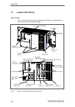
Fig. 3-1 shows the C230-2 module, indicating the interfaces and components on
the front panel (fault and status displays).
Labeling plate
Front view
without front covers
Measuring system
interfaces X3...X6
Front covers
(hinged)
Fault and
status displays
Drive
interface X2
Bus connector
for P-bus
SF
5 VDC
RUN
Mode selector
Connection for
power supply
X10
Mounting rail
I/O
interface X1
Front connector
X2
X3
X4
X5
X6
Ethernet interface X7
Memory module slot for
micro memory card
Rating plate
X1
PROFIBUS DP1
interface X8
Micro Memory Card (MMC)
STOPU
STOP
BUS1F
BUS2F
MRES
STOP
STOPU
RUN
Status displays
dig. inputs/outputs
PROFIBUS DP2/MPI
interface X9
SIEMENS
C230-2
M
L+
M
X8 DP1
X9 DP2/MPI
X7
24 VDC
Ejector for
Micro Memory Card
Ethernet address (MAC address)
Fig. 3-1
Position of interfaces and front panel components
Summary of Contents for SIMOTION C230-2
Page 16: ...Product Overview 1 16 E Siemens AG 2003 All rights reserved SIMOTION C230 2 04 2003 Edition ...
Page 70: ...Installation 4 70 E Siemens AG 2003 All rights reserved SIMOTION C230 2 04 2003 Edition ...
Page 124: ...Commissioning 8 124 E Siemens AG 2003 All rights reserved SIMOTION C230 2 04 2003 Edition ...
Page 130: ...Maintenance 9 130 E Siemens AG 2003 All rights reserved SIMOTION C230 2 04 2003 Edition ...


