


Assembly
5.5 Installing the machine
1MB..1/2/3/4 - shaft heights 63 ... 355
Operating Instructions, 06/2020, A5E44455710A
65
4.
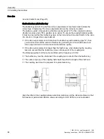
If necessary, rotate the machine into the right position so that the clearance holes in the
flange are central to the tapped holes.
5.
Lower the machine completely onto the mating flange so that it is fully in contact; then
remove the studs.
6.
Fix the machine using the flange fixing bolts.
5.5.3
Removing the rotor shipping brace
If a rotor shipping brace is attached to the machine, remove it at the last possible moment,
for example, when you are ready to push on the output or drive element.
Storing the rotor locking device
Store the rotor locking device in a safe place. It must be remounted if the machine is
removed and shipped on further.
Details relating to the alignment accuracy are provided in Section "Technical Data".
5.5.4
Recommended alignment accuracy
The alignment accuracy required depends essentially on the configuration of the overall
machine train. Observe the required alignment accuracy of the coupling manufacturer in all
cases when aligning the machine.
Table 5- 2
Recommended alignment accuracy
Speed
rpm
Parallel offset
mm
Angular offset
mm per 100 mm coupling diameter
750
0.09
0.09
1500
0.06
0.05
3000
0.03
0.025