


6.3.3
Terminal box 1XB1631
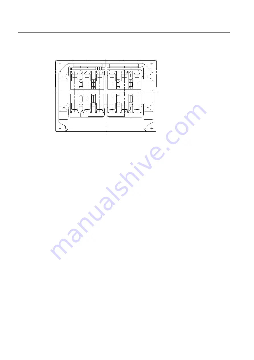
Figure 6-4
Terminal box 1XB1631
The connecting cables are introduced into the 1XB1631 terminal box through cable glands with
threaded holes 4 x M80 x 2 and 2 x M25 x 1.5. The cable glands are not included in the standard
scope of supply. The version with onion sealing ring is optional.
You can find additional information here:
● Bringing cables into the terminal box 1XB... with cable gland (Page 88)
● Connecting cables without cable lugs (Page 90)
● Connecting cables with cable lugs (Page 89)
See also
Bringing cables into the terminal box 1XB... with sealing insert with break-off ring (Page 87)
Electrical connection
6.3 Terminal box
SIMOTICS FD 1LH1
76
Operating Instructions 01/2019
Summary of Contents for SIMOTICS FD 1LH1
Page 2: ...23 01 2019 19 26 V11 01 ...
Page 28: ...Description SIMOTICS FD 1LH1 28 Operating Instructions 01 2019 ...
Page 122: ...Operation 8 10 faults SIMOTICS FD 1LH1 122 Operating Instructions 01 2019 ...
Page 140: ...Maintenance 9 2 Corrective Maintenance SIMOTICS FD 1LH1 140 Operating Instructions 01 2019 ...
Page 162: ...Disposal 11 5 Disposal of components SIMOTICS FD 1LH1 162 Operating Instructions 01 2019 ...
Page 164: ...Service and Support SIMOTICS FD 1LH1 164 Operating Instructions 01 2019 ...
Page 168: ...Quality documents SIMOTICS FD 1LH1 168 Operating Instructions 01 2019 ...
Page 173: ......