10.7
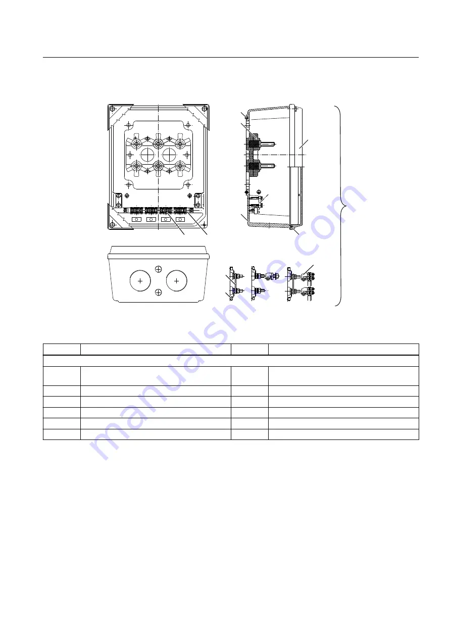
Terminal box GT640
Figure 10-4
Terminal box GT640
Table 10-4
Terminal box GT640
Part
Description
Part
Description
20.00 Terminal box without cable entry comprising the following components:
20.20
Housing
21.61
Terminals for auxiliary circuits, max. connection
2.5 mm
2
20.27
Mounting rail
22.01
Saddle terminal, complete
20.28
Seal
22.11
Connecting plate with internal cable
20.30
Cover
22.40
Terminal link (two holes)
20.38
Seal
22.70
Fixing lug for PE conductor
21.20
Bushing insulator
The terminal box can only be ordered as one component.
The maximum connection cross-section for the main circuit is 240 mm
2
.
Spare parts
10.7 Terminal box GT640
SIMOTICS FD 1LH1
Operating Instructions 01/2019
147
Summary of Contents for SIMOTICS FD 1LH1
Page 2: ...23 01 2019 19 26 V11 01 ...
Page 28: ...Description SIMOTICS FD 1LH1 28 Operating Instructions 01 2019 ...
Page 122: ...Operation 8 10 faults SIMOTICS FD 1LH1 122 Operating Instructions 01 2019 ...
Page 140: ...Maintenance 9 2 Corrective Maintenance SIMOTICS FD 1LH1 140 Operating Instructions 01 2019 ...
Page 162: ...Disposal 11 5 Disposal of components SIMOTICS FD 1LH1 162 Operating Instructions 01 2019 ...
Page 164: ...Service and Support SIMOTICS FD 1LH1 164 Operating Instructions 01 2019 ...
Page 168: ...Quality documents SIMOTICS FD 1LH1 168 Operating Instructions 01 2019 ...
Page 173: ......


