


Mounting
5.3 Attaching the output elements
SIMOTICS A-1FV5/1PV5 synchronous/induction motors
32
Operating Instructions, 03/2014, 610.45002.40
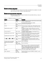
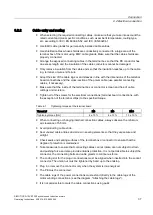
Balancing
The motors are balanced so that when they are shipped, they correspond to vibration
severity grade A in accordance with EN60034-14 over the complete speed range.
The motors are fitted with a key; this means that they are dynamically balanced with half a
key. The balancing type is marked on the DE shaft end with "H" (half key).
Note
Note the designation of the balancing type on the shaft end face. Plain or toothed shaft ends
are not marked.
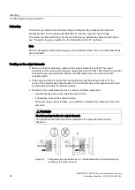
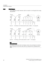
Pushing on the output elements
●
Make sure that the balancing method of the output element is correct! The output
elements must be balanced to balance quality grade G2.5 to ISO 1940. Rotary forces that
exceed this are not permissible. Please note that rotary forces can also occur with
coupling output.
●
If the output element is shorter than the feather key with balancing method "H", the
section of the feather key that protrudes from the shaft contour and output element must
be removed to maintain the balance quality.
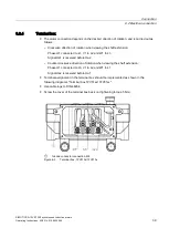
●
Fit/remove the output elements only by means of suitable equipment:
–
Use the threaded hole in the shaft extension (front).
–
If necessary, heat up the output element.
–
When removing output elements, use a washer to maintain the centering in the shaft
extension.
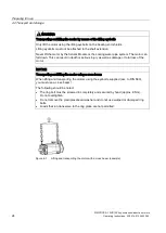
WARNING
Shock-hazard protection for output elements
The general shock-hazard protection measures for output elements must be
observed.
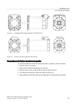
Figure 5-2
Fitting/removing output elements; A = intermediate washer (for maintaining the
centering in the shaft extension)


