Siemens simatic s7-400 FM 450-1 User Manual Download Page 110

Errors and diagnostics 


11.5 Operator error 


Counter module FM 450-1 

110


Manual, 02/2014, A5E03648739-02 

Diagnostic Data Records DS0 and DS1 

The information as to which event triggered a diagnostic interrupt is stored in diagnostic data 

records DS0 and DS1. Diagnostics data record DS0 consists of 4 bytes; DS1 consists of 

12 bytes, the first 4 bytes of which are identical to DS0.  

Reading the data record from the module 

Diagnostic data record DS0 is automatically transferred to the start information when the 

diagnostic OB is called. These four bytes are stored there in the local data element 

(bytes 8-11) of OB 82.   
You can read out the diagnostic data record DS 1 and hence also the contents of DS0 from 

the module using FC DIAG_INF. This is only useful if DS0 signals an error in one channel. 

Assignment of the Diagnostic Data Record DS0 and the Start Information 

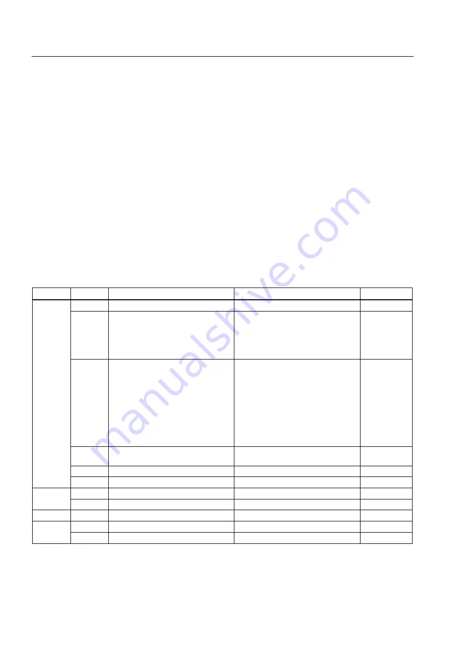
The table below shows the assignment of the diagnostic data record DS0 in the start 

information. All bits not listed have no meaning and are zero. 

Table 11- 1  Assignment of diagnostic data record DS0 

Byte 

Bit 

Meaning 

Remark 

Event no. 

Module error 

Is set at each diagnostic event. 

8:x:00 

Internal error 

Is set for all internal faults: 


Fault in RAM TEST 


Watchdog timeout 


Lost hardware interrupt 

8:x:01 

External error 

Is set for all external faults: 


Auxiliary voltage 1L+/1M is not 

connected or 5.2 VDC encoder 

supply is short circuited 


5.2 VDC encoder supply short 

circuited or overloaded. 


5V signals faulty 


Faulty parameter assignment 

8:x:02 

Error in one channel  

1 is always assigned for internal and 

external faults. 

8:x:03 

External auxiliary voltage faulty 


8:x:04 

Faulty parameter assignment 


8:x:07 

0 ... 3 

Type class  

Always assigned with 8. 


Channel information  

Always assigned with 1. 


Watchdog timeout 


8:x:33 

RAM defective 


8:x:43 

Hardware interrupt lost 


8:x:46 

Summary of Contents for simatic s7-400 FM 450-1

Page 1: ...______ ___________________ ___________________ ___________________ SIMATIC S7 400 Counter module FM 450 1 Manual 02 2014 A5E03648739 02 Preface Product Overview 1 This is how the FM 450 1 counts 2 Installation and Removal 3 Wiring 4 Parameter assignment 5 Program 6 Commissioning 7 Modes settings parameters and commands 8 Encoder signals and their evaluation 9 Assignment of the DB 10 Errors and dia...

Page 2: ...y personnel qualified for the specific task in accordance with the relevant documentation in particular its warning notices and safety instructions Qualified personnel are those who based on their training and experience are capable of identifying risks and avoiding potential hazards when working with these products systems Proper use of Siemens products Note the following WARNING Siemens products...

Page 3: ...e FM 450 1 valid at the time the manual is published We reserve the right to describe changes to the functions of the FM 450 1 in the form of product information Standards The S7 400 automation system meets the requirements and criteria of IEC 61131 2 Recycling and disposal Owing to the fact that its equipment is low in contaminants the FM 450 1 can be recycled For environmentally compliant recycl...

Page 4: ... automation support request Service Support on the Internet In addition to our documentation we offer a comprehensive online knowledge base on the Internet at Industry Automation and Drive Technologies Homepage http www siemens com automation service support There you will find the following information for example The newsletter that provides up to date information on your products The documents ...

Page 5: ...pter overview 23 3 2 Preparing for Mounting 24 3 3 Installing the FM 450 1 25 3 4 Removal of the FM 450 1 26 4 Wiring 27 4 1 Chapter overview 27 4 2 Terminal assignment of the front connector 28 4 3 Wiring Front Connectors 35 4 4 Module status after power is switched on 39 5 Parameter assignment 41 5 1 Chapter overview 41 5 2 Installing and calling parameter assignment screen forms 42 6 Program 45...

Page 6: ...havior of the digital outputs 76 8 9 Setting Pulse duration 79 8 10 Command Open and close gate 80 8 11 Command Set counter 83 8 12 Initiating a process interrupt 90 9 Encoder signals and their evaluation 93 9 1 Chapter overview 93 9 2 Encoders which can be connected 94 9 3 5 V differential signals 95 9 4 24 V signals 97 9 5 Signal evaluation 100 10 Assignment of the DB 103 10 1 Assignment of the ...

Page 7: ...Table of contents Counter module FM 450 1 Manual 02 2014 A5E03648739 02 7 13 Spare parts 119 14 References 121 Glossary 123 Index 127 ...

Page 8: ...Table of contents Counter module FM 450 1 8 Manual 02 2014 A5E03648739 02 ...

Page 9: ...tion provides you with an overview of the FM 450 1 function module It informs you of what the FM 450 1 can do Examples demonstrate some of the possible applications of the FM 450 1 You will learn how the FM 450 1 is integrated into the S7 400 automation system and familiarize yourself with the vital components of FM 450 1 ...

Page 10: ...unting You can start and stop the count either via the user program software gate or via external signals hardware gate Comparison values You can store two comparison values per counter on the module they are assigned to the two corresponding outputs on the module If the counter status reaches one of the comparison values then the output assigned to it can be set so that it triggers control operat...

Page 11: ... and 500 ms for the pulse duration This value applies to both outputs By prescribing a pulse duration you can adapt the FM 450 1 to existing actors Which signals can the FM 450 1 count The FM 450 1 can count signals that are generated by the following encoders Incremental 5 V encoders Incremental 24 V encoders 24 V pulse encoders with direction level 24 V initiators without direction level e g lig...

Page 12: ...r an FM450 1 Here a specific number of parts is to be filled into a box An FM 450 1 counter assumes the job of counting the parts and controlling the two motors for transporting the parts and the box If the box is in the right position belt A is stopped via the light barrier the counting process is started and the motor for belt B switched on If the programmed number of parts are in the box the FM...

Page 13: ... of module The illustration shows the FM 450 1 module with front connector plugged in Figure 1 2 Illustration of the FM 450 1 Order number and version The full order number of the FM 450 1 is shown on the rating plate The abbreviated order number and the version of the FM 450 1 are marked on the top end of the front of the module ...

Page 14: ...counting backwards CH1 IN 0 CH2 IN 0 Green Status of input 1I0 of counter 1 and or 2I0 of counter 2 CH1 IN 1 CH2 IN 1 Green Status of input 1I1 of counter 1 and or 2I1 of counter 2 CH1 IN 2 CH2 IN 2 Green Status of input 1I2 of counter 1 and or 2I2 of counter 2 CH1 OUT 0 CH2 OUT 0 Green Status of output 1Q0 of counter 1 and or 2Q0 of counter 2 CH1 OUT 1 CH2 OUT 1 Green Status of output 1Q1 of coun...

Page 15: ...or coding If you hook in the front connector the front connector coding engages Thereafter this front connector can only be attached to an FM 450 1 module Labeling strips A plate block with four labeling strips is included with the module These strips can be labeled individually with the corresponding signal names ...

Page 16: ... includes Parameterization software with parameterization interfaces Software for the CPU blocks Documentation parameter assignment screen forms The FM 450 1 is adapted to the respective task via parameters These parameters are stored in an SDB and transferred to the module by the CPU The parameters can be determined via the parameter assignment screen forms These parameter assignment screen forms...

Page 17: ...RL function which is invoked in the CPU user program This FC enables communication between the CPU and the FM 450 1 In addition there is also the FC DIAG_INF for the FM 450 1 with which you can transmit diagnostic data into the DB of FC CNT_CTRL This figure shows an S7 400 layout with an FM 450 1 and several signal modules Figure 1 3 Layout of a SIMATIC S7 400 with an FM 450 1 ...

Page 18: ...Product Overview 1 5 The FM 450 1 software Counter module FM 450 1 18 Manual 02 2014 A5E03648739 02 ...

Page 19: ...counting is to begin This initial value is the load value You can specify any value within the count limits for the load value Comparison values You can use two digital outputs on the module for each counter in order to trigger reactions in a process at a certain counter reading independently of the CPU You store two comparison values for each counter on the FM 450 1 If the counter reading reaches...

Page 20: ...s reached the low count limit and a further count pulse comes then it jumps to the high count limit and then goes on counting down from there Single counting For single counting the counter starts from the load value If when counting up a counter has reached the high count limit and a further count pulse comes then the counter jumps to the low count limit and comes to a halt even if further count ...

Page 21: ...hen counting up the counter reaches the high count limit and further count pulses come then the counter jumps to the load value and starts totalizing the count pulses Figure 2 3 Periodic counting in the up direction If when counting down a counter has reached the low count limit and a further count pulse comes then the counter jumps to the load value and then continues counting down from there ...

Page 22: ...h is controlled via the user program in the CPU A hardware gate HW gate that is controlled via the 1I0 and 1I1 counter 1 and or 2I0 and 2I1 counter 2 digital inputs on the module When assigning parameters for the FM 450 1 you determine if the operation of the hardware gate is to be level controlled or edge controlled Example When the gate signal is set the gate is opened and the count pulses are c...

Page 23: ...w In this chapter you will find information on the installation and removal of the FM 450 1 You will find out what you have to pay attention to during installation You will obtain information on project planning and on the design of an FM 450 1 Step by step you will be shown how to install and remove the FM 450 1 ...

Page 24: ...signal module in any central device or extension device Designing the mechanical structure Manual 1 provides you with information on how the mechanical structure can be designed and how to proceed Define start address The start address of the FM 450 1 is required for the purpose of communication between the CPU and the FM 450 1 The start address is entered into the DB of the FC CNT_CTRL refer to c...

Page 25: ...tion procedure Proceed as follows to install an FM 450 1 1 Hook the FM 450 1 in at the top and rotate it down 2 Screw the FM 450 1 tight torque approx 0 8 to 1 1 Nm 3 Label the FM 450 1 with its slot number For this purpose use the number wheel enclosed with the rack The system according to which you must perform then numbering and the procedure for defining the slot number are described in manual...

Page 26: ...he FM 450 1 Tools required You require a 4 5 mm screwdriver to remove the FM 450 1 Procedure for removal Proceed as follows to remove an FM 450 1 1 Release the front connector and pull it out 2 Undo the module fixing screw 3 Rotate the module out of the rack and unhook it 4 If necessary install a new module Further information Further information on the installation and removal of modules is to be...

Page 27: ...pter overview In this chapter you will find information on wiring the FM 450 1 Terminal assignment of the front connector Terminal functions Notes on the selection of cables Procedure when wiring the front connector State of module after it has been wired and the power supply is switched on ...

Page 28: ...the front connector Front connectors You connect the following to the 48 pin front connector count signals digital inputs digital outputs encoder power supply auxiliary voltage and load voltage The following illustration shows the front side of the front connector the strip with the terminal assignment printed on and the labeling strips ...

Page 29: ...Wiring 4 4 Module status after power is switched on Counter module FM 450 1 Manual 02 2014 A5E03648739 02 29 Figure 4 1 Front connector of the FM 450 1 ...

Page 30: ...der signal B 8 1 B ON Encoder signal B 9 1 N ON Encoder signal N 10 1 N ON Encoder signal N 11 1 A ON Encoder signal A 12 1 B ON Encoder signal B Directional signal 13 1 N ON Encoder signal N 14 1M OFF Ground for encoder power supply 15 5 2 VDC OFF 5 2 V encoder power supply 16 24 VDC OFF 24 V encoder power supply Counter 2 17 2 A ON Encoder signal A 18 2 A ON Encoder signal A 19 2 B ON Encoder si...

Page 31: ...Q0 46 2Q1 OFF Digital output 2Q1 47 2L ON 24 V load voltage for the digital inputs and outputs 48 2M ON Load voltage ground for digital inputs and outputs Note The circuits for the counter inputs encoder power supply encoder signals are isolated electrically toward the ground of the CPU Hence you must connect terminal 4 1M to the ground of the CPU with a low impedance If you supply the encoders wi...

Page 32: ...RS422 i e incremental encoders with the differential signals A and A B and B N and N The A and A B and B N and N signals are connected via the correspondingly labeled terminals The signals N and N are only to be connected if you wish to set the counter to the zero mark of the encoder The inputs are not electrically isolated from the S7 400 bus 24 V encoder signals A B and N 24 V signals are identi...

Page 33: ...the gate control of counter 2 The gates can be operated both in the level controlled and edge controlled modes see chapter Modes settings parameters and commands Page 65 The 1I2 digital input is for setting counter 1 to the load value The 2I2 digital input is for setting counter 2 to the load value The digital inputs are operated with a 24 V nominal voltage The digital inputs are electrically isol...

Page 34: ...rrent of 0 5 A They are protected against overload and short circuit Note The direct connection of relays and cutouts can be executed without external wiring The time related behavior of the digital outputs depends on the parameter assignment and is described in greater detail in the chapter Setting Behavior of the digital outputs Page 76 2L 2M load voltage To ensure the power supply of the digita...

Page 35: ...for the digital inputs must be shielded The cables for the count signals must be shielded You must apply the shields to the count signal cables both on the pulse encoder and in close proximity to the module e g via the shield application element Cables A and A B and B N and N of the incremental 5 V encoder must be twisted in pairs The following figure shows details relating to the connection of in...

Page 36: ...5 V encoders Terminal 4 1M of the front connector must be connected with the ground of the CPU with a low impedance If you supply the encoder with external voltage you must also connect the ground of this external voltage supply to the ground of the CPU The following figure shows details relating to the connection of incremental 24 V encoders ...

Page 37: ... If the encoder is supplied via the module the cable cross section must be selected large enough for sufficient voltage to be applied to the encoder via the cable in spite of a drop in voltage This applies in particular in the case of incremental 5 V encoders A wire end ferrule is not required If you use wire end ferrules they must be of the type without insulating collars in compliance with DIN 4...

Page 38: ...1 Pull the cover off the front connector 2 Insulate the cables length 6 mm 3 Do you use wire end ferrules If so Press fit the wire end ferrules with the the conductors 4 Load the enclosed strain relief clamp into the front connector 5 Start wiring from the bottom If you have a front connector with screw type contacts also screw unassigned terminals torque 0 6 to 0 8 Nm 6 Tighten the strain relief ...

Page 39: ... 0 to 32 bit counting range Counter status zero Counter setting with digital input 1I2 or 2I2 and zero mark disabled Input delay for the digital inputs typically 1 μs max frequency 200 kHz minimum pulse width 2 5 μs Input delay for 24 V count inputs typically 1 μs max frequency 200 kHz minimum pulse width 2 5 μs Outputs 1Q0 and 1Q1 or 2Q0 and 2Q1 switched off Pulse duration 0 No Hardware interrupt...

Page 40: ...Wiring 4 4 Module status after power is switched on Counter module FM 450 1 40 Manual 02 2014 A5E03648739 02 ...

Page 41: ...t 5 5 1 Chapter overview Chapter overview In this chapter you will learn how to install and start parameter assignment screen forms The parameter assignment screen forms have an integrated help function to support you with parameter assignment and commissioning of the FM 450 1 ...

Page 42: ...ow the operating instructions provided by the installation program Important information can be found in the readme file Result The components of the configuration package are installed in the following directories SIEMENS STEP7 S7LIBS FMx501LIB FCs UDTs SIEMENS STEP7 S7FCOUNT Configuration software Readme Online Help SIEMENS STEP7 EXAMPLES Examples SIEMENS STEP7 S7MANUAL S7FCOUNT Getting Started ...

Page 43: ...ead this file with the WORDPAD editor in Windows Calling parameter assignment screen forms The parameter assignment screen forms are displayed automatically after successful installation if you assign the FM 450 1 parameters within the hardware configuration Calling the integrated help There is an integrated online help for the parameter assignment screen forms that you can call in any phase of pa...

Page 44: ...Parameter assignment 5 2 Installing and calling parameter assignment screen forms Counter module FM 450 1 44 Manual 02 2014 A5E03648739 02 ...

Page 45: ...r integrating the FM 450 1 into a user program and make handling the desired functions as easy as possible for you This chapter describes these blocks Block number Block name Meaning FC 0 CNT_CTRL Controlling the FM 450 1 counters FC 1 DIAG_INF Read diagnostic data set of the FM 450 1 In addition an example program demonstrates how to use the blocks The example program shows how to call the blocks...

Page 46: ... address to the DB in the user program so that the assignment of the module address occurs when user program is called in OB 100 see example below Alternative procedure You can have the module address entered automatically when you select the module in HW Config open the Properties dialog box with the menu command Edit Object Properties and select the DB using the Mod Addr button there However in ...

Page 47: ...for channel 2 You program the transfer in STL as follows STL Channel 1 L 512 Module address 512 T FM450_DB_K1 MOD_ADR Transfer of module address L P 512 0 Module address in pointer format T FM450_DB_K1 CH_ADR Transfer of the channel address for channel 1 L 32 User data interface length 32 T FM450_DB_K1 U_D_LGTH Transfer of the user data interface length Channel 2 L 512 Module address 512 T FM450_D...

Page 48: ...ers this queries this SW_GATE INPUT BOOL SW gate start stop counter control bit sets and resets this queries this GATE_STP INPUT BOOL Stop gate counter control bit sets and resets this queries this OT_ERR_A INPUT BOOL Acknowledge operator error sets and resets this queries this OT_ERR OUTPUT BOOL Operator error occurred queries this sets and resets this L_DIRECT IN OUT BOOL Trigger bit for direct ...

Page 49: ...out parameter L_DIRECT L_PREPAR T_CMP_V1 T_CMP_V2 RES_SYNC and RES_ZERO is deleted again by the FC CNT_CTRL after the job has been completed This enables you to recognize that the job has been completely executed by the FM 450 1 and if necessary to evaluate this information in the user program Startup characteristics As soon as the FC CNT_CTRL identifies a startup CPU or FM startup a pending job i...

Page 50: ...on has been performed the initiation parameter IN_DIAG is reset and hence the transfer is reported as completed A full description of the SFC RD_REC is to be found in manual 2 Call The FC DIAG_INF can be called in the cycle and in the interrupt program However it is not expedient to call it in the time controlled program Calling the FC DIAG_INF in the STL and LAD representations is rendered below ...

Page 51: ...ATE_STOP Stop GATE OT_ERR_A ERROR_ACKN Acknowledge operator error OT_ERR OPERATOR_ERR Operator error occurred L_DIRECT LOAD_DIRECT Load new counter value L_PREPAR LOAD_INDIRECT Prepare new counter value T_CMP_V1 COMP1_LOAD Load new comparison value 1 T_CMP_V2 COMP2_LOAD Load new comparison value 2 RES_SYNC RES_SYNCHRO Delete synchronization status bit RES_ZERO RES_ZERO Delete zero crossing status ...

Page 52: ...o be transferred must have been entered in the DB 1 The load value is transferred and started When the FC is called the load value of a channel is transferred to the FM 450 1 Calling the FC CNT_CTRL selects either the L_DIRECT parameter or the L_PREPAR parameter The L_DIRECT selection bit specifies that the load value will be loaded directly onto the counter L_DIRECT 1 The L_PREPAR selection bit s...

Page 53: ...ocks Table 6 2 Technical Specifications FC CNT_CTRL FC DIAG_INF Block number FC 0 FC 1 Version 3 0 3 0 Assignment in work memory 540 bytes 246 bytes Assignment in load memory 634 bytes 326 bytes Assignment in local data area 4 bytes 38 bytes System function called SFC 51 RDSYSST Internal update time of the FM 450 1 0 5 ms SDB 100 approx 240 bytes ...

Page 54: ...Program 6 5 Technical specifications of the blocks Counter module FM 450 1 54 Manual 02 2014 A5E03648739 02 ...

Page 55: ...55 Commissioning 7 7 1 Chapter overview Chapter overview In this chapter you will find checklists for commissioning the FM 450 1 These checklists enable you to check all working steps up to full operation of the module avoid operating faults by the module ...

Page 56: ...r Select cables Observe rules and specifications in chapter Wiring Page 27 Connect 5 V encoders Counter 1 Terminal Name Function 5 V incremental encoders with differential signals A and A B and B N and N 14 15 5 6 7 8 9 10 1M 5 2 VDC A A B B N N Ground for encoder power supply 5 2 V encoder power supply Encoder signal A Encoder signal A Encoder signal B Encoder signal B Encoder signal N Encoder si...

Page 57: ...nal N Counter 1 Terminal Name Function 24V pulse encoder without direction level initiator BERO 14 16 11 1M 24 VDC A Ground for encoder power supply 24 V encoder power supply Encoder signal A Counter 2 Terminal Name Function 24V pulse encoder without direction level initiator BERO 26 28 23 1M 24 VDC A Ground for encoder power supply 24 V encoder power supply Encoder signal A Counter 1 Terminal Nam...

Page 58: ...TART Digital input STOP Digital input SET Digital output Q0 Digital output Q1 Counter 2 Terminal Name Function Digital inputs and outputs 41 42 43 45 46 2I0 2I1 2I2 2Q0 2Q1 Digital input START Digital input STOP Digital input SET Digital output Q0 Digital output Q1 Connecting auxiliary voltage and load voltage Terminal Name Function Encoder supply 3 4 1L 1M 24V auxiliary voltage Auxiliary voltage ...

Page 59: ...tions procedure X Assign the FM 450 1 parameters Select encoders for counter 1 5 V encoder with symmetrical signals Monitoring A B N A B A None 24 V encoder with asymmetrical signals Interface Sinking output Sourcing output push pull Frequency range minimum pulse width 200 kHz 2 5 μs 20 kHz 25 μs 24V encoders with a pulse train and direction signal Interface Current sinking output Current sourcing...

Page 60: ...pulse width 200 kHz 2 5 μs 20 kHz 25 μs 24 V encoder with a pulse train and direction signal Interface Current sinking output Current sourcing output push pull Frequency range minimum pulse width 200 kHz 2 5 μs 20 kHz 25 μs 24 V initiator Signal evaluation Single Double Quadruple Frequency and direction with 24 V encoders Step Options procedure X Assign the FM 450 1 parameters Specify mode for cou...

Page 61: ...Periodic counting With SW gate With HW gate Set count range 0 to 32 bit 31 bit to 31 bit Specify the behavior of the digital inputs for counter 1 HW gate Level controlled Edge controlled Minimum pulse width 2 5 μs 25 μs Set counter Single setting Multiple setting Evaluate zero mark for setting Specify the behavior of the digital inputs for counter 2 HW gate Level controlled Edge controlled Minimum...

Page 62: ...e for pulse duration when comparison value 2 is reached in down direction Active for pulse duration when comparison value 2 is reached in up or down direction Pulse duration 0 to 500 ms Specify the behavior of the digital outputs for counter 2 Output 2Q0 Disable Active from comparison value 1 to overflow Active from comparison value 1 to underflow Active for pulse duration when comparison value 1 ...

Page 63: ...nderflow Interrupt in case of zero crossing Interrupt when comparison value 1 is reached in the up direction Interrupt when comparison value 1 is reached in the down direction Interrupt when comparison value 2 is reached in the up direction Interrupt when comparison value 2 is reached in the down direction Interrupt when setting counter Select interrupts for counter 2 Interrupt when door is opened...

Page 64: ...Commissioning 7 3 Working steps for parameter assignment Counter module FM 450 1 64 Manual 02 2014 A5E03648739 02 ...

Page 65: ...iew Chapter overview This chapter gives you an overview of the three modes the various settings and the commands available and how to call them A description of the three modes A description of the settings A description of the two commands Marginal conditions and notes which you must heed when using these functions ...

Page 66: ...s The default setting is the Continuous counting mode Choice of count range behavior of the two digital outputs pulse duration evaluation of the count signals and the selection of the signal to set the counter all depend on the mode Which settings are available You can adapt the FM 450 1 to your count job by means of the following five settings Table 8 2 The FM 450 1 settings Name Description Coun...

Page 67: ...define the basic parameter assignment of each FM 450 1 The following table shows the significance of the relevant parameters Table 8 4 Parameters for the basic parameter assignments Name Option Description Interrupt selection None You enable the corresponding interrupts via this selection Diagnostics Process Process and diagnostics Reaction to a CPU STOP STOP Outputs immediately disabled counting ...

Page 68: ...rated via hardware signals which are connected to the front connector or by setting the relevant input parameters of the FC CNT_CTRL in the user program to influence the count process The input parameters are stored as control bits in the DB of the FC CNT_CTRL Control and status bits in the DB In addition to the control bits there are status bits in the DB which signalize the status of the count p...

Page 69: ...nting down if the counter reaches the lower count limit and a further count pulse comes it jumps to the upper limit and continues counting from there without any pulse loss Select gate function In this mode you can select the gate function Options Without gate default SW gate HW gate level controlled or edge controlled Figure 8 1 Infinite counting with load value and gate function Open and close S...

Page 70: ...plying signal to input 1I0 2I0 Closing HW gate level controlled Removing signal from input 1I0 2I0 Opening HW gate edge controlled Applying positive edge to input 1I0 2I0 Closing HW gate edge controlled Applying positive edge to input 1I1 2I1 When the HW gate opens the counter resumes counting from the current counter status Terminating counting process with the gate stop function In addition you ...

Page 71: ...p to the count limit Select gate function In this mode you can select the gate function Options SW gate HW gate level controlled or edge controlled Figure 8 2 Single counting with load value and gate function Open and close SW gate You open and close the SW gate and set the counter to the load value with the input parameter SW_GATE of the FC CNT_CTRL Action Initiating event Open SW gate Set SW_GAT...

Page 72: ...positive edge is again applied to input 1I1 2I1 the counter resumes counting from the load value irrespective of whether the gate is closed or still open retriggering provided input 1I1 2I1 is not set Behavior at count limits If the counter reaches the upper or lower count limit and another count pulse arrives the counter is set to the other count limit Thereafter the gate is closed and the counti...

Page 73: ...gate level controlled or edge controlled Figure 8 3 Periodic counting with load value and gate function Open and close SW gate You open and close the SW gate and set the counter to the load value by setting or resetting the relevant bit in the DB of the FC CNT_CTRL in the user program see chapter Assignment of the DB Page 103 When you open the SW gate the FM 450 1 starts counting from the load val...

Page 74: ...f in the case of an edge controlled HW gate a positive edge is again applied to input 1I0 2I0 the relevant counter again starts counting from the load value irrespective of whether the gate is closed or still open retriggering provided input 1I1 2I1 is not set Behavior at the Count Limits If a counter reaches the upper or lower count limit and a further count pulse comes it begins counting from th...

Page 75: ...the counter status changes from 4 294 967 295 to 0 When the counter status changes from 0 to 4 294 967 295 31 to 31 bit 2 147 483 648 to 2 147 483 647 8000 0000H to 7FFF FFFFH When the counter status changes from 2 147 483 647 to 2 147 483 648 When the counter status changes from 2 147 483 648 to 2 147 483 647 1 In this count range you can only specify and evaluate values in hexadecimal Overflow u...

Page 76: ... of the respective count range The comparison value is interpreted according to the selected count range If you give FFFF FFFF H for example as the comparison value the value is interpreted as 4 294 967 295 within the 0 to 32 bit count range and as 1 within the 31 to 31 bit count range Enabling the outputs Before you can activate the outputs you must first enable them by setting the appropriate bi...

Page 77: ...w Active between comparison value and overflow The output is activated when the counter is within the range between comparison value and underflow The output is activated by setting the counter to a value between the comparison value and underflow Active for pulse duration when the comparison value is reached in up direction The output is activated when the comparison value is reached in the up co...

Page 78: ... will be initiated A further pulse can only be initiated when the output is no longer active you want to assign the parameters for the output to be active for the pulse duration in the up counting direction you must not enable a hardware interrupt when the comparison value 1 or 2 in the down direction is reached you want to assign the parameters for the output to be active for the pulse duration i...

Page 79: ...tting is only effective if you preselect the behavior of the output accordingly The pulse duration is without effect if the output is to be set between the comparison value and overflow or underflow Pulse duration begins when the output is set Inaccuracy of the pulse duration is less than 1 ms Value range You can prescribe a value between 0 and 500 ms for the pulse duration This value applies to b...

Page 80: ...ify which gate you want to use for the count process The following figures demonstrate the various possibilities for opening and closing the FM 450 1 gates Level controlled opening and closing of the HW gate The following figure shows the level controlled opening and closing of the HW gate of counter 1 Figure 8 4 Level controlled opening and closing of the HW gate of counter 1 If you set input 1I0...

Page 81: ...dge on input 1I0 The door is closed by a positive edge on input 1I1 If positive edges occur simultaneously on inputs 1I0 and 1I1 an open gate is closed or a closed gate remains closed If input 1I1 is set a positive edge on input 1I0 cannot open the gate The same applies analogously to counter 2 inputs 2I0 and 2I1 Status of inputs 1I0 2I0 and 1I1 2I1 The status of the inputs 1I0 2I0 and 1I1 2I1 are...

Page 82: ... the FC CNT_CTRL Terminating the count with the gate stop function In addition you can terminate the counting process at any time using the gate stop function of the relevant counter irrespective of the signals applied or the status of the SW gate For this purpose you set the GATE_STP input parameter of the FC CNT_CTRL When you reset the GATE_STP parameter you can only open the gate for the counte...

Page 83: ...ods and the time sequence for setting a counter Load value Any number within the count range can be set for the load value The load value is interpreted according to the selected count range If for example you specify FFFF FFFF H as the load value this is interpreted as 4 294 967 295 within the count range 0 to 32 bit and as 1 within the count range 31 to 31 bit The load value is entered in the DB...

Page 84: ...ess Hence you achieve greater precision in the count process The counter is set independent of the mode After setting the counter with an external signal the STS_SYNC bit is set in the DB The STS_SYNC bit is cleared by the RES_SYNC bit Note The synchronization of a counter with the zero mark only makes sense if the gate is open When setting a counter with an external signal if you have only enable...

Page 85: ...ET_DN set The counter is only set in the case of down counting ENSET_UP and ENSET_DN set Counter is set for up and down counting Parameter assignment Behavior of the FM 450 1 Parameter assignment single setting of counter The counter is set only at the first rising edge at input 1I2 2I2 If the counter is to be set again you must first set ENSET_UP or ENSET_DN again The counter is then set again wi...

Page 86: ... analogous for counter 2 with input 2I2 In the case represented here only ENSET_UP is set i e the counter is set during up counting The relevant counter is set with the first rising edge at input 1I2 as long as ENSET_UP is set If you want to set this counter again first you must reset the relevant ENSET_UP and then set it again Then the next positive edge at input 1I2 results in the counter being ...

Page 87: ...1I2 result in the setting of the counter Figure 8 8 Multiple setting of counter 1 with input 1I2 Setting the counter with the zero mark If you assign the parameters for setting a counter with the zero mark of the encoder the relevant counter is set with the rising edge of the zero mark Setting is only performed if input 1I2 2I2 of the relevant counter is set at the time of the rising edge of the z...

Page 88: ...rk Note It is imperative that you set one of the two variables ENSET_UP or and ENSET_DN and input 1I2 2I2 so that the relevant counter can be set with the zero mark Single setting with the zero mark The following figure shows counter 1 being set once with the zero mark In the case represented here only ENSET_UP is set i e the counter is set during up counting The relevant counter is set with the f...

Page 89: ...igure shows multiple setting of counter 1 with the zero mark In the case represented here only ENSET_UP is set i e the counter is set during up counting The relevant counter is set with each first rising edge of the zero mark as long as ENSET_UP and input 1I2 are set The situation is analogous for counter 2 with input 2I2 Figure 8 10 Multiple setting of counter 1 with the zero mark ...

Page 90: ...hardware interrupt In the FM 450 1 count mode the following events can trigger a hardware interrupt independently of each other for each of the two counters Opening of the gate in modes with HW or SW gate Closing of the gate in modes with HW or SW gate Overflow Underflow Zero crossing Reaching comparison value 1 in the up direction Reaching comparison value 1 in the down direction Reaching compari...

Page 91: ...ormation on the event that initiated the hardware interrupt is entered into these four bytes The following table shows which bits are set for which interrupt All bits not listed have no meaning and are zero Byte Bit Significance Interrupt in the case of Counter 1 0 0 Opening the gate 1 Closing the gate 2 Overflow 3 Underflow 4 Reaching comparison value 1 in the up direction 5 Reaching comparison v...

Page 92: ... event occurs that is to trigger a hardware interrupt and the same previous event has not yet been acknowledged no further hardware interrupt is triggered the hardware interrupt is lost This can result in the diagnostic interrupt hardware interrupt lost depending on the parameters assigned Default setting No hardware interrupt is assigned in the default setting ...

Page 93: ...verview Chapter overview This chapter describes which encoders you can connect to the counter module the time profile of the encoder signals the multiple evaluation of encoder signals by the counter module how the module monitors the various encoder signals which signals can be assigned input filter parameters ...

Page 94: ...plitude and number of signals Pulse generators such as light barriers or proximity switches BEROs return only a rectangular signal at a specific amplitude Connecting different encoders The counter module supports different encoders which return pulses for the count signals The table shows these encoders and the corresponding signals Table 9 1 Encoders which can be connected Encoders Signal 5 V inc...

Page 95: ...ting Track N is used to initialize the counter with the load value if programmed accordingly Encoders featuring these six signals are symmetrical encoders The diagram shows the time profile of the encoder signals Figure 9 1 Signals of the 5 V incremental encoder The module detects the count direction by evaluating the ratio of signals A and B The diagrams in the chapter Signal evaluation Page 100 ...

Page 96: ... signal pairs if you have disabled the corresponding diagnostics functions in the program monitoring An error state at all three signals indicates a defective encoder or a short circuit at the 5 2 V DC encoder supply or a missing encoder When programming is completed and the module detects an error the error information will be written to the diagnostics data records DS0 and DS1 This situation my ...

Page 97: ...d accordingly Encoders which do not return inverted signals asymmetrical encoders The diagram shows the time profile of the encoder signals Figure 9 2 Signals of the 24 V incremental encoder The module detects the count direction by evaluating the ratio of signals A and B The diagrams in the chapter Signal evaluation Page 100 show which edges of the A and B signals are incremented or decremented Y...

Page 98: ...rofile of the encoder signals and the resultant count pulses Figure 9 3 Signals of a 24 V pulse generator with direction signal Programming the encoder inputs The count direction is defined by programming the encoder inputs The diagram shows a change of the count direction based on parameter settings Table 9 2 Count direction determined by input parameters Programming Terminal B Count direction cu...

Page 99: ... the 24 V inputs A B and N and for the digital inputs Input filters available Table 9 3 Input filters Features Input filter 1 default Input filter 2 Typical input delay 1 µs 15 µs Maximum count frequency 200 kHz 20 kHz Minimum pulse width of count signals 2 5 µs 25 µs Monitoring encoder signals The 24 V count signals are not monitored to detect wire breaks or short circuits Coding plug only for FM...

Page 100: ...adruple evaluation Multiple evaluation is only supported for 5 V incremental encoders which return the A and B signal with a phase shift of 90 for 24 V incremental 24 V encoders with a phase shift of 90 of the A and B signals Single evaluation In this mode the module evaluates only one edge of signal A Up count pulses are recorded at the positive edge at track A and if track B is low Down count pu...

Page 101: ...unt direction i e the up or down count pulse The diagram shows the double evaluation of signals Figure 9 5 Double evaluation Quadruple evaluation Quadruple evaluation refers to the evaluation of the positive and negative edges of signals A and B The logic level at the signals A and B determines the count direction i e the up or down count pulse The diagram shows quadruple evaluation of signals Fig...

Page 102: ...Encoder signals and their evaluation 9 5 Signal evaluation Counter module FM 450 1 102 Manual 02 2014 A5E03648739 02 ...

Page 103: ...le 10 1 Assignment of the DB Address Variable Data type Initial value Comment 0 0 AR1_BUFFER DWORD DW 16 0 AR1 buffer 4 0 FP BYTE B 16 0 Flag byte 5 0 RESERVED BYTE B 16 0 Reserved 6 0 MOD_ADR WORD W 16 0 Module address 8 0 CH_ADR DWORD DW 16 0 Channel address 12 0 U_D_LGTH BYTE B 16 0 User data length 13 0 A_BYTE_0 BYTE B 16 0 Reserved 14 0 LOAD_VAL1 DINT L 0 New load value write user 18 0 CMP_V1...

Page 104: ...A_BIT3_5 BOOL FALSE Reserved 29 6 A_BIT3_6 BOOL FALSE Reserved 29 7 A_BIT3_7 BOOL FALSE Reserved 30 0 LATCH_LOAD1 DINT L 0 Current load or latch value read user 34 0 ACT_CNTV1 DINT L 0 Current count value read user 38 0 DA_ERR_W1 WORD W 16 0 Data error word read user 40 0 OT_ERR_B1 BYTE B 16 0 Operator error byte read user 41 0 E_BIT0_0 BOOL FALSE Reserved 41 1 STS_TFB BOOL FALSE Status test free ...

Page 105: ...E Reserved 46 0 ACT_CMP11 DINT L 0 Current comparison value 1 read user 50 0 ACT_CMP21 DINT L 0 Current comparison value 2 read user The following diagnostics data are entered by the FC_DIAG_INF 54 0 MDL_DEFECT BOOL FALSE Module faults 54 1 INT_FAULT BOOL FALSE Internal error 54 2 EXT_FAULT BOOL FALSE External error 54 3 PNT_INFO BOOL FALSE Channel error 54 4 EXT_VOLTAGE BOOL FALSE Auxiliary volta...

Page 106: ...signal A 62 1 CH1_SIGB BOOL FALSE Channel 1 error signal B 62 2 CH1_SIGZ BOOL FALSE Channel 1 error zero signal 62 3 CH1_BETW BOOL FALSE Channel 1 error between channels 62 4 CH1_5V2 BOOL FALSE Channel 1 5 2 V encoder supply fault 62 5 D_BIT8_5 BOOL FALSE DS1 byte 8 bit 5 62 6 D_BIT8_6 BOOL FALSE DS1 byte 8 bit 6 62 7 D_BIT8_7 BOOL FALSE DS1 byte 8 bit 7 63 0 D_BYTE9 BYTE B 16 0 DS1 byte 9 64 0 CH...

Page 107: ... following classes on the module Faults displayed by the diagnostics LEDs that indicate internal and external module faults Faults that can trigger a diagnostics interrupt Operator errors caused by incorrect operation The different classes of errors are indicated and displayed in different positions and must be acknowledged in different ways This chapter describes which errors and faults can occur...

Page 108: ...chdog has responded Module replacement Process interrupt lost Is acknowledged by processing the process interrupt External fault EXTF Diagnostics LED Auxilliary voltage 1L 1M is not connected or 24 VDC encoder supply is short circuited Correct connection 5 2 VDC encoder supply short circuited or overloaded Correct connection 5 V encoder signals faulty wire breakage short circuit cable missing Corr...

Page 109: ...meout RAM defective Hardware interrupt lost Signal A faulty wire breakage short circuit cable missing Signal B faulty wire breakage short circuit cable missing Signal N faulty wire breakage short circuit cable missing Enabling the diagnostic interrupt You disable or enable the interrupts for the module and you choose whether the module is to initiate a diagnostic interrupt and or a hardware interr...

Page 110: ...Data Record DS0 and the Start Information The table below shows the assignment of the diagnostic data record DS0 in the start information All bits not listed have no meaning and are zero Table 11 1 Assignment of diagnostic data record DS0 Byte Bit Meaning Remark Event no 0 0 Module error Is set at each diagnostic event 8 x 00 1 Internal error Is set for all internal faults Fault in RAM TEST Watchd...

Page 111: ...hannel 1 Bit 1 1 Fault on channel 2 8 0 Signal A faulty channel 1 8 x B0 1 Signal B faulty channel 1 8 x B1 2 Signal N faulty channel 1 8 x B2 4 5 2V encoder supply faulty channel 1 8 x B4 9 Reserved 10 0 Signal A faulty channel 2 8 x B0 1 Signal B faulty channel 2 8 x B1 2 Signal N faulty channel 2 8 x B2 4 5 2V encoder supply faulty channel 2 8 x B4 11 Reserved How does the diagnostic text appea...

Page 112: ...too great for the input filters of the digital inputs 206 Reversing the direction not permitted 207 Value too great for the behavior of digital output 1Q0 2Q0 208 Value too great for the behavior of digital output 1Q1 2Q1 209 Pulse duration wrong or too long 211 Wrong mode selected 212 No gate or both gates specified 215 When assigning the process interrupt Reaching the comparison value in the up ...

Page 113: ... enters the operator error numbers in DB1 You can access this data word via the variable name OT_ERR_B in your program Which operator errors exist The table below shows the possible numbers of operator errors and their meaning Table 11 4 Operator error numbers and their meaning Error code Meaning 0 No fault 1 Mode cannot be started using the SW gate 2 Mode cannot be aborted 4 Permitted only if OD ...

Page 114: ...Errors and diagnostics 11 5 Operator error Counter module FM 450 1 114 Manual 02 2014 A5E03648739 02 ...

Page 115: ...al 3 Standards and certifications Electromagnetic compatibility Shipping and storage conditions Mechanical and climatic environment conditions Specifications for insulation tests safety class and degree of protection Design Guidelines SIMATIC products meet the requirements if you observe the design guidelines described in the manuals when installing and operating the equipment ...

Page 116: ... dynamic 18 5 30 2 V Reverse polarity protection Yes Electrical isolation Yes toward all other voltages 5 V encoder power supply Output voltage 5 2 V 2 Output current Maximum 300 mA per count channel short circuit proof 24 V encoder power supply Output voltage 1L 3 V Output current Maximum 300 mA per count channel short circuit proof Non periodic overvoltage Value 35 V Duration 500 ms Recovery tim...

Page 117: ...t signals and the digital inputs and outputs applies to both counters Counter inputs 5 V A A B B N N Level In compliance with RS 422 Terminating resistor approx 220 Ohms Differential input voltage Min 0 5 V Maximum count frequency 500 kHz Electrical isolation toward S7 400 bus No Counter inputs 24 V A B N Low Level 30 5 V High level 11 30 V Input current Typically 9 mA Minimum pulse width maximum ...

Page 118: ...y voltage 2L 2M Electrical isolation Yes toward all others except the digital inputs Output voltage High signal 1 Low signal 0 Min 2L 1 5 V Max 3 V Switching current Nominal value Range 0 5 A Res P D 5W Tungsten 24VDC 5 mA to 0 6 A Switching time Max 300 µs Cutoff voltage inductive Limited to 2L 39V Short circuit proof Yes Note Other relevant data e g environmental conditions are listed in Manual ...

Page 119: ...umber Labeling sheet for the front connector petrol blue 6ES7492 2AX00 0AA0 Labeling sheet for the front connector light beige 6ES7492 2BX00 0AA0 Labeling sheet for the front connector yellow 6ES7492 2CX00 0AA0 Labeling sheet for the front connector red 6ES7492 2DX00 0AA0 Front connector 48 pin with screw terminals 6ES7492 1AL00 0AA0 Front connector 48 pin with spring loaded terminals 6ES7492 1BL0...

Page 120: ...Spare parts Counter module FM 450 1 120 Manual 02 2014 A5E03648739 02 ...

Page 121: ...MATIC S7 400 Automation System Installation http support automation siemens com WW view en 1117849 Part of package 6ES7498 8AA04 8AA0 2 SIMATIC System software for the S7 300 400 system and standard functions http support automation siemens com WW view en 44240604 Part of package 6ES7810 4CA07 8AW1 3 SIMATIC S7 400 Automation System S7 400 Module Data http support automation siemens com WW view en...

Page 122: ...References Counter module FM 450 1 122 Manual 02 2014 A5E03648739 02 ...

Page 123: ...return two differential pulse sequences with 90 phase shift including a zero mark signal where applicable Encoders with symmetrical output signals These encoders return two differential pulse sequences with 90 phase shift including inverted signals to form a zero mark as required Function FC According to IEC 1131 3 notations this is a code block which does not contain static data A function suppor...

Page 124: ...tor relay circuit Proximity switch A simple BERO switch without directional information The device returns only a single count signal The counter records only the positive edges at signal A The count direction is user specific Pulse duration The pulse duration setting defines the minimum on time of an output Push pull Push pull output of an encoder supplies an active low signal to 0 V ground and a...

Page 125: ...active high signal 24 V STOP STOP as an international term for example as an operating command STOPP STOPP German spelling as a term used in the manual to define an action which is not a command Zero mark The zero mark is positioned on the third track of an incremental encoder It returns a zero mark signal after each rotation Zero mark signal The incremental encoder returns one zero mark signal pe...

Page 126: ...Glossary Counter module FM 450 1 126 Manual 02 2014 A5E03648739 02 ...

Page 127: ... counting 20 Control bits 68 count limits 19 Count range 19 75 Count range 31 to 31 bit 75 D Data error 112 Diagnostic data record DS0 Assignment 110 Diagnostic data record DS1 Assignment 111 Diagnostic interrupt 109 Enabling 109 OB 82 109 Diagnostics interrupt 108 Digital input I0 Status 81 Digital input I1 Status 81 Digital input modules 116 Digital inputs 33 Input filters 33 digital outputs Beh...

Page 128: ... hardware gate 74 Operating modes 66 Operator error 113 Order number 13 P parameter assignment screen forms Integrated help function 43 Parameter assignment screen forms Calling 43 Installing 42 Periodic counting mode 73 Pulse duration Default value 79 Value range 79 Q Q0 see digital outputs 34 Q1 see digital outputs 34 Quadruple evaluation 101 R README file 43 RESET status 39 S Select gate functi...

Page 129: ...anual 02 2014 A5E03648739 02 129 STOP see digital inputs 33 Supply of encoders 31 SW gate Opening and closing the 82 Status 82 Symmetrical encoders 95 V VDC 5 2 encoder power supply 32 Version 13 View of module 13 Z Zero crossing 75 ...

Page 130: ...Index Counter module FM 450 1 130 Manual 02 2014 A5E03648739 02 ...

Reviews: