Siemens Simatic S7-300 Hardware And Installation Manual Download Page 59

Configuring

S7-300 Programmable Controller Hardware and Installation
A5E00105492-01

4-31

 On the PG you can specify individual MPI/PROFIBUS addresses for each one of
the nodes (on some of the PROFIBUS-DP slaves this is also possible per selector
switch).

Default MPI/PROFIBUS-DP addresses

The table below shows you the factory setting of the MPI/PROFIBUS-DP
addresses and the highest default MPI/PROFIBUS-DP addresses for the devices.

Table 4-12

MPI/PROFIBUS-DP addresses

Node

(device)

Default

MPI/PROFIBUS-

DP address

Default highest MPI

address

Default highest

PROFIBUS-DP address

PG

 0

 32

 126

OP

 1

 32

 126

CPU

 2

 32

 126

Rules: Assigning MPI/PROFIBUS-DP addresses

Note the following rules before assigning MPI/PROFIBUS addresses:

  All MPI/PROFIBUS addresses in a subnet must be unique.

  The highest MPI/PROFIBUS address must be  

 of the physical

MPI/PROFIBUS address, and it must be identical for each node. (Exception:
Connecting a PG to multiple nodes; refer to the next Chapter).

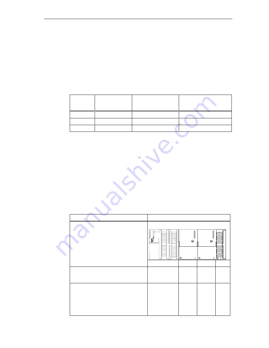
Differences in the case of MPI addresses of CPs/FMs in an S7-300

Table 4-13

MPI addresses of CPs/FMs in an S7-300

Options

Example:

CPU

CP

SF

BUSF

DC5V

FRCE

RUN

STOP

CP

Example:

An S7-300 CPU and 2 CPs in one unit.

You have two options for assigning MPI
addresses of CPs/FMs installed in one
unit:

CPU

CP

CP

First option: The CPU adopts the CP
MPI addresses you specify in STEP 7.

MPI address

MPI
address
+x

MPI
address.
+y

Second option: The CPU automatically
determines the CP MPI addresses in your
configuration according to the following
pattern: MPI address CPU; MPI address
+1; MPI a2.

(Default)

MPI address

MPI
address
+1

MPI
address
+2

Summary of Contents for Simatic S7-300

Page 1: ... Commissioning 8 Maintenance 9 Testing functions Diagnostics and Fault Elimination 10 Appendix 11 Glossary 12 Index SIMATIC S7 300 Programmable Controller Hardware and Installation Manual This manual is part of the documentation package with order number 6ES7398 8FA10 8BA0 Edition 10 2001 A5E00105492 01 ...

Page 2: ... if proper precautions are not taken Warning indicates that death severe personal injury or substantial property damage can result if proper precautions are not taken Caution indicates that minor personal injury can result if proper precautions are not taken Caution indicates that property damage can result if proper precautions are not taken Note draws your attention to particularly important inf...

Page 3: ...sembly protective measures and grounding 4 14 4 8 1 Grounding conception and overall structure 4 14 4 8 2 S7 300 installation with grounded reference potential 4 15 4 8 3 S7 300 assembly with floating reference potential not CPU 312 IFM and CPU 31xC 4 16 4 8 4 Isolated or non isolated modules 4 18 4 8 5 Grounding 4 21 4 8 6 Overview Grounding 4 23 4 9 Selecting the load power supply unit 4 26 4 10...

Page 4: ... data 7 10 8 8Commissioning 8 1 8 1 In this Chapter 8 1 8 2 Commissioning procedure 8 1 8 3 The commissioning checklist 8 4 8 4 Insert the backup battery or rechargeable battery 8 6 8 5 Inserting or replacing a Memory Card or Micro Memory Card 8 7 8 6 Commissioning modules 8 9 8 6 1 Connecting the PG 8 9 8 6 2 Initial power on 8 13 8 6 3 Resetting CPU memory 8 13 8 6 4 Starting SIMATIC Manager 8 1...

Page 5: ... 11 3 11 2 1 Basic points for system installations conforming with EMC requirements 11 3 11 2 2 Five basic rules for insuring EMC 11 6 11 2 3 EMC compatible installation of PLC 11 7 11 2 4 Examples of an EMC compatible installation 11 8 11 2 5 Shielding of cables 11 12 11 2 6 Equipotential bonding 11 13 11 2 7 Cable routing inside buildings 11 14 11 2 8 Outdoor cable routing 11 17 11 3 Lightning a...

Page 6: ... 2 m profile rail 5 4 5 2 Free space required for an S7 300 installation 5 6 5 3 Inserting slot numbers in modules 5 10 6 1 Bonding the protective conductor to the profile rail 6 4 6 2 Setting the mains voltage selector switch for the PS 307 6 5 6 3 Wiring the power supply module and the CPU 6 7 6 4 Move the front connector into wiring position 6 9 6 5 Slide the labelled strips into the front pane...

Page 7: ...c address for the receiving station with direct data exchange 10 15 10 6 Diagnostic addresses for DP masters and DP slaves 10 19 10 7 Structure of slave diagnostic data 10 22 10 8 Structure of module diagnostics of CPU 31x 2 10 25 10 9 Structure of the module status 10 26 10 10 Structure of the interrupt status for CPU 31xC 10 27 10 11 Byte y 4 to y 7 for Diagnostic Process interrupts 10 28 11 1 P...

Page 8: ...load power supplies 4 26 4 11 Subnet nodes 4 30 4 12 MPI PROFIBUS DP addresses 4 31 4 13 MPI addresses of CPs FMs in an S7 300 4 31 4 14 Connectable Devices 4 34 4 15 Available bus cables 4 34 4 16 Properties of PROFIBUS cables 4 35 4 17 Marginal conditions for wiring interior bus cables 4 35 4 18 Bus connectors 4 36 4 19 RS485 Repeater 4 36 4 20 PG patch cord 4 37 4 21 Permissible cable lengths i...

Page 9: ...0 10 10 5 The BUSF BUSF1 and BUSF2 LEDs 10 11 10 6 BUSF LED is lit 10 11 10 7 BUSF LED flashes 10 11 10 8 Event recognition of CPU 31x 2 operating as DP master 10 13 10 9 Evaluating RUN to STOP transitions of the DP slave in the DP master 10 14 10 10 Reading out diagnostic data in the master system using STEP 5 and STEP 7 10 16 10 11 Event recognition of CPUs 31x 2 operating as DP slave 10 20 10 1...

Page 10: ...Contents S7 300 Programmable Controller Hardware and Installation x A5E00105492 01 ...

Page 11: ... CPU Data Reference Manual Approvals The product series SIMATIC S7 300 is approved by Underwriters Laboratories Inc UL 508 Industrial Control Equipment Canadian Standards Association CSA C22 2 No 142 Process Control Equipment Factory Mutual Research Approval Standard Class Number 3611 CE Label Series SIMATIC S7 300 products are compliant with the following EC Guidelines and safety requirements EC ...

Page 12: ...nical specifications of the CPU Reference manua module data Manual Function description and technical specifications for the signal modules power supply modules and the interface modules Operating list CPU 312 IFM 314 IFM 313 315 315 2 DP 316 2 DP 318 2 DP CPUs 312 C bis 314C 2 PtP DP List of stored intructions of the CPUs and their execution times List of executable blocks OBs SFCs SFBs and their...

Page 13: ...upport Please contact your Siemens partner at your local Siemens office if you have any queries about the products described in this manual http www ad siemens de partner Training Center We offer corresponding S7 300 PLC courses that can help you to get started Please contact your local Training Center or the Central Training Center in Nuremberg D 90327 Germany Phone 499 911 895 3200 http www sitr...

Page 14: ... Fax 49 911 895 7001 GMT 1 00 Europe Africa Nuremberg Authorization Local time Mo Fr 7 00 to 17 00 Phone 49 911 895 7200 Fax 49 911 895 7201 E mail authorization nbgm siemens de GMT 1 00 America Johnson City Technical Support and Authorization Local time Mo Fr 8 00 to 19 00 Phone 1 423 262 2522 Fax 1 423 262 2289 E mail simatic hotline sea siemens com GMT 5 00 Asia Australia Singapore Technical Su...

Page 15: ...ormation What s new FAQs Frequently Asked Questions Downloads Tips and Tricks Our newsletter always provides you with the latest information on your products The Knowledge Manager finds the documents you require Users and specialists all over the world share their experience in our Forum You can find your local service partner for Automation Drives in our Partner Database Information relating to o...

Page 16: ...Preface S7 300 Programmable Controller Hardware and Installation 1 6 A5E00105492 01 ...

Page 17: ...ro PLC Fast high performance and versatile Compact PLC CPUs 31xC with integrated functionality Fast high performance rugged and versatile Power PLC with high performance communication capabilities Compact and compatible Complete PLC Available Documentation Selection and Configuration Table 2 2 Ambient influence on the PLC Information on is available in What provisions do I have to make for PLC ins...

Page 18: ...e module for CPU Reference Manual CPU Data for signal modules Reference Manual Module Data How do I wire the sensors actuators to the PLC using front connectors Chapter Wiring Wiring front connectors in the Installation Manual When do I require expansion modules EG and how are they connected Chapter Configuring optional expansions and networking in the Installation Manual How do I mount modules on...

Page 19: ...ation with the help of communication processors CPs the respective device Manual Which communication network is most suitable for my application Chapter Configuring Configuring subnets in the Installation Manual Manual Communication with SIMATIC How do I network the specific modules Chapter Configuring and wiring in the Installation Manual Table 2 9 Software Information on is available in Which so...

Page 20: ...successfully install a SIMATIC S7 system Install an S7 system as follows Configuration Installation Wiring Address Installation completed continue with commissioning Yes No Should a subnet be created Network Figure 2 1 Installing a SIMATIC S7 system Basic rules In view of the many and versatile applications of an S7 system this chapter can only cover the basics on its electrical configuration You ...

Page 21: ...above if you want to change an existing system configuration When retrofitting signal modules also proceed in a configuring mounting wiring etc sequence In this case however you only have to consider information that is relevant to the new module Cross reference Also note the description of specific module in the manual SIMATIC S7 300 PLCs Module Data Reference Manual ...

Page 22: ...Quick Guide S7 300 Programmable Controller Hardware and Installation 2 6 A5E00105492 01 ...

Page 23: ...n An S7 300 consists of the following modules Power supply PS CPU Signal modules SM Function modules FM Communication processors CP Multiple S7 300 CPUs can communicate with each other and with SIMATIC S7 PLCs across PROFIBUS cable You require a programming device PG to program the S7 300 PLC Interconnect the PG and the CPU with a PG cable The figure below shows you a possible configuration consis...

Page 24: ...IBUS Bus cable PG cable 1 2 3 4 5 4 5 1 2 3 SF BUSF DC5V FRCE RUN STOP SIEMENS 1 2 3 SF BUSF DC5V FRCE RUN STOP SIEMENS Figure 3 1 S7 300 modules S7 300 PLCs can be installed horizontally or vertically The following ambient air temperatures are permissible horizontal installation from 0 C to 60 C vertical installation from 0 C to 40 C ...

Page 25: ...SIEMENS PS CPU Figure 3 2 Horizontal and vertical installation of an S7 300 S7 300 modules You can choose from a number of modules to install and commission an S7 300 PLCs The table below shows the major modules and their function Table 3 1 S7 300 modules Components Function Illustration Profile rail Accessory Shielding element is the module rack for an S7 300 Power supply PS converts mains voltag...

Page 26: ...s digital I O modules analog input modules analog output modules analog I O modules Accessory Front connectors adapt different process signal levels to the S7 300 Function modules FM Accessory Front connectors for time critical process signal processing tasks with high memory load e g positioning or controlling Communication processor CP Accessory Connecting cable relieves the CPU of communication...

Page 27: ...nction Illustration PG cable interconnects CPU and PG PC RS485 Repeater for the amplification of signals in an MPI or PROFIBUS subnet and for interconnecting segments of an MPI or PROFIBUS subnet Programming device PG or PC with the STEP 7 software package for configuring programming and testing the S7 300 ...

Page 28: ...Product overview S7 300 Programmable Controller Hardware and Installation 3 6 A5E00105492 01 ...

Page 29: ...ing for SIMATIC professionals as well as the basics for newcomers In the appendix you can find Information on ambient conditions Appendix Ambient Conditions Information on special protective measures Appendix Electrical protective measures e g protection against inductive surge voltage lightning etc 4 2 Basics Warning Open components S7 300 modules are open components That means you must always in...

Page 30: ...one or multiple expansion devices EDs The module rack containing the CPU is referred to as the central unit CU Module racks equipped with modules form the expansion devices EDs connected to the system s CU When should I use expansion devices You can use EDs if the number of CU slots is insufficient for your application When using EDs you might require further power supply modules in addition to th...

Page 31: ...EMENS PS CPU Rack rails Figure 4 1 Horizontal and vertical installation Further information on the selection and dimensions of profile rails module racks is found in Chapter Module dimensions connections and interfaces IMs are found in Chapter Arranging modules on multiple module racks the most important rules on S7 300 operation are found in the Appendix General rules and regulations on S7 300 op...

Page 32: ... 80 mm Power supply PS 307 10 A 200 mm CPU 312C 312 IFM 313 314 315 315 2 DP 316 2 DP 80 mm CPU 313C 313C 2 DP 313C 2 PtP 314C 314C 2 DP 314C 2 PtP 120 mm CPU 314 IFM 318 2 DP 160 mm Analog I O modules 40 mm Digital I O modules 40 mm Simulator module SM 374 40 mm Interface modules IM 360 and IM 365 40 mm Interface module IM 361 80 mm Module height 125 mm Module height with shielding terminal modul...

Page 33: ...terminal module max 4 Table 4 3 Shielding terminals Overview Cable with shielding diameter Shielding terminal Order No Cable shielding diameter 2 mm to 6 mm 6ES7 390 5AB00 0AA0 Cable shielding diameter 3 mm to 8 mm 6ES7 390 5BA00 0AA0 Cable shielding diameter 4 mm to 13 mm 6ES7 390 5CA00 0AA0 1 2 2 Shield must be under shield terminal clamp Figure 4 2 Shielding terminal module ...

Page 34: ...llation space and to ensure elimination of heat generated by the modules The S7 300 assembly on multiple module racks shown in the figure below specifies the clearance between module racks and adjacent components cable ducts cabinet walls etc 40 mm 20 mm 40 mm a 200 mm a CPU CPU 40 mm when using a shield contact element from its lower edge 40 mm 20 mm e g cable channel Figure 4 3 Clearance ...

Page 35: ...y module to the right side of the CPU Order No 6ES7 370 0AA01 0AA0 This gives you the option of inserting a second module rack for your application in the future simply by replacing the dummy module with an interface module and without having to reinstall and rewire the first module rack Rules Arranging modules on a single module rack The following rules apply to single rack module installations N...

Page 36: ...rdware and Installation 4 8 A5E00105492 01 Example The figure below shows the arrangement of eight signal modules in an S7 300 assembly PS CPU SMs 1 2 3 4 5 6 7 8 SF BUSF DC5V FRCE RUN STOP SIEMENS Figure 4 4 Module rack with eight signal modules ...

Page 37: ...ximum number of expansion devices 3 1 Length of the connecting cables 1 m 6ES7 368 3BB01 0AA0 2 5 m 6ES7 368 3BC51 0AA0 5 m 6ES7 368 3BF01 0AA0 10 m 6ES7 368 3CB01 0AA0 1 m hardwired Remarks Module rack 1 can only receive signal modules total current load is limited to 1 2 A whereby the maximum for module rack 1 is 0 8 A These restrictions do not apply for operation with interface modules IM 360 I...

Page 38: ...dule racks are interconnected with low impedance the module racks of a grounded assembly are grounded in a star pattern the contact springs of the module racks are clean and not bent in order to ensure interference current diversion Example of a full assembly The figure shows the arrangement of modules in an S7 300 assembly on 4 module racks PS CPU SMs IM Connecting cable 368 Rack 0 ZG Rack 1 EG R...

Page 39: ...tal power loss of all components in the cabinet The ambient conditions temperature humidity dust chemical influence explosion hazard at the cabinet s place of installation determine the degree of protection IP xx required for the cabinet Further information on degree of protection is found in IEC 529 and DIN 40050 Important cabinet types The table below gives you an overview of the commonly used c...

Page 40: ...protection IP 54 Degree of protection IP 54 Typical power dissipation under following marginal conditions Cabinet size 600 mm x 600 mm x 2 200 mm Difference between the outer and inner temperature of the cabinet is 20 C for other temperature differences refer to the temperature charts of the cabinet manufacturer up to 700 W up to 2 700 W with fine filter up to 1 400 W up to 260 W up to 360 W up to...

Page 41: ...it 200 W under full load This results in a total power loss of 650 W Power loss dissipated The diagram in the figure below shows guide values for the permissible ambient air temperature of a cabinet with the dimensions 600 mm x 600 mm x 2 000 mm depending on power loss these values only apply if you maintain the specified installation and clearance dimensions for module racks profile rails 200 400...

Page 42: ...all structure of an S7 300 operated on a grounded power supply TN S network The following aspects are covered Circuit breaking devices short circuit and overload protection to VDE 0100 and VDE 0113 Load power supplies and load circuits Grounding conception In view of the many and versatile S7 300 applications this chapter can only describe the basic rules on its electrical configuration You must o...

Page 43: ...tion by transformer mandatory 1 This column refers to the indexes of the figure in the Chapter Overview Grounding Further information on protective measures e g EMC lightning protection is found in the Appendix 4 8 2 S7 300 installation with grounded reference potential Introduction In an S7 300 configuration with grounded reference potential occurring interference current is dissipated to the gro...

Page 44: ...300 installation with floating reference potential occurring interference current is dissipated to the ground conductor to ground via an RC combination integrated in the CPU A configuration with grounded reference potential is possible with following CPUs CPU 313 314 314 IFM 315 315 2 DP 316 2 DP 318 2 DP Application In larger plants it might be required to install the S7 300 with floating referen...

Page 45: ...ve the jumper on the CPU between the M terminal and functional ground If the jumper is not installed the reference potential of the S7 300 is connected internally to the protective conductor over an RC network and the profile rail This discharges radio frequency interference current and avoids static charge M L M 47 nF 1 MW M Ground bus Figure 4 8 S7 300 configuration with floating reference poten...

Page 46: ...circuits with separate reference potential Examples DC load circuits whose sensors have different reference potentials for example if grounded sensors are located at some considerable distance from the control system and no equipotential bonding is possible DC load circuits with grounded positive pole L battery circuits Isolated modules and grounding conception You can use isolated modules regardl...

Page 47: ...omatically established Figure 4 9 Configuration with isolated modules Non isolated modules In configurations with non isolated modules the reference potentials of the control circuit Minternal and load circuit Mexternal are not electrically isolated see the figure below Example For operation with an SM 334 AI 4 AO 2 analog I O module you must connect one of the grounding terminals Manalog to the C...

Page 48: ...re and Installation 4 20 A5E00105492 01 L N M L1 L M PS S7 300 CPU µ P L1 N U Internal M internal Data 4AI 2AO PE 1mm 2 Manalog M external V A D A A D Ground bus in cabinet DC 24 V load power supply Figure 4 10 Configuration with non isolated modules ...

Page 49: ...er is protected from electrical shock It also deflects interference which is emitted from external power supply cables and signal cables to cables connected to I O devices Measures for protective grounding The table below shows an overview of the most important measures for protective grounding Table 4 8 Measures for protective grounding Device Measures Cabinet mounting structure Connection to cen...

Page 50: ...r if foil shielding is used static shielding Note Potential differences between two grounding points might cause an equipotential current flow across shielding connected at both ends In this case you should install an additional equipotential conductor Caution Always avoid the flow of operating current to ground Details on cable shielding and equipotential bonding are found in the Appendix under t...

Page 51: ...s Remarks grounded Connect Mexternal with M on the CPU Connect or do not connect Mexternal to the common grounding line ungrounded Connect Mexternal with M on the CPU Connect or do not connect Mexternal to the common grounding line ungrounded operation of CPU31xC and 312 IFM is not possible 4 8 6 Overview Grounding CPU 31xC The figure below shows you the complete assembly of an S7 300 with CPU 31x...

Page 52: ... in cabinet PS CPU SM Signal modules L1 N L M µP AC 24 to 230V l for AC modules oad circuit DC 5 to 60V l for non isolated DC modules oad circuit DC 5 to 60V load circuit for isolated DC modules AC AC AC AC DC DC L1 L2 L3 N PE In the case of CPU 31xC or 312 IFM the connection will automatically be established Figure 4 11 Grounding conception S7 300 with CPU 31xC ...

Page 53: ...r the 24 VDC modules Note The arrangement displayed does not correspond with the physical arrangement it was merely selected to give you a clear overview low voltage distribution e g TN S System 3 x 400 V cabinet Rail Ground bus in cabinet PS CPU SM Signal modules L1 N L M µP AC 24 to 230V load circuit for AC modules DC 5 to 60V load circuit for non isolated DC modules DC 5 to 60V isolated for DC ...

Page 54: ...load circuits Requirements The DC load power supply must meet following requirements It must provide an extra low voltage of 60 VDC and be safely isolated from mains Safe isolation from mains can be realized for example in accordance with VDE 0100 Part 410 HD 384 4 41 IEC 364 4 41 as functional extra low voltage with safe isolation or VDE 0805 EN 60950 IEC 950 as safety extra low voltage SELV or V...

Page 55: ...y Apart from powering the CPU the PS 307 also supplies the load current for the 24 VDC modules Note The arrangement displayed does not correspond with the physical arrangement it was merely selected to give you a clear overview N M L1 M PS S7 300 CPU µP L1 L2 L3 N PE SM Rail Low voltage distribution e g TN S System 3 x 400 V Ground bus in cabinet load circuit DC 24 V for DC modules L signal module...

Page 56: ...e node number and highest MPI address even after memory reset voltage failure or deletion of the CPU parameter configuration PROFIBUS PROFIBUS in the open multivendor communication system of SIMATIC represents the network on cell and field level PROFIBUS is available in two versions 1 PROFIBUS DP fieldbus for fast cyclic data exchange and PROFIBUS PA for the intrinsically safe area 2 The cell leve...

Page 57: ...sors Actuator Sensor Interface ASI The ASI or actuator sensor interface represents a subnet system on the lowest process level for automation systems It is used especially for networking digital sensors and actuators The maximum data volume is 4 bit per slave station With S7 300 CPUs you can connect to an ASI only with the help of communication processors Same configuration for MPI and PROFIBUS DP...

Page 58: ...ssion rates are possible MPI 12 Mbps with CPU 318 2 DP 187 5 Kbps with all other CPUs PROFIBUS DP 12 Mbps PtP Half duplex 38 4 Kbps Full duplex 19 2 Kbps Number of nodes Maximum possible number of nodes per subnet Table 4 11 Subnet nodes Parameter MPI PROFIBUS DP PtP Number 127 126 1 2 Addresses 0 to 126 0 to 125 Remarks Default 32 addresses Reserved are address 0 for PG address 1 for OP of those ...

Page 59: ...g MPI PROFIBUS addresses All MPI PROFIBUS addresses in a subnet must be unique The highest MPI PROFIBUS address must be of the physical MPI PROFIBUS address and it must be identical for each node Exception Connecting a PG to multiple nodes refer to the next Chapter Differences in the case of MPI addresses of CPs FMs in an S7 300 Table 4 13 MPI addresses of CPs FMs in an S7 300 Options Example CPU ...

Page 60: ...r a service PG that you can subsequently connect briefly to the PROFIBUS subnet if required Therefore assign unique PROFIBUS addresses to PGs integrated in the PROFIBUS subnet PROFIBUS DP Electrical conductor or optical waveguide Use optical waveguides instead of copper conductors if you want your fieldbus to cover greater distances regardless of the transmission rate and be insensitive to externa...

Page 61: ...ts its bus parameter configuration e g transmission rate via PROFIBUS DP interface This means that a programming device for example can automatically hook up to a PROFIBUS DP subnet In your configuration you can specify to disable bus parameter broadcasting CPUs 313C 2 DP and 314C 2 DP are equipped with a second interface an RS485 PROFIBUS DP interface that you can configure as master or slave PtP...

Page 62: ...n PtP communication are also found in the Technological Functions manual 4 10 4 Network components PROFIBUS bus cable For PROFIBUS DP or MPI networking we offer you the following bus cables for diverse fields of application Table 4 15 Available bus cables Bus cable Order No PROFIBUS cable 6XV1 830 0AH10 PROFIBUS cable halogen free 6XV1 830 0CH10 PROFIBUS underground cable 6XV1 830 3AH10 PROFIBUS t...

Page 63: ... Wiring bus cables When wiring PROFIBUS cables you must not twist stretch or compress them When wiring indoor bus cables also maintain the following marginal conditions dA outer cable diameter Table 4 17 Marginal conditions for wiring interior bus cables Characteristics Condition Bending radius one off 80 mm 10 x dA Bending radius multiple times 160 mm 20 x dA Permissible temperature range during ...

Page 64: ...with PG interface 6ES7 972 0BA40 0XA0 6ES7 972 0BB40 0XA0 Application You require these bus connectors to connect the PROFIBUS cable the an MPI or PROFIBUS DP interface You do not require a bus connector for DP slaves with degree of protection IP 65 e g ET 200C RS485 Repeater RS485 Repeater Table 4 19 RS485 Repeater Type Order No RS485 Repeater 6ES7 972 0AA00 0XA0 Purpose An RS485 repeater amplifi...

Page 65: ...odes in your subnet even if it is not assigned its own MPI PROFIBUS address Technical data and installation instructions are found in the RS485 Repeater product information PG patch cord Table 4 20 PG patch cord Type Order No PG patch cord 6ES7 901 4BD00 0XA0 Stub cables If you do not want to install the bus cable directly in the bus connector for example when using an L2 bus terminal you must tak...

Page 66: ...egment in the PROFIBUS Subnet The cable length in a segment of a PROFIBUS subnet depends on the transmission rate Table 4 22 Permissible cable lengths in an MPI subnet segment Transmission rate Maximum cable length in a segment 9 6 Kbps to 187 5 Kbps 1 000 m 500 Kbps M 400 1 5 Mbps M 200 3 Mbps to 12 Mbps M 100 Longer cable lengths If you want to implement cable lengths above those permitted in a ...

Page 67: ...with stub cable length of Transmission rate Max length of stub cables per segment 1 5 m or 1 6 m 3 m 9 6 Kbps to 93 75 Kbps 96 m 32 32 187 5 Kbps 75 m 32 25 500 Kbps 30 m 20 10 1 5 Mbps 10 m 6 3 3 Mbps to 12 Mbps 1 1 1 1 To connect PGs or PCs when operating above 3 Mbps use patch cords with the Order No 6ES7 901 4BD00 0XA0 In your bus assembly you can use multiple PG patch cords with this order no...

Page 68: ...I address address 7 here In the case of the CPU 318 2 DP the FMs CPs do not have their own MPI address In the case of the S7 300 CPUs without CPU 318 2 DP you can also allocate MPI addresses as you wish MPI addresses of nodes Terminating resistance on S7 300 3 SF BUSF BUSF DC5V FRCE RUN STOP SIEMENS S7 300 11 SF BUSF DC5V FRCE RUN STOP SIEMENS S7 300 2 SF BUSF DC5V FRCE RUN STOP SIEMENS S7 300 4 S...

Page 69: ...ers max 50 m max 50 m Terminating resistance on S7 300 spur line PG connected via spur line for maintenance purposes 0 0 x MPI addresses of nodes 7 3 4 9 OP 27 PG PG OP 27 RS 485 Repeater RS 485 Repeater max 1000 m 11 OP 27 S7 300 6 SF BUSF DC5V FRCE RUN STOP SIEMENS S7 300 10 SF BUSF DC5V FRCE RUN STOP SIEMENS S7 300 5 SF BUSF DC5V FRCE RUN STOP SIEMENS SF BUSF DC5V FRCE RUN STOP SIEMENS S7 300 8...

Page 70: ...ning Maintenance with MPI address 0 0 x PROFIBUS addresses of nodes S7 300 with CPU 31x 2 DP as DP master ET 200M 11 7 8 9 10 2 3 4 5 6 S5 95U ET 200B ET 200B À À Terminating resistance on ET 200M ET 200M ET 200M ET 200B ET 200B 2 Default PROFIBUS address for DP master 0 À PG 3 0 x MPI addresses of nodes SF BUSF DC5V DC5V FRCE RUN STOP SIEMENS SF BUSF DC5V FRCE RUN STOP SIEMENS S7 300 12 Figure 4 ...

Page 71: ... S5 95U ET 200B ET 200B 2 3 4 5 6 8 7 ET 200M 2 3 4 5 6 8 7 11 9 0 PROFIBUS subnet MPI subnet S7 300 with CPU 314C 2 DP as DP master Terminating resistance on Connect via spur lines for commisioning maintenance with default MPI address only 0 x MPI addresses of nodes 0 x PROFIBUS addresses of nodes RS 485 Repeater SF BUSF DC5V FRCE RUN STOP SIEMENS SF BUSF DC5V FRCE RUN STOP SIEMENS SF BUSF DC5V F...

Page 72: ...r all stations and downloaded the configuration to every module capable of routing This also applies to all changes made in the network Thus every router knows all possible paths to a target station MPI network1 PG PC 1 ET 200 S7 400 with CPU 416 PG PC 2 PG PC 3 S7 400 with CPU 417 S7 300 with CPU 31xC 2 DP PROFIBUS DP network MPI network 2 SF BUSF DC5V FRCE RUN STOP SIEMENS SF BUSF DC5V FRCE RUN ...

Page 73: ...SF BUSF DC5V FRCE RUN STOP SIEMENS S7 300 SF BUSF DC5V FRCE FRCE RUN STOP SIEMENS Figure 4 19 Activation of the terminating resistors in an MPI subnet Warning Disturbance of data traffic might occur on the bus A bus segment must always be terminated at both ends with the terminating resistor This for example is not the case if the last slave with bus connector is off power Since the bus connector ...

Page 74: ...Configuring S7 300 Programmable Controller Hardware and Installation 4 46 A5E00105492 01 ...

Page 75: ...31 2 and EC Guideline 73 23 EEC Low Voltage Guideline and to UL CSA Approval an open type In order to conform with specifications on safe operation relating to mechanical strength inflammability stability and touch protection the following alternative installation modes are prescribed Installation in a suitable cubicle Installation in a suitable cabinet Installation in an appropriately equipped an...

Page 76: ...M 314 IFM and 31xC Tip Templates for labeling strips can be obtained from the internet at http www ad siemens de cs info under article ID 406745 1 bus connector For electrical interconnection of modules Signal module SM Function Module FM 1 labeling strip for labeling module I Os Tip Templates for labeling strips can be obtained from the internet at http www ad siemens de cs info under article ID ...

Page 77: ...ing the profile rail wrench or screwdriver matching the selected fixing screws diverse M6 screws length depends on the place of installation with nuts and spring lock washers screw fastening the modules on the profile rail screwdriver with 3 5 mm blade width cylindrical design 5 2 Installing the profile rail Introduction Profile rails are available in two versions Ready to use in four standard len...

Page 78: ...eds 830 mm you must stabilize it by providing additional holes for fixing it with more screws Mark out these holes along the groove in the middle section of the profile rail see the Figure below The pitch should be approx 500 mm 4 Drill the marked holes to a diameter of 6 5 0 2 mm for M6 screws 5 Mount an M6 bolt for fixing the ground conductor Groove for drilling extra fixing screw Hole for conne...

Page 79: ...ns for the profile rail are shown in the table below Table 5 3 Mounting holes for profile rails Standard profile rail 2 m profile rail 32 5 mm 57 2 mm a b 32 5 mm 57 2 mm 15 mm ca 500 mm ca 500 mm 15 mm _ _ _ _ 32 5 mm 57 2 mm Length of rail Dimension a Dimension b 160 mm 10 mm 140 mm 482 6 mm 8 3 mm 466 mm 530 mm 15 mm 500 mm 830 mm 15 mm 800 mm ...

Page 80: ...washers to ISO 7092 DIN 433 Mounting the profile rail 1 When you mount the profile rails allow sufficient space for mounting modules and heat elimination at least 40 mm above and below the modules See the figure below 2 Mark up the mounting holes on the mounting surface Drill the holes to a diameter of 6 5 0 2 mm 3 Screw on the profile rail M6 screws Note Take care to create a low impedance connec...

Page 81: ...nap the modules onto the profile rail starting at the left and in the following order 1 Power supply module 2 CPU 3 signal modules function modules communication modules interface modules Note If you install SM 331 analog input modules please check before installation whether you have to reposition the measuring range submodules at the side of the module See Chapter 4 on analog modules in the Modu...

Page 82: ...the other modules The last module is not equipped with a bus connector 2 Suspend all modules in their specified sequence onto the rail 1 slide them up to the module on the left 2 then swing them down 3 1 3 2 3 Screw fasten all modules tightening the screws with a torque of 0 8 N m to 1 1 N m 0 8 1 1 Nm CPU Inserting the key After you have mounted all modules insert the key into the S7 300 CPU s mo...

Page 83: ...bers for S7 modules Slot number Module Remarks 1 Power supply PS 2 CPU 3 Interface module IM To the right of the CPU 4 1st signal module To the right of the CPU or IM 5 2nd signal module 6 3rd signal module 7 4th signal module 8 5th signal module 9 6th signal module 10 7th signal module 11 8th signal module ...

Page 84: ...sponding slot number in front of the respective module 2 Insert the pin into the opening on the module 1 3 Press the slot number into the module 2 The slot number breaks off from the wheel The figure below illustrates this procedure The slot number labels are included with the CPU 1 2 Figure 5 3 Inserting slot numbers in modules ...

Page 85: ...ccessories listed in the table below Table 6 1 Wiring accessories Accessories Description Connection comb included with the PS for the connection between the power supply module and the CPU not CPU 31xC Front connector for the connection of system sensors actuators to the S7 300 Labeling strips for labeling the module I Os Shielding element shielding terminals matching the shielding diameter for c...

Page 86: ...rules to DIN 46228 Wiring the front connector Screwdriver with a blade width of 3 5 mm side cutter wire stripping tool Flexible cable 0 25 mm 2 to 0 75 1 5 mm 2 If required shielded cables If required wire end ferrules to DIN 46228 Brief overview of the power supply module and CPU Table 6 3 Conditions for wiring the PS and CPU Connectable cables to PS and CPU solid conductors No flexible conductor...

Page 87: ...ply 1 5 mm 2 Number of conductors per terminal 1 conductor or 2 conductors up to 1 5 mm2 total in a common wire end ferrule 1 conductor or 2 conductors up to 0 75 mm 2 total in a common wire end ferrule Diameter of the conductor insulation max 3 1 mm max 2 0 mm for 40 conductors max 3 1 mm for 20 conductors Stripped length 6 mm 6 mm Wire end ferrules to DIN 46228 Without insulating collar With ins...

Page 88: ...ctive conductor bolt Minimum cross section of the protective conductor 10 mm 2 The figure below shows how the protective conductor must be bonded to the profile rail Figure 6 1 Bonding the protective conductor to the profile rail Note Always ensure a low impedance connection of the protective conductor You can achieve this by bonding a cable with low impedance and as short as possible to a large c...

Page 89: ...actory setting for PS 307 is always 230 VAC Setting the mains voltage selector switch Check to see whether the selector switch is set to the correct mains voltage You can change the selector switch setting as follows 1 Remove the protective cap with the help of a screwdriver 1 2 Set the selector switch to your mains voltage 2 3 Replace the cover 1 2 Figure 6 2 Setting the mains voltage selector sw...

Page 90: ...upply module and any additional load power supplies are switched on Always wire the S7 300 with the power turned off 1 Open the front panel to the PS 307 power supply module and CPU 2 Open the strain relief clamp on the PS 307 3 Strip the power cable to a length of 11 mm and connect it to L1 N and to the ground conductor terminal of the PS 307 4 Screw tighten the strain relief clamp again 5 You ha...

Page 91: ...31xC removable connecting cables for the CPU s power supply Other CPU s besides CPU 312 IFM strain relief assembly power connector 230 V 120 V 0 5 to 0 8 Nm CPU 312 IFM wire L and M via the front connector of CPU 312 IFM Figure 6 3 Wiring the power supply module and the CPU Note The PS 307 power supply module is equipped with two additional DC 24 V connections L and M for the supply of I O modules...

Page 92: ...igning front connectors to modules Module Front connectors with screw terminals Order No Front connectors with spring terminals Order No Signal modules not 32 channel Function modules Communication module CP 342 2 CPU 312 IFM 6ES7 392 1AJ00 0AA0 6ES7 392 1BJ00 0AA0 Signal modules 32 channel CPUs 314 IFM and 31xC 6ES7 392 1AM00 0AA0 6ES7 392 1BM01 0AA0 Termination with spring terminals To terminate...

Page 93: ...rned off 1 Open the front panel 1 2 Move the front connector into wiring position 2 Slide the front connector into the signal module until it latches The front connector still protrudes from the module in this position Advantage of the wiring position Easy wiring In this wiring position the front connector does not contact the module 3 Strip the leads to a length of 6 mm 4 Crimp on the cable end s...

Page 94: ...ing passes from terminals 39 19 38 18 etc until you have reached terminals 21 and 1 2 If not Starting at terminal 1 work your way up to terminal 20 Starting at terminal 1 or 21 wire the connector working in alternating passes from terminals 2 22 3 23 etc until you have reached terminals 20 and 40 3 Front connectors with screw terminals Screw tighten unused terminals also 4 Attach the cable strain ...

Page 95: ...ule 1 Hold the unlocking mechanism in this position and insert the front connector into the module 1a Provided the front connector is seated correctly in the module the unlocking mechanism automatically returns to initial position when you release it Screw tighten the fixing screw in the center of the connector 1 This pulls the front connector completely into contact with the module 1 Note When yo...

Page 96: ...s to modules Module Labeling strip Order No Signal modules not 32 channel Function modules Communication module CP 342 2 6ES7 392 2XX00 0AA0 Signal modules 32 channel 6ES7 392 2XX10 0AA0 Labeling and inserting labeling strips 1 Label the strips with the addresses of the sensors actuators 2 Slide the labelled strips into the front panel Figure 6 5 Slide the labelled strips into the front panel Tip ...

Page 97: ...g terminal Order No 2 cables each one with a shielding diameter of 2 to 6 mm 6ES7 390 5AB00 0AA0 1 cable with a shielding diameter of 3 to 8 mm 6ES7 390 5BA00 0AA0 1 cable with a shielding diameter of 4 to 13 mm 6ES7 390 5CA00 0AA0 The shielding contact element width is 80 mm It provides termination space in two rows each one for 4 shielding terminals Mounting the shielding contact element 1 Push ...

Page 98: ...rminated per shielding terminal see the figure below The cable is clamped in at the stripped cable shielding 1 Strip the cable shielding to a length of at least 20 mm 2 Clamp in the stripped cable shielding underneath the shielding contact clamp Push the shielding clamp towards the module 1 and feed the cable through underneath the clamp 2 If you need more than four shielding terminals start wirin...

Page 99: ...eld terminal clamp Figure 6 7 Connecting 2 wire cables to the shielding contact element Tip For your connection to the front connector leave a sufficient cable length behind the shielding terminal This allows you to disconnect the front connector e g for repairs without having to open the shielding contact element ...

Page 100: ...ires to the same terminal e g always wire green to terminal A and red to terminal B 4 Press the cable sheath into the clamp Take care that the bare shielding contacts the shielding contact surface 5 Screw tighten the wire terminals 6 Close the bus connector housing Fast Connect bus connector 1 Strip the bus cable Details on stripped lengths are found in the product information included with the bu...

Page 101: ...terminating resistor is active Terminating resistance switched on Terminating resistance switched off on off On Off on off On Off Figure 6 8 Bus connector Enabled and disabled terminating resistor Removing bus connectors With a looped through bus cable you can unplug the bus connector from the PROFIBUS DP interface at any time without interrupting data communication on the network Possible data tr...

Page 102: ...Wiring S7 300 Programmable Controller Hardware and Installation 6 18 A5E00105492 01 ...

Page 103: ...addressing of modules Introduction In slot based addressing default addressing a module start address is allocated to each slot number This is a digital or analog address depending on the type of module This section shows you which module start address is assigned to which slot number You need this information to determine the start addresses of the installed modules Maximum assembly and the corre...

Page 104: ...72 7 7 7 44 76 108 432 560 688 8 8 8 48 80 112 448 576 704 9 9 9 52 84 116 464 592 720 10 10 10 56 88 120 480 608 736 11 11 11 60 92 124 496 624 752 slot number slot number slot number BG digital initial address BG digital initial address BG initial address digital BG analog initial address BG analog initial address BG Anfangsadresse analog not with CPU 314 IFM CPU 31xC 124 CPU 31xC 752 CPU 31xC s...

Page 105: ...program addresses which are independent of the respective S7 300 configuration 7 4 Addressing signal modules Introduction This section shows you how to address signal modules You need this information in order to be able to address the channels of the signal modules in your user program Addresses of digital modules The address of an input or output of a digital module consists of a byte address an...

Page 106: ... of modules 1 Bit address Figure 7 2 Addresses of the I O of digital modules An example for digital modules The example in the figure below shows which default addresses are obtained if a digital module is inserted in slot 4 that is when the module start address is 0 Slot number 3 has not been assigned since there is no interface module in the example ...

Page 107: ...al module is inserted in slot 4 its default start address is 256 The start address of any further analog modules is incremented by 16 per slot see the Figure in Chapter Slot based Addressing of Modules An analog I O module has the same start addresses for its input and output channels An example for analog modules The example in the figure below shows you which default channel addresses are obtain...

Page 108: ...log module in Slot 4 7 5 Addressing the integrated I O of the CPU CPU 312 IFM The following addresses are assigned to the integrated I O of CPU 312 IFM Table 7 1 Integrated I O of CPU 312 IFM Inputs Outputs Addresses Remarks 10 digital inputs 124 0 to 125 1 of those are 4 Inputs for integrated functions 124 6 to 125 1 Optional utilization of Inputs for integrated functions Counting Frequency measu...

Page 109: ...ioning Interrupt input Refer to the Manual Integrated functions 16 digital outputs 124 0 to 125 7 4 analog inputs 128 to 135 1 analog output 128 to 129 CPU 312C The following addresses are assigned to the integrated I O of CPU 312C Table 7 3 Integrated I O of CPU 312C Inputs Outputs Default addresses Remarks 10 digital inputs 124 0 to 125 1 of those are 8 Inputs for technological functions 124 0 t...

Page 110: ...tputs 752 to 755 All digital inputs can be programmed as interrupt input Optional technological functions Counting Frequency measurement Pulse width modulation CPU 313C 2 PtP DP The following addresses are assigned to the integrated I O of CPU 313C 2 PtP DP Table 7 5 Integrated I O of CPU 313C 2 PtP DP Inputs Outputs Default addresses Remarks 16 digital inputs 124 0 to 125 7 of those are 12 Inputs...

Page 111: ...echnological functions 124 0 to 125 7 16 digital outputs 124 0 to 125 7 of those are 4 Inputs for technological functions 124 0 to 124 3 4 1 analog inputs 752 to 761 2 Analog outputs 752 to 755 All digital inputs can be programmed as interrupt input Optional technological functions Counting Frequency measurement Pulse width modulation Positioning Remarks You cannot influence outputs with transfer ...

Page 112: ... process image consistent data is not automatically updated You can choose whether or not to update the address area of consistent data in the process image The address area of consistent data in the process image is automatically updated To read and write consistent data you must use SFC14 and 15 To read and write consistent data you can also use SFC14 and 15 If the address area of consistent dat...

Page 113: ...fer you general information without claiming completeness of this topic Always note the information on commissioning in the description of your system elements and devices 8 2 Commissioning procedure Software requirements To utilize the full functional scope of the CPUs you require STEP 7 as of V 5 1 SP 2 for CPUs 31xC STEP 7 as of V 5 x for all other CPUs Prerequisites for commissioning S7 300 is...

Page 114: ...of your outputs to a data block you can check the status of the outputs at any time Preparing the CPU Connecting the PG in the Chapter Connecting the PG Commission the CU with inserted power supply module and CPU First switch on the expansion devices EDs which are equipped with an auxiliary power supply module and then switch on the power supply module of the CD in Chapter Initial Power On Central...

Page 115: ...ude the signal lines in your test in the STEP 7 Programming Manual in Chapter Testing Functions Diagnostics and Fault Elimination Commission PROFIBUS DP or other networks in Chapter Commissioning PROFIBUS DP Connect the outputs Commissioning the outputs successively Danger Proceed step by step Do not go to the next step unless you have verified the previous one without error error message Reaction...

Page 116: ...he profile rails mounted firmly to the wall in the frame or in the cabinet 4 5 Have you maintained free space required 4 5 Are the cable ducts installed properly 4 Is the air convection OK 4 Conception of grounding and chassis ground Points to be examined refer to the Installation Manual Chapter refer to the Reference Manual Chapter Have you established a low impedance connection large surface lar...

Page 117: ...n 5 Are all front connectors properly wired plugged screw tightened or latched to the correct module 5 6 Mains voltage Points to be examined refer to the Installation Manual Chapter refer to the Reference Manual Chapter Is the correct mains voltage set for all component 6 Module Data 2 Power supply module Points to be examined refer to the Installation Manual Chapter refer to the Reference Manual ...

Page 118: ...serting the backup rechargeable battery Insert a backup rechargeable battery in the CPU as follows Note Do not insert the backup battery in the CPU until after POWER ON If you insert the backup battery before POWER ON the CPU requests initialization 1 Open the front panel of the CPU 2 Plug the connector of the backup rechargeable battery into the corresponding socket in the battery compartment of ...

Page 119: ...ed disconnect all communication connections or switch to POWER OFF state Now remove the Memory Card from the CPU 31x module slot 3 Insert the new Memory Card into the CPU 31x module slot Please note that the insertion marking on the memory card points to the marking on the CPU 31x see the figure below 4 Reset the memory of CPU 31x refer to Chapter Commissioning modules Resetting CPU memory Inserti...

Page 120: ...ion block 1 Set the CPU 31xC to STOP mode 2 Is an MMC inserted If yes make sure that no PG write access functions e g load block are active If you cannot ensure this state disconnect all communication lines of the CPU Now push in the ejector and remove the MMC In order to make it possible for you to remove the Micro Memory Card we have equipped the module slot socket with an ejector refer to the R...

Page 121: ...requisite The programming device must be equipped with an integrated MPI interface or an MPI card in order to connect it to an MPI Cable length For information on possible cable lengths refer to the Chapter Configuring Cable Lengths Connecting a PG to an S7 300 1 Connect the PG with a patch cable to the MPI of the CPU Alternatively you can produce the connecting leads with PROFIBUS cable and bus c...

Page 122: ...PI subnet The figure below shows the interconnection of two networked S7 300s interconnected with bus connectors Figure 8 5 Connecting a PG to multiple S7 300 PLCs PG for commissioning or maintenance 1 Use a stub cable to connect the commissioning and maintenance PG to the other subnet nodes The bus connector of these nodes must be equipped with a PG socket The figure below shows the interconnecti...

Page 123: ...P SIEMENS Figure 8 6 Connecting a PG to a subnet MPI addresses for service PGs If there is no stationary PG we recommend To connect it to an MPI subnet with unknown node addresses set the following addresses on the service PG MPI address 0 Highest MPI address 126 Using STEP 7 you then determine the highest MPI address in the MPI subnet and adapt the highest MPI address in the PG to that of the MPI...

Page 124: ...ungrounded nodes If the MPI at the PG is grounded you must interconnect the nodes and the PG with an RS485 repeater You must connect the ungrounded nodes to bus segment 2 if the PG is connected to bus segment 1 terminals A1 B1 or to the PG OP interface refer to Chapter 7 in the Module Data Reference Manual The figure below shows an RS485 repeater as interface between grounded and ungrounded nodes ...

Page 125: ...ckup battery is missing in the CPU not with CPU 312 IFM since not buffered Note If you insert a Memory Card and a backup battery before power is on the CPU also requests a memory reset after startup Initial Startup of CPUs 31xC Switch on the PS 307 power supply module Result The 24 VDC LED on the power supply module is lit The 5 VDC LED on the CPU is lit The STOP LED flashes at 2 Hz when the CPU e...

Page 126: ...ed 5 V FEPROM Memory Card not CPU 31x With these causes the CPU requests one memory reset After that the CPU ignores the contents of the memory card enters the error reasons in the diagnostics buffer and goes to STOP You can erase or reprogram 5 V FEPROM Memory Card in the CPU CPU 31xC with inserted MMC Continuous request to reset memory Additional information on MMC behavior after memory reset is...

Page 127: ...he STOP LED flashes at 2 Hz You can now release the switch When the CPU has completed memory reset the STOP LED stops flashing and remains lit The CPU has reset the memory The procedure described in the table above are only required if the user want to reset CPU memory without being requested by the CPU to reset memory slow flashing of the STOP LED Memory reset requested by the CPU itself is start...

Page 128: ...start instead of resetting the memory Cold start means The data blocks in the working memory created by SFC 22 are deleted The remaining data blocks have the default value from load memory The process image as well as all timers counters and memory bits are reset irrespective of whether they were configured as retentive OB 102 is processed The process image of the inputs is read before the first i...

Page 129: ...M 314 5AE10 315 31x 2 DP CPU 31xC CPU 312 IFM 314 IFM 314 5AE0x 1 The CPU deletes the complete user program in main memory and RAM load memory 2 The CPU deletes the retentive data 3 The CPU tests its own hardware CPU activities 4 If a Memory Card or an MMC is inserted the CPU copies its runtime relevant data to main memory Tip If the CPU cannot copy the data on Memory Card or MMC and requests memo...

Page 130: ...t MPI parameters with inserted Memory Card MMC With integrated FEPROM load memory CPU 312 IFM 314 IFM 314 5AE0x located on the memory card or on the integrated FEPROM of the CPU are valid If this location does not contain parameter data SDB the previously set parameters stay valid Without Memory Card MMC are retained and valid CPU 312 IFM and 314 IFM Erasing the integrated EPROM If you wish to era...

Page 131: ...arting SIMATIC Manager After installation the Windows desktop displays the SIMATIC Manager icon and in the Start menu under SIMATIC it displays the program item SIMATIC Manager 1 Start SIMATIC Manager with double click on the icon or via Start menu same as with all other Windows applications User interface A corresponding editing tool pops up when you open the respective objects Double click on a ...

Page 132: ...line can be saved for future retrieval You can also test it after switching to online mode VAT structure In the VAT every operand to be monitored or controlled e g inputs outputs occupies one row The meaning of the VAT columns is as follows Column text This field Operand contains the absolute address of the variable Symbol contains the symbolic descriptor of the variable This is identical to the s...

Page 133: ...monitoring determines the time of update for values of variables to be monitored The Trigger point for controlling determines the time for assigning the control values to the variables to be controlled Trigger condition The Trigger condition for monitoring determines whether to update values once when the trigger point is reached or continuously every time the trigger point is reached The Trigger ...

Page 134: ...the CPU The variables of a VAT represent variable quantities of a user program In order to monitor or control variables it is required to establish a connection to the respective CPU Every variable tables can be linked to another CPU In menu item PLC Connect to establish a connection to one of the following CPUs configured CPU directly connected CPU available CPU The table below lists the display ...

Page 135: ...he Control value column for the PO you want to control Example PO POB 7 control value 2 0100 0011 POW 2 W 16 0027 POD 4 DW 16 0001 5 Use menu item Variable Enable PO to switch to Enable PO mode 6 Control the PO via menu item Variable Enable control values Enable PO mode remains active until switched off again via Variable Enable PO Enable PO is also terminated when the connection to the PG goes do...

Page 136: ...es a PROFIBUS DP address and memory area see the Manual SIMATIC STEP 7 V5 x Configuring hardware and connections with STEP 7 V5 x Note that you must also set address switches in some of the DP slaves see the description of the respective DP slave Software requirements are shown in the table below depending on the CPU Table 8 6 Software requirements CPU Software required 315 2 DP as of STEP 7 V 3 1...

Page 137: ...e LADDR parameter of SFC13 The DP diagnostic addresses are specified in your configuration If you do not specify any DP diagnostic addresses 7 STEP 7 assigns these DP diagnostic addresses starting at the highest byte address downwards With CPU 31xC 2DP as master CPUx 3 as master with DPV1 configuration you assign two different diagnostic addresses to S7 slaves Diagnostic address of the slave addre...

Page 138: ...ter diagnostic address to the CPU integrate the DP slaves into the DP master system Is a CPU 31x 2 DP 31xC 2 DP a DP Slave If so you will find that DP slave in the PROFIBUS DP catalog as already configured station In the DP master assign a slave diagnostic address to this DP Slave CPU You must interconnect the DP master with the DP slave CPU and specify the address areas for data exchange with the...

Page 139: ...accessed In this case check whether all DP slaves are switched on or correspond with your configuration or read out the diagnostic buffer with STEP 7 Recognizing the operating state of DP Slaves Event recognition The table below shows how CPU 31x 2 DP 31xC 2 DP as DP master recognizes operating mode transitions of a CPU as DP slave or data exchange interrupts Table 8 8 Event recognition by CPUs 31...

Page 140: ...r PROFIBUS subnet bus cycles Details on equidistance are found in the Step 7 Online Help Startup of the DP master system CPU 315 2 DP 316 2 DP 31xC 2 DP is DP master CPU 318 2 DP is DP master Customize the Startup monitoring time for DP slaves in parameter Monitoring time for parameter transfer to modules Customize the Startup monitoring time for DP slaves in parameters Monitoring time for paramet...

Page 141: ...nge with the DP master All other DP slaves are programmed and configured GSD Files When working on an IM 308 C or non Siemens system you require a GSD file in order to be able to configure CPU 31x 2 DP 31xC 2 DP as DP slave in a DP master system COM PROFIBUS as of V 4 0 includes this GSD file When working with an older version or another configuration tool you can download the GSD file under Inter...

Page 142: ...2 DP as DP slave recognizes operating mode transitions or data exchange interrupts Table 8 9 Event recognition by CPUs 31x 2 DP 31xC 2 DP as DP slave Event What happens in the DP slave Bus failure interrupt short circuit connector unplugged Call of OB86 with the message Station failure coming event diagnostic address of the DP slave assigned to the DP slave with I O access Call of OB122 I O access...

Page 143: ...mmunication All data exchange between the CPU as DP slave and the DP master takes place via this intermediate memory You can configure up to 32 address areas for this function That is the DP master writes its Data to these intermediate memory address areas and the CPU reads these data in the user program and vice versa Transfer memory in the address area PROFIBUS I Q I Q CPU as DP slave DP master ...

Page 144: ...ers must be identical for DP master and DP slave Sample program Below you will see a small sample program for data exchange between DP master and DP slave The addresses used in the example are found in the table above In the DP Slave CPU In the DP Master CPU L 2 Data pre T MB 6 processing in the L IB 0 DP Slave T MB 7 L MW 6 Passing data T PQW 310 to the DP master L PIB 222 processing data receive...

Page 145: ...st address of specific address areas is their respective area start address The length unit and consistency of the address areas for DP master and DP slave must be identical Note Assign intermediate memory addresses taken from the DP address area of CPU 31x 2 DP 31xC 2 DP Addresses assigned to intermediate memory cannot be assigned again to I O modules of CPU 31x 2 DP 31xC 2 DP When using consiste...

Page 146: ...al communication relationship between PROFIBUS DP nodes Characteristic of direct data exchange is that PROFIBUS DP nodes listen on the bus for data a DP slave returns to its DP master This mechanism allows Listening stations receivers direct access to modified input data of remote DP slaves Address Areas In your STEP 7 configuration of the respective peripheral input addresses specify which addres...

Page 147: ...Installation A5E00105492 01 8 35 CPU as DP master 1 PROFIBUS CPU DP slave 3 DP slave 5 CPU as DP slave 1 Dp master system 1 DP master system 2 CPU as DP master 2 CPU 2 as DP slave CPU 4 as DP slave Figure 8 11 Direct Data Exchange with CPUs 31x 2 DP 31xC 2 DP ...

Page 148: ...Commissioning S7 300 Programmable Controller Hardware and Installation 8 36 A5E00105492 01 ...

Page 149: ...p of the operating system on Memory Card MC or Micro Memory Card MMC depending on the CPU type Operating system update from MC or MMC Replacement of modules Replacement of the backup rechargeable battery not with CPU 312 IFM and CPU 31xC Replacement of the fuses in digital output modules In this chapter we show you how to backup or update your operating system and to replace modules the backup rec...

Page 150: ...byte 315 2 DP as of 6ES7315 2AFx3 0AB0 as of V 1 0 0 MC 2 Mbyte 316 2 DP as of 6ES7316 2AG00 0AB0 as of V 1 0 0 MC 2 Mbyte 312C as of 6ES7312 5BD00 0AB0 as of V 1 0 0 MMC 2 Mbyte 313C as of 6ES7313 5BE00 0AB0 as of V 1 0 0 MMC 2 Mbyte 313C 2DP as of 6ES7313 6CE00 0AB0 as of V 1 0 0 MMC 4 Mbyte 313C 2 PtP as of 6ES7313 6BE00 0AB0 as of V 1 0 0 MMC 2 Mbyte 314C 2DP as of 6ES7314 6CF00 0AB0 as of V 1...

Page 151: ...ations should I update the operating system After compatible function expansions or after an enhancement of operating system performance the operating system should be upgraded to the latest version update Where do I get the latest version of the operating system You can obtain the latest operating system versions from your Siemens partner or from the Internet Siemens Homepage Automation and Drive...

Page 152: ...C MMC 2 Remove the backup rechargeable battery from respective CPUs 3 Switch off the CPU power supply and insert the MC MMC that contains the OS update 4 POWER ON The CPU automatically recognizes the MC MMC and the OS update and then starts the update All LEDs are lit during OS update The STOP LED starts flashing on successful OS update The CPU requests memory reset 5 Switch off the CPU power supp...

Page 153: ...m 0 8 N m to 1 1 N m from 0 5 N m to 0 8 N m from 0 8 N m to 1 1 N m POWER OFF when replacing the Yes No S7 300 operating mode when replacing STOP Load voltage OFF when replacing the Yes Yes Initial Situation The module you want to replace is installed and wired You want to install a new module of the same type Warning Disturbances can corrupt data if you insert or remove S7 300 modules while data...

Page 154: ...ove the labeling strip from the module 4 Open the front panel Unlock the front connector and remove it 5 Press down the unlocking mechanism 5 with one hand with the other hand pull out the front connector at the grips 5a Remove the fixing screw from the middle of the front connector Pull the front connector out holding it at the grips 6 Undo the module fixing screw s 7 Swing the module out 1 3 5 4...

Page 155: ...serted in the wired front connector Figure 9 2 Removing the front connector coding pin Installing a new module Install the new module as follows 1 Insert the new module of the same type and swing it down into place 2 Screw tighten the module 3 Slip the labeling strip of the removed module into its guide on the new module 2 1 3 0 8 to 1 1 Nm 1 Figure 9 3 Installing a new module Removing the Front C...

Page 156: ...oltage back on 5 Set the CPU to RUN mode again 3 2 Figure 9 4 Inserting the front connector Behavior of S7 300 after module replacement After module replacement the CPU switches to run mode provided no error has occurred If the CPU maintains STOP status you can view the cause of error with STEP 7 refer to the STEP 7 User Manual 9 5 Replacing the backup rechargeable battery not CPU 312 IFM and CPUs...

Page 157: ...ulator out of the compartment with a screwdriver Pull the backup rechargeable battery out of the compartment with its cable 3 Plug the connector of the new backup rechargeable battery into the corresponding socket in the battery compartment of the CPU The notch on the battery connector must show towards the left hand side 4 Insert the new backup rechargeable battery into the battery compartment of...

Page 158: ...tteries in a dry and cool place Rules for the handling of backup batteries To avoid risk of danger when handling backup batteries note the following rules Warning Improper handling of backup batteries can cause injuries and property damage Improperly handled backup batteries can explode and cause severe burns Do not FKDUJH KHDW XS LQFLQHUDWH GULOO WKURXJK VTXDVK VKRUW FLUFXLW EDFNXS EDWWHULHV Rule...

Page 159: ...e injuries and property damage Beware of dangerous live voltage 25 VAC or 60 VDC underneath the cover at the right hand side of the module Always unplug the front connector or disconnect the module s power supply before you open these covers Warning Improper handling of front connectors can cause injuries and property damage When you remove the front connector during operation beware of dangerous ...

Page 160: ...eplace the fuses as follows 1 Switch the CPU to STOP 2 Switch off the load voltage of the digital output module 3 Remove the front connector from the digital output module 4 Loosen the fixing screw of the digital output module 5 Swing out the digital output module 6 Remove the fuse holder from the digital output module 7 Replace the fuse 8 Screw the fuse holder back into the digital output module ...

Page 161: ...s are found in the respective hardware software manuals 10 2 Overview Testing functions Software testing functions Monitoring and controlling of variables single step mode STEP 7 offers you the following testing functions you can also use for diagnostics Monitoring and controlling of variables Can be used for PG PC monitoring of specific CPU or user program variables You can also declare permanent...

Page 162: ...ntly by the user program For example you can use it to jumper sensors or switch outputs permanently irrespective of the user program Danger Can cause severe injury or even death and damage to assets When executing the force functions improper handling can be extremely hazardous to life or health of persons or can cause damage to the machine or the plant as a whole Please adhere to the safety notic...

Page 163: ...ciple of Forcing with S7 300 CPUs all CPUs except 318 2 DP Differences between Forcing and Controlling of Variables Table 10 1 Differences between Forcing and Controlling of Variables Characteristics Function Forcing with CPU 318 2 DP and S7 400 Forcing with S7 300 without 318 2 DP Controlling Variables Memory bit M Yes Yes Timers and counters T C Yes Data Blocks DB Yes Inputs and outputs I Q Yes ...

Page 164: ...ccessing a peripheral module Asynchronous errors Errors you can not relate to a specific point in the user program e g cycle time exceeded module error Error Handling Programming with foresight and above all knowledge and proper handling of diagnostic tools puts you into an advantageous position in error situations You can reduce the effects of errors It makes it easier for you to locate errors e ...

Page 165: ...M_DG to read these diagnostic data Error information is stored in hex code Refer to the respective module manual for information on the meaning of the read code For example the entry of the value 50H dual 0101 0000 in byte 7 of the slave diagnostics for the distributed I O module ET 200B indicates a faulty fuse or missing load voltage in channel group 2 and 3 Reading a data record with SFC59 RD_RE...

Page 166: ... I O and DP slave Display of messages from the diagnostic buffer For CPUs you can also view the following module status information Cause of an error in the user program cycle Display of the cycle time longest shortest and last cycle Options and utilization of MPI communication Display of performance data number of possible IOs memory bits counters timers and blocks Details on diagnostic options i...

Page 167: ...hes on yellow reset prompt Display for CPU 31xC and 31xC 2 SF red hardware or software error BUSF Bus error only CPU 31xC 2 DP red DC5V 5V supply for CPU and S7 300 C Bus is ok green the FRCE yellow force request is active RUN green CPU in RUN LED flashes in Startup with 2 Hz in HALT with 0 5 Hz STOP CPU in STOP or in HALT or Startup LED flashes on yellow reset prompt Additional display for CPU 31...

Page 168: ... mode Remedy Start the CPU On On X LED off On The CPU is in STOP mode as a result of error Remedy refer to the tables below evaluate the SF LED X On X LED off Flashes 0 5 Hz The CPU requests memory reset X On X LED off Flashes 2 Hz The CPU executes memory reset X On X Flashes 2 Hz On The CPU is in Startup mode X On X Flashes 0 5 Hz On The CPU was halted by a programmed break point For details refe...

Page 169: ...uffer Attempt to access a missing or faulty module Software or hardware error OB 85 call CPU goes into STOP if OB85 is not loaded or with loaded OB 80 if the cycle time is exceeded a second time without having been retriggered Generate OB 85 the start information of the OB contains the address of the respective module Replace the respective module or eliminate the program error The cycle time was ...

Page 170: ...f the OB is not loaded Generate OB 85 the start information of the OB contains the address of the respective module Replace the respective module tighten the plug or eliminate the program error Faulty Memory Card The CPU goes into STOP mode and requests memory reset Replace the Memory Card reset CPU memory transfer the program again and set the CPU to RUN mode Tip You can use SFC 39 to disable all...

Page 171: ...ster mode Call of OB 86 when CPU is in RUN mode CPU goes into STOP if OB 86 is not loaded 86 Check the bus cable for short or interruption Evaluate the diagnostic data Reconfigure or correct the configuration Table 10 7 BUSF LED flashes Possible Errors Reaction of the CPU Remedies The CPU is DP master Failure of a connected station At least one of the configured slaves cannot be accessed Call of O...

Page 172: ... module OB82_IO_FLAG For the diagnosis of the components involved SFB 54 call in DPV1 environment MODE 1 set Diagnostic data is entered in the TINFO and AINFO parameters Note The SFC 13 is asynchronous i e It can be called several times if necessary until it changes into the BUSY 0 status First call in OB82 Finish processing in the cycle For the diagnosis of the whole DP slave SFC 13 call Enter th...

Page 173: ...ives information on the status of the DP masters or on a bus interruption via this diagnostic address CPU as DP master CPU as DP slave During configuration you must specify two diagnostic addresses PROFIBUS DP Diagnostic address Diagnostic address Figure 10 4 Diagnostic addresses for DP masters and DP slaves Special features of CPUs 31xC 2DP With CPUs 31xC 2DP operating as master assign two differ...

Page 174: ...te RUN to STOP transitions of the DP slave in the DP master Table 10 9 Evaluating RUN to STOP transitions of the DP slave in the DP master In the DP Master In the DP Slave CPU 31x 2DP Diagnostic addresses Example Master diagnostic address 1023 Slave diagnostic address 1022 Diagnostic addresses Example Slave diagnostic address 422 Master diagnostic address irrelevant The CPU calls OB 82 with the fo...

Page 175: ...eceiving station when directly exchanging data During configuration you define in the receiver a diagnostic address that is allocated to the sender The receiver receives information on the status of the the sender or on a bus interruption via this diagnostic address CPU 31x 2 as Sender CPU 31x 2 as Receiver PROFIBUS Diagnostic address Figure 10 5 Diagnostic address for the receiving station with d...

Page 176: ...r program System and Standard Functions Reference Manual SFC 51 RDSYSST Reading SSL sublists In the diagnostic interrupt call SFC 51 with the system status list ID W 16 00B4 and read out the SSL of the slave CPU System and Standard Functions Reference Manual SFC 59 RD_REC Read out data records of the S7 diagnosis store in the data area of the user program System and Standard Functions Reference Ma...

Page 177: ...CT KC SD GCGR KM 0 TYP KY 0 20 STAD KF 1 LENG KF 26 ERR DW 0 Default address area of IM 308 C IM no 0 PROFIBUS address for the DP slave 3 Function Read slave diagnosis not evaluated S5 data area DB 20 Diagnostic data as of dataword 1 Length of diagnostic data 26 bytes Error code storage in DW 0 of DB 30 Example of reading out S7 diagnostic data with SFC 59 RD REC Here you will find an example of h...

Page 178: ...g configuration that DP diagnostic addresses are assigned to the DP master and to the DP slave When you configure ithe DP masters you have to specify in the associated project of the DP masters a diagnostic address for the DP slave In the following this diagnostic address is refered to as The DP master recieves information on the status of the DP slaves or on a bus interruption via this diagnostic...

Page 179: ...iagnostic addresses to the slave namely one diagnostic address for slot 0 and one for slot 2 These two addresses have the following functions The diagnostic address for slot 0 reports in the master all events relating to the complete slave station representative e g station failure The diagnostic address for slot 2 is used to report events at this slot that is with the CPU operating as I Slave it ...

Page 180: ...DP slave assigned to the DP slave Variable OB82_MDL_STOP 1 DP master STOP RUN Call of OB82 with the message Module OK outgoing event diagnostic address of the DP slave assigned to the DP slave Variable OB82_MDL_STOP 0 Evaluation in the user program The table below shows you how you can for example evaluate RUN STOP transitions of the DP master in the DP slave see also the previous table Table 10 1...

Page 181: ...n image of these interrupts is created in the device specific diagnostic data of CPU 31x 2 You must post process the relevant diagnostic events in the DP master s user program Note In order to be able to evaluate diagnostic interrupts and process interrupts via device specific diagnostic data when operating with a different DP master note that The DP master should be able to store the diagnostic m...

Page 182: ... address Byte 4 Byte 5 Low Byte High Byte Manufacturer ID Byte 6 to Module diagnostics Byte x 1 length depends on the number of the configured areas of the Intermediate memory 1 1 Exception if the is wrongly configured DP master the DP slave will interprete 35 configured address areas 46 in byte 6 Modul status device specific diagnostics Byte x 1 to Byte y 1 length depends on the number of the con...

Page 183: ...he DP address at software level Check configuration data 5 0 This bit is always 0 6 1 DP slave type inconsistent with software configuration Was the software set for the right station type parameter assignment error 7 1 DP slave was configured by a DP master other than the master currently accessing the slave The bit is always 1 if for example you are currently accessing the DP slave via PG or a d...

Page 184: ...BUS address diagnostic byte stores the DP address of the DP master that has configured the DP slave and has read and write access to the DP slave Table 10 16 Structure of the Master PROFIBUS address byte 3 Bit Description 0 to 7 DP address of the DP master that has configured the DP slave and has read write access to that DP slave FFH DP slave was not configured by a DP master Manufacturer ID The ...

Page 185: ...ured address area Entry for 5th configured address area Byte 8 Entry for 6th to 13th configured address area 0 1 Entry for 30th configured address area Entry for 31th configure address area Preset actual configurtation Code for module diagnostics Entry for 1st configured address area Entry for 14th to 21th configured address area Byte 9 Byte 10 Entry for 22th to 29th configured address area Byte 1...

Page 186: ...ess area 3 configured address area 4 configured address area 5 configured address area 2 3 4 5 6 module ok valid data module error invalid data defective module wrong module invalid data no module invalid data 7 0 1 2 3 4 5 6 0 0 Length of module status incl Byte x max 13 Byte Code for device related diagnosis 7 0 1 2 3 4 5 6 0 0 1 1 0 0 0 0 2 Module status H Code for Status message Byte x 6 Byte ...

Page 187: ...yte y 4 to Byte y 7 Byte y Length of device related diagnosis incl byte y max 20 bytes Code for device related diagnosis Byte y 3 Slot No 2 CPU 4 35 No of configured area of intermediate memory 00 process interrupt 01 incoming diagnosis there is at least one 1 10 outgoing diagnosis 11 reserved error Byte z 7 6 5 4 3 2 1 0 Bit No 0 0 7 6 5 4 3 2 1 0 Bit No example on Byte y 2 CPU 02 1 Address area ...

Page 188: ...upt You pass these four bytes in STEP 7 to the master using SFC 7 DP_PRAL Bytes y 4 to y 7 for diagnostic interrupts The figure below shows the structure and content of byte y 4 to y 7 for diagnostic interrupts Data in these bytes correspond to the contents of data record 0 of diagnostic data in STEP 7 in this case not all bits are used 0 CPU mode RUN 1 STOP CPU mode Indentification for transfer m...

Page 189: ...ERGENCY OFF devices EMERGENCY OFF devices to IEC 204 corresponds to VDE 113 must remain effective in all operating modes of the plant or system Startup of the system after specific events The following table shows you what you have to observe when starting up a plant again following specific events Table 11 1 Startup of the system after specific events If there is What must not happen Restart foll...

Page 190: ...Table 11 3 Protection against external electrical interference In the case of Measures to take Buildings External lightning protection 24 VDC power supply cables signal cables Internal lightning protection Install lightning protection e g lightning conductors 24 VDC Power Supply Safe electrical extra low voltage isolation Protection against external electrical interference The table below shows ho...

Page 191: ...environment and high electromagnetic compatibility you should draw up an EMC installation plan before you install the controller under consideration of all possible interference sources Possible effects of interference Electromagnetic noise can influence a PLC in various ways Electromagnetic fields having a direct influence on the system Interference via bus signals PROFIBUS DP etc Interference co...

Page 192: ...er Hardware and Installation 11 4 A5E00105492 01 Coupling mechanisms Depending on the emitting media line or isolated and the distance between the interference source and the device four different coupling mechanisms can influence the PLC ...

Page 193: ...t is proportional to voltage change over time Interference coupling due to parallel routing of signal cables Static discharge of the operator Contactors Inductive coupling Inductive or magnetic coupling occurs between two current circuit loops Current flow in magnetic fields induces interference voltages The coupling effect is proportional to current change over time Transformers motors arc weldin...

Page 194: ...r outdoor cable routing Sort your wiring system into groups high voltage power supply signal data cables Always route high voltage signal or data cables through separated ducts or in separate bundles Install the signal and data cables as close as possible to grounded surfaces e g supporting beans metal rails steel cabinet walls Rule 3 Mounting the cable shielding Take care that all cable shielding...

Page 195: ...mpatible installation of PLC Introduction Quite often it is the case that interference suppression measures are not taken until corruption of user signals is detected after the controller is actually in operation Frequently the causes of such interference are found in inadequate reference potentials as a result of faulty installation This section shows you how to avoid such errors Inactive metal p...

Page 196: ... remove the finish on the point of contact Protect your connecting elements against corrosion e g with a suitable grease Interconnect moving chassis ground elements e g cabinet doors with flexible ground straps Always use short ground straps with a large surface the surface is decisive for the diversion of high frequency currents 11 2 4 Examples of an EMC compatible installation Introduction Below...

Page 197: ...Appendix S7 300 Programmable Controller Hardware and Installation A5E00105492 01 11 9 1 2 4 5 6 7 8 3 Figure 11 2 Example of an EMC compatible cabinet installation ...

Page 198: ... metal to metal connection The cable shielding is terminated on the busbar 7 Protective conductor busbar Interconnect the protective conductor busbar on a large surface with the supporting bars metal to metal connection Interconnect the protective conductor busbar and the protective ground system using a separate cable minimum cross section 10 mm 2 8 Cable to the protective ground system equipoten...

Page 199: ...ovide a large surface and low impedance metal to metal connection for fastening the shielding protective conductor busbar Always touch protect live mains conductors The figure below shows an example of EMC compatible wall mounting of an S7 Figure 11 3 Example of EMC compatible wall mounting ...

Page 200: ...hielding braid Shielding density should be at least 80 Avoid cables with film shielding because the film can be easily damaged by tensile or pressure stress thus reducing its shielding effect Handling of the shielding Note the following points on handling the shielding Always use metal clamps to mount shielding braid The clamps must contact a large area of the shielding and provide appropriate con...

Page 201: ...nents The cause of potential difference can be differences in the power supplies Warning Cable shielding is not suitable for equipotential bonding Always use the prescribed cables e g with a cross section of 16mm 2 When installing MPI DP networks provide a sufficient conductor cross section Otherwise interface hardware might get damaged or even be destroyed Equipotential conductor To reduce potent...

Page 202: ...fficient to handle the maximum equipotential current flow Practical and proven equipotential conductor cross section is 16 mm 2 Always use equipotential conductors made of copper or galvanized steel Always connect the cables on a large surface to the equipotential busbar protective conductor and protect it against corrosion Route your equipotential conductor to minimize the area between the equipo...

Page 203: ...Data signals shielded programming devices operator panels printers counter inputs etc Analog signals shielded DC voltage 60 V unshielded Process signals 25 V shielded AC voltage 25 V unshielded Monitors coaxial cable In common bundles or cable ducts DC voltage 60 V and 400 V unshielded AC voltage 25 V and 400 V unshielded In separate bundles or cable ducts no minimum clearance necessary Bus signal...

Page 204: ...C voltage 400 V unshielded inside cabinets In separate bundles or cable ducts no minimum clearance necessary outside cabinets On separate cable racks with a clearance of at least 10 cm Bus signals shielded PROFIBUS Data signals shielded programming devices operator panels printers counter inputs etc Analog signals shielded DC voltage 60 V unshielded Process signals 25 V shielded AC voltage 25 V un...

Page 205: ...e adequate equipotential bonding between connected devices Take the necessary internal and external lightning protection and grounding measures in as far as they are applicable to your particular application Rules for Lightning Protection Outside Buildings Run your cables either in metal conduits grounded at both ends or in concrete cable ducts with continuous end to end armoring Overvoltage prote...

Page 206: ...ed on the lightning protection zones concept At the end of this section you will find rules for the transition points between individual lightning protection zones Note This section can only provide information on the protection of a PLC against surge voltage However complete surge protection is guaranteed only if the whole surrounding building is designed to provide protection against overvoltage...

Page 207: ...exterior field side Lightning protection zone 0 Shielding Buildings Rooms and or Devices Lightning protection zone 1 Lightning protection zone 2 Lightning protection zone 3 Effects of the Lightning Strike Direct lightning strikes occur in lightning protection zone 0 Lightning strike generates high energy electromagnetic fields which can be reduced or eliminated from one lightning protection zone t...

Page 208: ...ightning protection zones you must take measures to prevent surges being conducted downstream The principle of the lightning protection zone conception also specifies that all cables which are capable of carrying lightning current and installed at the transition points of lightning protection zones must be included in the equipotential bonding system Conductors and cables capable of carrying light...

Page 209: ...uous metal pipes that are grounded at both ends or in continuously armored concrete ducts or on closed metal cable trays grounded at both ends Use optical waveguides instead of metal conductors Additional Measures If you cannot take measures as described above you must install a high voltage protection for your system between the 0 1 transition points with a lightning conductor The table below con...

Page 210: ...stem 1 piece of DEHNbloc 1 lightning conductor phase L to PEN 900 111 5SD7 032 1 piece of DEHNbloc 1 lightning conductor phase to N 900 111 5SD7 032 1 AC TT system 1 piece of DEHNgap B n N PE lightning conductor N to PE 900 130 2 24 VDC Power Supply 1 piece of Blitzductor VT Lightning conductor type A D 24 V 918 402 3 MPI bus cable RS485 RS232 V 24 1 piece of Blitzductor CT lightning conductor typ...

Page 211: ...ne transitions All cables that run within a lightning protection zone and are longer than 100 m Lightning protection element for the 24 VDC power supply module Always use the Blitzductor VT type AD 24 V SIMATIC for the 24 VDC power supply module of the S7 300 All other surge protection components do not meet the required tolerance range of 20 4 V to 28 8 V of the S7 300 power supply Lightning Cond...

Page 212: ... arrester phase L to N 900 600 5SD7 030 1 AC TT system 1 piece of DEHNgap C N PE surge arrester N to PE 900 131 2 24 VDC Power Supply 1 piece of Blitzductor VT type AD 24 V 918 402 Bus cable MPI RS485 Blitzductor CT surge arrester type MD HF 919 506 and 919 570 3 RS232 V 24 1 piece of per conductor pair surge arrester Blitzductor CT Typ ME 15 V 919 506 and 919 522 4 Inputs of digital modules DC 24...

Page 213: ...30 AC TN C system 1 piece of DEHNguard 275 surge arresters 900 600 5SD7 030 1 piece of DEHNguard 275 surge arrester phase L to N 900 600 5SD7 030 1 AC TT system 1 piece of DEHNgap C N PE surge arrester N to PE 900 131 2 24 VDC Power Supply 1 piece Blitzductor VT type AD 24 V 918 402 Bus cable MPI RS485 Blitzductor CT surge arrester type MD HF 919 506 and 919 570 3 RS232 V 24 1 piece of per conduct...

Page 214: ... below shows you how install an effective surge protection for 2 networked S7 300 PLCs CPU SV 10 mm2 PE Switchgear cubicle1 L1 L2 L3 N PE Lightning protection 0 Field side zone Lightning protection zone 1 Lightning protection zone 2 SM MPI CPU SV 10 mm 2 PE Switchgear cubicle2 SM MPI Lightning protection zone 2 1 4 5 3 6 2 4 2 5 4 4 6 3 7 3 Figure 11 7 Sample circuitry for networked S7 300 PLCs ...

Page 215: ...ransition 1 2 3 Surge arrestor Blitzductor CT type MD HF Order No 919 506 and 919 570 Low voltage surge protection for RS485 interfaces at transition 1 2 4 Digital input modules FDK 2 D 60 V Order No 919 993 Digital output modules FDK 2 D 5 24 V Order No 919 991 Analog modules MD 12 V Blitzductor CT Order No 919 506 and 919 541 Low voltage surge protection signal modules I O at transition 1 2 5 Bu...

Page 216: ...vervoltage Protection Inductive devices require additional surge arresters only in following cases If SIMATIC output circuits can be switched off by additionally installed contacts e g relay contacts If the inductive loads are not controlled by SIMATIC modules Note Request information on respective surge protection rating from the supplier of inductive devices Example The figure below shows an out...

Page 217: ...ch off voltage capacity High switch off delay 6 to 9 times higher than without protective circuit The Zener diode switches off faster than a diode circuit Circuit for coils operated with AC voltage The figure shows coils operated with AC voltage and varistor or RC circuit with varistor with RC element Figure 11 10 Circuit for coils operated with AC voltage The characteristics of varistor circuits ...

Page 218: ...tic and computer aided testing of all components Burn in of all large scale integrated circuits e g processors memory etc Measures preventing static charge when handling MOS ICs Visual checks at different stages of manufacture Continuous heat run test at elevated ambient temperature over a period of several days Careful computer controlled final testing Statistical evaluation of all returned syste...

Page 219: ... not safety relevant Most plants contain equipment performing safety relevant operations e g EMERGENCY OFF switch protective gates two hand controls To avoid the need to examine the entire controller from the aspect of safety the controller is usually divided into an area that is safety relevant and an area that is not safety relevant In the non safety related area no special demands are placed on...

Page 220: ...when electronic control equipment has been configured for maximum design safety e g with a multi channel structure it is imperative conform with instructions given in the operating manual Incorrect handling can render measures intended to prevent dangerous faults ineffective or generate additional sources of danger ...

Page 221: ...r convert digital values into analog manipulated variables Automation system An automation system in the context of SIMATIC S7 is a programmable logic controller Backplane Bus The serial backplane data bus supplies the power required by the modules It is also used by the modules for communication The connection between the modules is established by bus connectors Backup memory This memory is used ...

Page 222: ...cking purposes in the user program 1 memory byte Note Note in the case of S7 300 CPUs that the clock memory byte is not overwritten in the user program Code block A SIMATIC S7 code block contains part of the STEP 7 user program In contrast a data blocks DB only contain data Communication processor Communication processors are modules for point to point and bus communication Compress The PG s onlin...

Page 223: ...control and arithmetic unit memory operating system and a PG interface Cycle Time The term cycle time describes the time required by a CPU for one user program execution Data block Data blocks DB are data areas in the user program which contain user data Global data blocks can be accessed by all code blocks while instance data blocks are assigned to a specific FB call Data static Static data is da...

Page 224: ...cal connection equipotential bonding conductor which gives the bodies of electrical equipment and external conducting bodies the same or approximately the same potential in order to prevent disturbing or dangerous voltages from being generated between these bodies Error display The error display is one of the possible responses of the operating system to a runtime error The other possible response...

Page 225: ... in the user program is then written back to the variable For example during commissioning you can use the Force function to set specific outputs to ON state for an indefinite time even if the user program is not logically linked e g inputs are not wired Function block According to IEC 1131 3 a function block is a code block that contains static data An FB allows parameters to be passed in the use...

Page 226: ...by a unique global data ID in the global data table GD packet A GD packet can consist of one or multiple GD elements transferred in a single message frame Global data communication Global data communication is a procedure used for global data exchange between CPUs no CFBs Ground to To ground means to connect an electrically conducting component to the grounding electrode one or more conducting com...

Page 227: ...utput and in out parameters are stored in the instance data block together with local block data Interface multipoint MPI Interrupt delay The delay interrupt belongs to one of the priority classes when processing programs in SIMATIC S7 It is started on expiration of a time generated in the user program A corresponding organization block is then executed Interrupt Diagnostics Diagnostic Interrupt I...

Page 228: ...is triggered the operating system automatically calls an assigned organization block in which the user can program the desired response for example in an FB Load memory The load memory is part of the central processing unit It contains objects generated by the programming device It is implemented either as a plug in memory card or a permanently integrated memory Local data Data temporary Main memo...

Page 229: ...rameters MPI address MPI MPI This interface is capable of multipoint communication MPI It forms part of the SIMATIC S7 PG interface it also offers optional multiple node operation PGs text displays operator panels on one or several PLCs Each node is identified by a unique address MPI address Nesting depth One block can be called from another by means of a block call Nesting depth is defined as the...

Page 230: ...ol task Organization Blocks Organization blocks OBs represent the interface between the operating system of the CPU and the user program The processing sequence of the user program is defined in the organization blocks Parameters dynamic Unlike static parameters dynamic parameters of modules can be changed during operation by calling an SFC in the user program for example limit values of an analog...

Page 231: ...rocessed according to interrupt priority Product version The product version differentiates between products which have the same order number The product version is increased with each upwardly compatible function extension production related modification use of new components or bug fix PROFIBUS DP The PLC distributes controls for digital analog and intelligent modules as well as a wide range of ...

Page 232: ...rt When a central processing unit is started up e g by switching the mode selector from STOP to RUN or by switching the power on organization block OB 100 complete restart is executed before cyclic program execution commences OB 1 On restart the input process image is read in and the STEP 7 user program is executed starting at the first instruction in OB 1 Retentivity A memory area is retentive if...

Page 233: ... can be made to shared data Signal module Signal modules SM form the interface between the process and the PLC There are digital and analog I O modules input output module digital or analog Slave A slave can only exchange data on Master request Startup RESTART mode is activated on a transition from STOP mode to RUN mode Can be triggered by the mode selector switch or after power on or by an operat...

Page 234: ... the CPU operating system If required it can be called in the STEP 7 user program System function A system function SFC is an integrated Function of the CPU It can be called at any time in the STEP 7 user program System Memory The system memory RAM is integrated on the central processing unit System memory contains the operand areas e g timers counters memory bits as well as the data areas require...

Page 235: ...of data transfer bps Ungrounded Having no galvanic connection to ground User memory User memory contains code and data blocks of the user program User memory can be integrated in the CPU or stored on plug in memory cards or memory modules However user programs are always executed from CPU working memory User program The SIMATIC system distinguishes between the CPU operating system and user program...

Page 236: ...Glossary S7 300 Programmable Controller Hardware and Installation 12 16 A5E00105492 01 ...

Page 237: ...lug 5 8 removing 6 17 set terminating resistor 6 17 Bus segment 12 1 Bus termination 4 45 BUSF LED 10 11 BUSF1 LED 10 11 BUSF2 LED 10 11 C Cabinet dimensions 4 12 power loss dissipated 4 13 selecting and dimensioning 4 11 types 4 11 Cable preparing 6 9 Cable lengths longer 4 38 maximum 4 37 MPI subnet 4 38 PROFIBUS subnet 4 38 stub cables 4 38 Cable routing inside buildings 11 14 Cable shielding 1...

Page 238: ...related diagnostics 10 27 Diagnostic Hardware diagnostics 10 5 Diagnostic address Slot 0 10 19 Slot 2 10 19 Diagnostic addresses 10 18 when directly exchanging data 10 15 Diagnostic addresses 10 13 Diagnostic buffer 10 5 12 4 Diagnostic Interrupt 12 4 Diagnostics as DP Master 10 12 as DP Slave 10 14 configured address area 10 25 device related 10 27 System 12 14 with LEDs 10 6 with system function...

Page 239: ... 9 7 Installing EMC plants 11 3 Instance data block 12 7 Interface modules connecting cables 4 9 Interfaces MPI interface 4 32 PROFIBUS DP interface 4 33 PtP interface 4 33 Which devices can I connect to which interface 4 34 Intermediate memory 8 31 Internet 1 5 Interrupt 12 8 delay 12 7 diagnostic 12 4 for DP master 10 21 Process 12 11 time of day 12 8 watchdog 12 8 Interrupt delay 12 7 Interrupt...

Page 240: ...ls 4 5 Mounting profile rail 5 6 MPI 12 9 maximum baud rate 4 30 maximum possible number of nodes 4 30 MPI address default 4 31 highest 4 31 Recommendations 4 32 Rules 4 31 MPI and PROFIBUS subnet 4 43 MPI interface 4 32 MPI subnet Example 4 40 maximum distances 4 41 Segment 4 38 terminating resistance 4 45 MPI Subnet 4 28 N Nesting depth 12 9 Noise electromagnetic 11 3 Non isolated 12 9 O OB 12 1...

Page 241: ...rotective ground measures 4 21 Protective measures for complete plants 4 14 PtP interface 4 33 Purpose of the Manual 1 1 R Rechargeable battery handling rules 9 10 inserting 8 6 replacing 9 8 Reduction factor 12 12 Reference potential grounded 4 15 ungrounded 4 16 Repeater RS 485 4 36 Replacing backup battery 9 8 fuses 9 12 module 9 5 rechargeable battery 9 8 Replacing fuses Digital output module ...

Page 242: ...gnostics 12 14 System function SFC 12 14 System function block SFB 12 14 System Memory 12 14 T Terminating resistance MPI subnet 4 45 Terminating resistor 12 14 setting at bus connector 6 17 Timers 12 15 Tool necessary 5 3 Training center 1 3 Troubleshooting 10 4 U Ungrounded 12 15 Ungrounded installation connecting PG 8 12 Uninstalling the modules 9 6 Update Operating system 9 3 User memory 12 15...

Reviews: