S5-115U Manual
Interrupt Processing
9.3
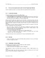
Process Interrupt Generation with the 434-7 Digital Input Module
The 434-7 digital input module is an interrupt module with programmable interrupt generation.
9.3.1
Function Description
The process interrupts are processed in two different ways:
•
Interrupt-initiating inputs can be identified by the control program.
•
A yellow LED lights up on the module and a relay contact is closed (the relay contact can be
accessed externally via the "MELD" outputs). This signal remains even in the event of power
failure and can be reset by applying 24 V to the 24 V RESET input.
Although the 434-7 digital input module has only eight inputs, it occupies two bytes in the input
I/O area and two bytes in the output I/O area, i.e. you can access two bytes of inputs and two
bytes of outputs (input byte and output byte each have the same address). Because the 434-7
digital input module occupies two I/O bytes, the IM 306 has to be set to 16 channels for this
module.
The addresses of the two consecutive I/O bytes occupied by the 434-7 are referred to in the follo-
wing as "module address" and "module 1".
•
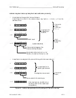
Use the two bytes of outputs in the restart OB for initializing the module (the "module
address" byte indicates which input triggers the interrupt and the "module 1" byte
determines the type of the interrupt-initiating edge)
•
You must use the two bytes of inputs when
- you want to scan the status of the inputs (scan the "module address" byte)
- you want to indentify inputs which have triggered the interrupt (scan the "module
1" byte; only in interrupt program).
The status of the inputs must be scanned direct (L PY) since it is
not transferred to the PII.
9.3.2
Start-Up
Assign a slot address to the module; the IM 306 interface module is to be set to 16 channels
for the 434-7 digital input module!
9.3.3
Initialization in Restart OBs
The following must be programmed in the RESTART blocks OB21 and OB22:
•
Which inputs are to trigger an interrupt
•
Whether the interrupt is to be triggered by a rising or falling edge.
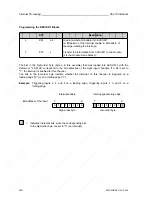
This information is stored in two bytes which the program in OB21 or OB22 transfers to the
module.
In the "module address" byte, mark which inputs are to trigger an interrupt, and in the "module
1" byte, mark which edge is to trigger the interrupt.
EWA 4NEB 811 6130-02b
9-5
Summary of Contents for SIMATIC S5-115U
Page 6: ...EWA 4NEB 811 6130 02b ...
Page 16: ...EWA 4NEB 811 6130 02b ...
Page 18: ...EWA 4NEB 811 6130 02b ...
Page 26: ......
Page 62: ...EWA 4NEB 811 6130 02b ...
Page 64: ...EWA 4NEB 811 6130 02b ...
Page 67: ......
Page 74: ......
Page 79: ......
Page 80: ......
Page 81: ......
Page 82: ......
Page 83: ......
Page 84: ......
Page 97: ......
Page 98: ......
Page 99: ......
Page 114: ...EWA 4NEB 811 6130 02b ...
Page 280: ...EWA 4NEB 811 6130 02b ...
Page 372: ...EWA 4NEB 811 6130 02b ...
Page 432: ...EWA 4NEB 811 6130 02b ...
Page 442: ......
Page 528: ...EWA 4NEB 811 6130 02b ...
Page 590: ......
Page 591: ......
Page 592: ......
Page 593: ......
Page 594: ......
Page 600: ...EWA 4NEB 811 6130 02b ...
Page 602: ...EWA 4NEB 811 6130 02b ...
Page 604: ...EWA 4NEB 811 6130 02b ...
Page 624: ...EWA 4NEB 811 6130 02b ...
Page 632: ...EWA 4NEB 811 6130 02b ...
Page 644: ...EWA 4NEB 811 6130 02b ...
Page 646: ...EWA 4NEB 811 6130 02b ...
Page 652: ...EWA 4NEB 811 6130 02b ...
Page 654: ...EWA 4NEB 811 6130 02b ...
Page 660: ...EWA 4NEB 811 6130 02b ...
Page 662: ...EWA 4NEB 811 6130 02b ...
Page 666: ...EWA 4NEB 811 6130 02b ...
Page 668: ...EWA 4NEB 811 6130 02b ...
Page 674: ...EWA 4NEB 811 6130 02b ...


