


System overview
3.3 System configuration
PN/M-Bus LINK
12
Operating Instructions, 03/2018, A5E44260928-AA
3.3
System configuration
System configuration
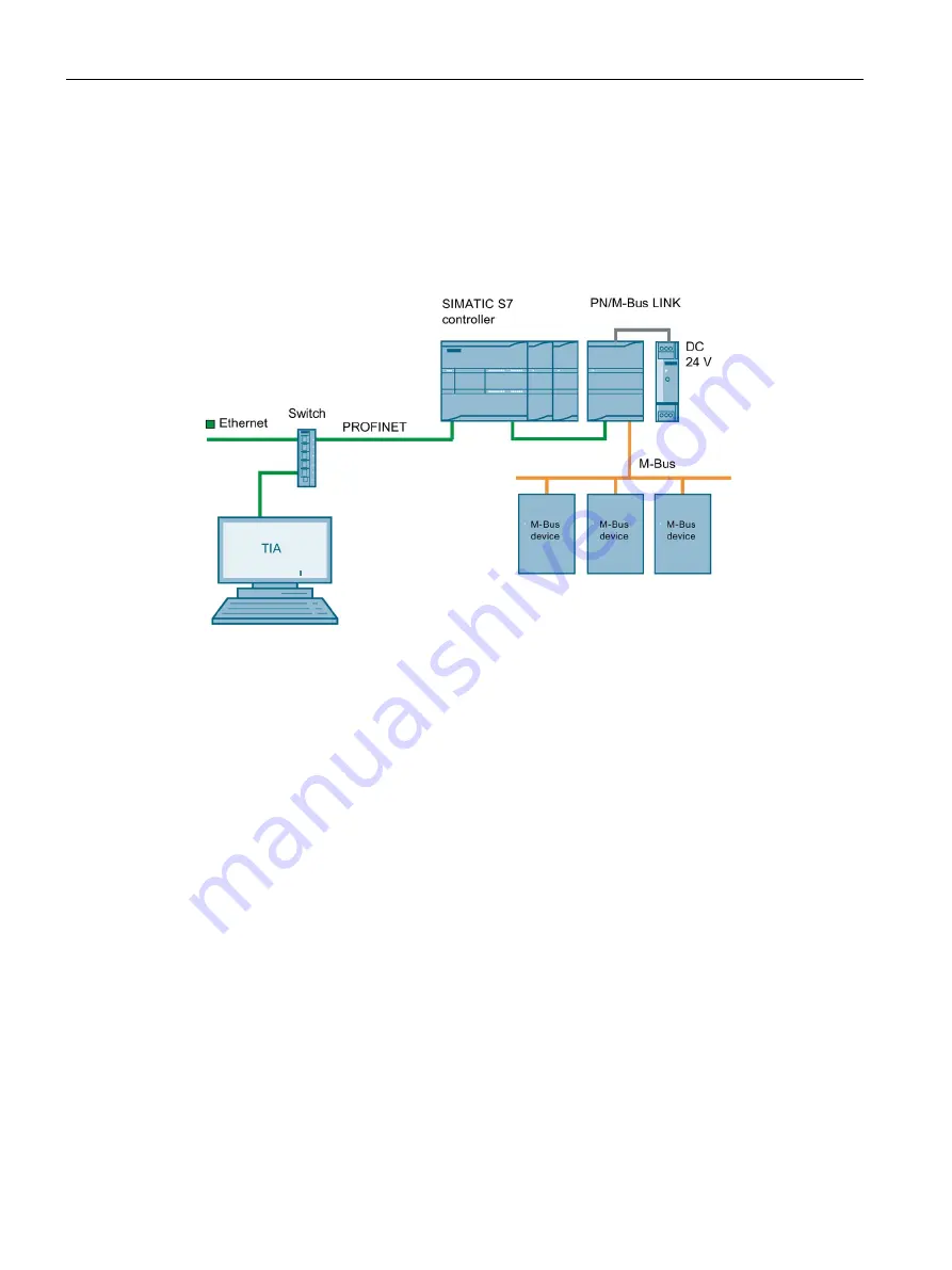
The following figure shows a basic system configuration with PN/M-Bus LINK as a
communication gateway between a PROFINET network and an M-Bus network.
Figure 3-2
System configuration with PN/M-Bus LINK
Purpose and function of the system components
PN/M-Bus LINK enables the connection of the M-Bus to PROFINET.
PN/M-Bus LINK communicates with the CPU of the S7 controller exclusively via the
PROFINET interface.
From a PROFINET point of view, PN/M-Bus LINK is an IO device according to Conformance
Class B (CC-B).
Cyclic data exchange between the PN/M-Bus LINK and the connected SIMATIC-CPU is
performed by updating the IO image. Acyclic communication is handled via the "Read Data
Record" service.
The power is supplied to the PN/M-Bus LINK either via an external power supply unit with
24 V DC or via the 24 V power supply of the SIMATIC S7 system.
The TIA Portal is used for configuring. A GSDML file is available for this purpose.


