9.7.9
Step 3 - Adding explanatory text
Prerequisites
● The "RMT1.pdl" process picture is open in the Graphics Designer.
● The block icon for "PARA_DOS_RM1_SEL" is available.
Procedure
The plant operator needs to be able to understand the setting for selecting the respective
reactor. You use a text field in order to provide this explanation. You have already used text
fields when labeling the plant.
1. Insert a text field – use the "Standard Objects/Static Text" object to do this.
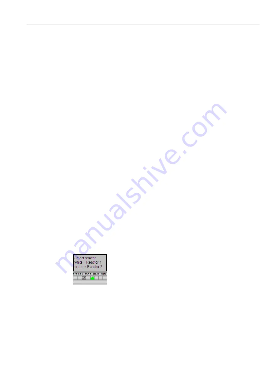
2. Enter the following text: "Select reactor: white = Reactor 1, green = Reactor 2".
Press <Shift + Return> to create a line break.
3. Format the text fields using the style palette:
– Frame invisible - "Line weight/Invisible" setting
– Fill transparent - "Fill Pattern/Transparent" setting
4. Select the "Properties" tab.
5. Select "Effect".
6. Double-click the "Global color scheme" attribute in the right-hand area of the window.
"No" is now entered in the "Static" column.
7. Close the "Object Properties" window.
8. Drag a frame around the explanatory text. Use the "Standard Objects/Rectangle" object for
this purpose.
9. Format the text fields using the style palette:
– Thickness of the frame – "Line Weight/3 Pixel" setting
– Fill transparent - "Fill Pattern/Transparent" setting
10.Position the objects as shown in the figure below:
11.Drag a frame around all the objects using the mouse.
12.Select Edit > Group > Group.
This groups all the objects into one single object and makes it easier to move them.
13.Position the objects between the reactors.
Configuring the operator station
9.7 Creating the process picture
PCS 7 SMART Getting Started - Part 1 (V9.0 with APL)
Getting Started, 12/2017, A5E42181435-AA
167


