


2-13
SIMATIC PC RI25/45, Technical Description
C79000-G7076-C808-01
2.8
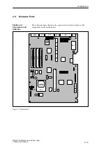
Hardware Ports
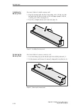
The following figure illustrates the connector and switch positions of the
components on the motherboard.
X12
X4
X3
X402
X11
X10
X800
X9
X7
1 2 3 4 5 6
S2
S1
X18
X17
Batt.
X24
X22
X21
X20
X19
X1
X23
X80
X90
X6
1 2 3 4 5 6
X15
CPU
X34
X801
Figure 2-5 Motherboard
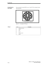
Position of
Connectors and
Switches
Motherboard