background image


Installing and connecting the device 


3.3 Connecting the device 

SIMATIC IPC347E 
Operating Instructions, 09/2018, A5E41134132-AE 

33


Procedure  


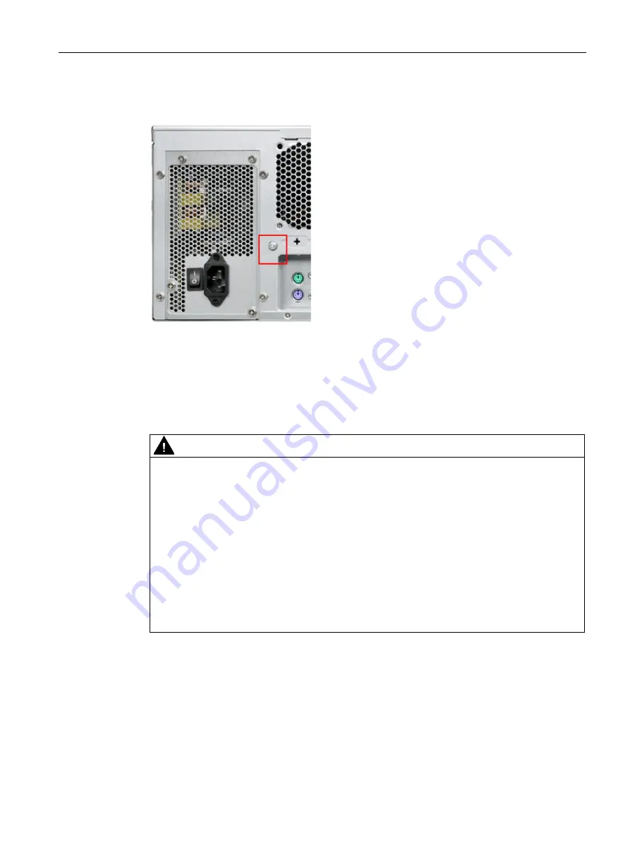
1.


Connect the identified function earth 

connection to the protective conductor of the 

control cabinet in which the device is 

installed. 
The minimum cross-section of the function 

earth is 2.5 mm

2

3.3.3


Connecting the power supply 

Note before you connect the device  


WARNING 

Injuries to persons or damage to property when operated on an incorrect power supply 

system 
If you connect the device to an unsuitable power supply, the device receives voltages and 

currents too high or too low. 
Injuries to persons, malfunctions or a damage to the device can result. 
Note the following information regarding the power supply system: 


The permitted nominal voltage of the device must correspond to the local mains voltage. 


Do not operate the device in non-grounded or impedance-grounded networks (IT 

networks). 


Operate the device only in grounded power networks (TN networks in accordance with 

IEC 60364-1). 


Summary of Contents for SIMATIC IPC347E

Page 1: ...______ SIMATIC Industrial PC SIMATIC IPC347E Operating Instructions 09 2018 A5E41134132 AE Preface Overview 1 Safety instructions 2 Installing and connecting the device 3 Commissioning the device 4 Installing hardware expansions 5 Device maintenance 6 Technical specifications 7 Appendix Motherboard A Appendix BIOS B Appendix The pin definition of ATX power supply output connector C Appendix Techni...

Page 2: ...ly by personnel qualified for the specific task in accordance with the relevant documentation in particular its warning notices and safety instructions Qualified personnel are those who based on their training and experience are capable of identifying risks and avoiding potential hazards when working with these products systems Proper use of Siemens products Note the following WARNING Siemens prod...

Page 3: ... technical support https support industry siemens com Conventions The terms PC or device are sometimes used in place of the product name SIMATIC IPC347E in these operating instructions Basic knowledge required Knowledge of personal computers and Microsoft operating systems is required General knowledge of automation control engineering is recommended Position in the information landscape The docum...

Page 4: ...rsions of these operating instructions Table 1 Versions for the IPC347E Version Comments 02 2016 The first edition 08 2017 The second edition 10 2017 The third edition 07 2018 Add the workaround for the Windows boot problem caused by SATA selection 09 2018 Add the information that complies with UL61010 ...

Page 5: ... information 28 3 2 2 Mounting location and position 29 3 3 Connecting the device 31 3 3 1 Connection information 31 3 3 2 Connecting the function earth 32 3 3 3 Connecting the power supply 33 3 3 4 Connecting the device to networks 35 3 3 5 Dual monitoring 36 4 Commissioning the device 37 4 1 Requirements for commissioning 37 4 2 Initial commissioning 37 4 3 Switching off the device 38 5 Installi...

Page 6: ...s and software 67 7 Technical specifications 69 7 1 Certificates and approvals 69 7 2 Guidelines and declarations 72 7 2 1 Electromagnetic compatibility 72 7 3 Dimension drawings 72 7 3 1 Dimension drawing of the device 72 7 3 2 Dimensional drawings for the installation of expansion cards 73 7 3 3 Dimension drawing for the use of telescopic rails 74 7 4 Technical data 74 7 4 1 General technical sp...

Page 7: ...G_2 SATA3G_3 SATA3G_4 96 A 3 13 Battery socket 96 A 4 Installing drivers 97 A 4 1 Installing the drivers on Windows 7 97 B Appendix BIOS 101 B 1 BIOS getting started 101 B 2 Main setup 102 B 3 Advanced setup 104 B 4 Chipset setup 111 B 5 Boot Setup 115 B 6 Security setup 117 B 7 Save and Exit 119 C Appendix The pin definition of ATX power supply output connector 121 D Appendix Technical support 12...

Page 8: ...Table of contents SIMATIC IPC347E 8 Operating Instructions 09 2018 A5E41134132 AE ...

Page 9: ...47E is an industrial PC in 19 rack format design 4U Powerful processors up to Intel Core i5 4th generation No additional dust protection measures required thanks to filter mat and overpressure ventilation Robust all metal enclosure Variety of interfaces Lockable front cover Prepared for mounting on telescopic rails ...

Page 10: ...stem Windows 7 Ultimate Multi Language English version is preinstalled 1 64 Bit SP1 Without Display integrated graphic engine support up to 1920 x1200 pixels Power Supply 100V to 240V AC Expansion slot 4 x PCI 1 x PCIe x 1 Gen2 0 1 x PCIe x 8 2 lanes Gen2 0 1 x PCIe x 16 Gen2 0 Interface 2 x USB 3 0 rear 5 x USB 2 0 2x in the front 2x in the rear 1x internal 2 x COM 2 RS232 RS422 RS485 2 x Etherne...

Page 11: ...0 devices compatible with USB 1 1 1 HDD status display Drive bay Power status display 1 Each USB port can be disabled enabled separately by disabling enabling the associated USB port in BIOS On how to disable enable the USB port see USB configuration in Advanced setup Page 104 Display Meaning LED Description HDD Display for hard disk access Off No accessing Green flashing Accessing data Power PC o...

Page 12: ... the device SIMATIC IPC347E 12 Operating Instructions 09 2018 A5E41134132 AE Rear view Power supply Function earth Air outlet Interfaces Extensible interface Expansion slots for 4 PCI 1 PCle 1 1 PCIe x 8 2 lanes 1 PCIe x 16 ...

Page 13: ... headset 3 5 mm phono jack Microphone pink Connection for microphone 3 5 mm phono jack USB Port 1 2 Connections for USB 3 0 devices compatible with USB 2 0 1 1 USB Port 2 2 Connections for USB 3 0 devices compatible with USB 2 0 1 1 USB Port 4 2 Connections for USB 2 0 devices compatible with USB 1 1 USB Port 3 2 Connections for USB 2 0 devices compatible with USB 1 1 DVI D Port Connection for CRT...

Page 14: ...422RX 3 TXD 422TX 485TX 485RX 4 DTR 422RX 5 GND GND GND 6 DSR 7 RTS 8 CTS 9 RI LAN port LED indications Activity Link LED Speed LED Status Description Status Description Off no link established Off link speed 10Mbps Orange link established Red link speed 100Mbps Blink transferring data Green link speed 1Gbps Power supply The following figure shows the connector for the IPC347E power supply ...

Page 15: ...out the power plug when the device is not in use Disconnect the device from the network by additional measures for example with an isolating switch NOTICE Make sure the disconnect devices main readily operable The MAINS plug or an appliance coupler of the apparatus is used as the disconnect device the disconnect device shall remain readily operable On off switch The following figure shows the loca...

Page 16: ... The following figure shows the position of the on off button at the front of the device The on off reset button has three functions Switch on the PC press the on off button once shortly Shut down the operating system and switch off PC press the on off button once shortly 1 Switch off PC without shutting down the operating system press for more than 4 seconds hardware reset 1 You can set this oper...

Page 17: ...ents should only be connected to an enterprise network or the internet if and to the extent such a connection is necessary and only when appropriate security measures e g firewalls and or network segmentation are in place For additional information on industrial security measures that may be implemented please visit https www siemens com industrialsecurity Siemens products and solutions undergo co...

Page 18: ...rom the main power supply as follows before performing work on the device or when the device will not be used over an extended period of time If the device is not mounted in a control cabinet Shut down the operating system and pull the power plug on the rear of the device If the device is mounted in a control cabinet Shut down the operating system and switch the AC circuit breaker to Off Properly ...

Page 19: ...e to find out which device and system expansions are suitable for installation Please observe the information on electromagnetic compatibility in the technical specifications CAUTION Fire hazard due to overheating of the device Expansion cards generate additional heat The device can overheat or cause a fire Observe the safety and installation instructions for the expansion cards If necessary insta...

Page 20: ...battery Page 56 in the operating instructions For any requirements on product maintenance contact Siemens Technical support Page 123 Do not throw lithium batteries into fire do not solder on the cell body do not recharge do not open do not short circuit do not reverse polarity do not heat above 100 C and protect from direct sunlight moisture and condensation High frequency radiation NOTICE Uninten...

Page 21: ...influence the sound pressure for example the operating system equalizer software firmware and driver Excessive sound pressure from headphones can result in impaired hearing or even loss of hearing Set the volume control and equalizer to the lowest value before you put on the headphones Keep checking the volume control setting Only use headphones and software approved by the manufacturer CAUTION Pr...

Page 22: ...th the maximum ambient temperature Tma specified by the manufacturer B Reduced Air Flow Installation of the equipment in a rack should be such that the amount of air flow required for safe operation of the equipment is not compromised C Mechanical Loading Mounting of the equipment in the rack should be such that a hazardous condition is not achieved due to uneven mechanical loading D Circuit Overl...

Page 23: ...on the device Operate the device only in accordance with the ambient conditions specified in the technical specifications Do not expose the device to direct sunlight or other strong sources of light Without additional measures such as a supply of clean air the device may not be used in locations with harsh operating conditions caused by acidic vapors or gases Protect the device against dust moistu...

Page 24: ...Safety instructions 2 4 Notes on use SIMATIC IPC347E 24 Operating Instructions 09 2018 A5E41134132 AE ...

Page 25: ...stallation location 4 Keep the original packaging in case you have to transport the unit again NOTICE Damage to the device during transport and storage If a device is transported or stored without packaging shocks vibrations pressure and moisture might impact the unprotected device A damaged packaging indicates that ambient conditions have already had an impact the device The device might be damag...

Page 26: ...extreme fluctuations in temperature during the transportation for example in cold weather moisture could condensed on or inside the device Moisture can result in short circuits and damage the device In order to prevent damage to the device observe the following rules If a condensation happens wait approximately 12 hours or until the device is completely dry before switching it on 7 Keep the enclos...

Page 27: ...nified Siemens address for product liability COA label The COA label Certificate of Authenticity is only provided with a pre installed Windows operating system Open the front door to check for the COA label Component label The component label is located inside the front door Identification data Where is it Ethernet address 1 MAC address Ethernet address 2 MAC address Normally 1 For example If MAC ...

Page 28: ...py the Ethernet addresses from the component label to the table The Ethernet addresses can also be found in the BIOS setup F2 key under Main System Information entries LAN 1 MAC and LAN 2 MAC 3 2 Installing the device 3 2 1 Installation information NOTICE Risk of fire If you install the device in an unapproved mounting position or if you do not observe the ambient conditions the device can overhea...

Page 29: ...c regulations Provide adequate volume in the switchgear cabinet for air circulation and heat transport Keep at least 10 cm between the device and the switchgear cabinet Do not cover the vent slots of the device Ensure that the maximum air intake temperature measured 5 cm before the air intake opening does not exceed 40 C The maximum air intake temperature must be accounted for especially when sizi...

Page 30: ...n of the mounting holes for angle brackets or telescopic rails Threaded holes for 3A68 508 R L telescopic rails from the company KING SLIDE WORKS CO LTD or other telescopic rails match the dimensional and technical re quirements CAUTION Risk of short circuit and electric shock Some small widget or water may drop into the device from the holes in the rear of the device Make sure the rear cover of d...

Page 31: ...safety socket of the building installation is freely accessible and located as close as possible to the device especially if the power plug is secured by a power plug lock WARNING Risk of lightning strikes A lightning flash may enter the mains cables and data transmission cables and jump to a person Death serious injury and burns can be caused by lightning Take the following precautions Pull out t...

Page 32: ... also improves the discharge of interference generated by external power cables signal cables or cables for I O modules to ground The connection for the function earth is labeled with the following symbol Note The function earth cannot connect hazard live parts WARNING Electric shock and risk of fire High voltage might be present in a defective device which can cause fire or an electric shock if t...

Page 33: ...Injuries to persons or damage to property when operated on an incorrect power supply system If you connect the device to an unsuitable power supply the device receives voltages and currents too high or too low Injuries to persons malfunctions or a damage to the device can result Note the following information regarding the power supply system The permitted nominal voltage of the device must corres...

Page 34: ...e following features 230 V supply voltage of the USA and Canada Type SJT with three conductors The connector must be compliant with NEMA 5 15 Conductor cross section 18 AWG Cable length 4 5 m 120 V supply voltage of the USA and Canada Type SJT with three conductors The connector must be compliant with NEMA 5 15 Conductor cross section 18 AWG Cable length 4 5 m 240 V supply voltage Type SJT with th...

Page 35: ...onments and networks Ethernet Wake on LAN and Remote Boot are supported You can use the integrated Ethernet interfaces 10 100 1000 Mbps for communication and data exchange with automation devices such as SIMATIC S7 You need the SOFTNET S7 software package for using the SIMATIC S7 to communicate PROFINET PROFINET can be operated via Standard Ethernet interfaces RT SIMATIC NET Use this software pack...

Page 36: ...tructions 09 2018 A5E41134132 AE 3 3 5 Dual monitoring You can operate on up to two monitors with the VGA and DVI D cables The output on the extended monitor can be the same as the main monitor or the extension desktop of the main monitor You can configure it in windows screen and display setting ...

Page 37: ...lled the operating system is set up automatically on the device after the initial switch on The commissioning procedure in this chapter is only applicable to the IPCs with operating system For the configurations without operating system pre installed contact the operating system provider to install the operating system firstly NOTICE Faulty installation If you change the default values in the BIOS...

Page 38: ...e Once the operating system has been set up the device may restart Result The interface of the operating system is displayed every time you turn on the device and after the startup routine 4 3 Switching off the device Shutting down the operating system For Windows operating systems Select Start Shut down or Briefly press the on off button unless otherwise configured in the power options Informatio...

Page 39: ...me If the device was not mounted in a control cabinet Shut down the operating system and pull the power plug on the rear of the device If the device was mounted in a control cabinet Shut down the operating system and switch the AC circuit breaker to Off The device is switched off and fully disconnected from the mains voltage No trickle current is flowing Hardware reset You can perform a hardware r...

Page 40: ...Commissioning the device 4 3 Switching off the device SIMATIC IPC347E 40 Operating Instructions 09 2018 A5E41134132 AE ...

Page 41: ...troyed by electrostatic charges This can result in malfunctions and damage to the machine or plant Make sure you take precautionary measures when you open the device for example when opening device doors device covers or the housing cover Limitation of liability All technical specifications and approvals apply only to expansions which are approved by the Siemens AG We are not liable for functional...

Page 42: ...dules conforming to PCI specification 2 3 32 bit 33 MHz Rev 2 3 and PCIe specification 2 0 The dimensions of the cards cannot exceed the specified dimensions If the height of the card exceeds the specified dimension you may experience contact problems malfunctions and difficulties with the assembly The permitted expansion card dimensions are specified in the section Dimensional drawings for the in...

Page 43: ...ng Instructions 09 2018 A5E41134132 AE 43 5 2 2 Installing expansion cards Requirements The device is disconnected from the mains The device is open Procedure 1 Remove the retaining screw and remove the card holder 2 Remove the slot bracket of the slot for the expansion card ...

Page 44: ...E 44 Operating Instructions 09 2018 A5E41134132 AE 3 Insert the expansion card into the slot 4 Secure the expansion card with the designated screw 5 Loosen the bracket by unscrewing its screw and place it on the expansion card 6 Secure the bracket 7 Close the device ...

Page 45: ... The drive modules are horizontal slot DVD ROMs DVD burners and HDDs with a 5 25 to 3 5 inch converter may be installed in the slots 5 3 2 Removing the drive module Requirement The device is disconnected from the mains PH2 screwdriver Procedure 1 Unlock the front door and open the right front door 2 Remove the top cover 3 Disconnect the power supply and data cables ...

Page 46: ...erating Instructions 09 2018 A5E41134132 AE 4 Remove the highlighted screws The forth screw is behind the right handle 5 Lift the drive cage completely out of the device 5 3 3 Installing drives or hard disks Requirement The drive carrier has been removed PH2 screwdriver ...

Page 47: ...attach two mounting brackets or a 3 5 5 25 mounting rack for the drive 2 Remove the retaining screws and remove the cover plate for the expansion drive 3 Secure the drive to the slot or with 4 screws The screws to be installed on the right side of the slot are highlighted in the figure below 4 Install the driver cage again 5 Connect the power and data cables to the drive ...

Page 48: ...uirement The device is disconnected from the mains The device is opened The drive bay is taken out of the chassis Procedure for removing the hard disk drive Loosen the four screws on the drive bay plate and remove the drive from the drive bay Procedure for installing the hard disk drive Place the drive onto the drive bay plate and secure the drive with four screws ...

Page 49: ...on devices you may damage the device or violate the safety requirements and regulations on RF suppression Contact your technical support team or the sales team from whom you purchased your PC to find out which system expansion devices can be installed NOTICE Risk of device damage If you install or exchange system expansions and damage your device the warranty becomes void CAUTION Risk of motherboa...

Page 50: ...electrostatical sensitive devices make sure that persons the workstation and devices tools and packaging used are properly grounded This way you avoid static discharge Avoid direct contact As a general rule do not touch electrostatic sensitive devices except in the case of unavoidable maintenance work Hold the modules at their edge so that you do not touch the connector pins or conductor paths Thi...

Page 51: ...replacement of those PC components that are subject to wear in accordance with the intervals for replacement indicated in the table below Component Replacement interval Hard disk drive 3 years CMOS backup battery 5 years Fan 3 years Filter mat Depending on the degree of soiling1 1 The filter can be reused after cleaning 6 3 2 Replacing filters Requirement The device is disconnected from the mains ...

Page 52: ...on of the arrow to open the left front door 3 Unscrew the marked screws 4 Pull the marked screw to open the fan bracket 5 Remove the filter in the direction of the arrow 6 Follow the steps for removing the filter in reverse order to install a new one 6 3 3 Beep code Beep code Beeps Description 1 short beep Power on correctly 4 short beeps Memory error 5 short beeps Keyboard error ...

Page 53: ...me type Procedure Removing the fan 1 Unlock the front cover with the key 2 Pull the handle in the direction of the arrow to open the left front door 3 Unscrew the marked screws 4 Pull the marked screw to open the fan bracket 5 Remove the highlighted screws 6 Remove the fan in the direction of the arrow 7 Pull the fan plug from the connector Procedure Installing the fan To install the fan follow th...

Page 54: ...type Module Size Description DDR3 SDRAM 8GB DDR3 1600 1024M x 64 UDIMM 240pin DDR3 SDRAM 4GB DDR3 1600 512M x 64 UDIMM 240pin DDR3 SDRAM 2GB DDR3 1600 256M x 64 UDIMM 240pin To install the memory module WARNING Only install memory modules designed for the default motherboard Recommend to select memory modules with the same brand capacity speed and chips if you use multiple Memory Modules Unplug th...

Page 55: ...l memory module on motherboard memory sockets 1 Press the retaining clips outward to unlock the memory socket 2 Align a memory module on the socket so the notch on memory matches the alignment key on memory socket 3 Insert and press the memory module into the socket until the retaining clips snap back to the original place and the Memory Module is seated properly ...

Page 56: ...der on the cell body do not recharge do not open do not short circuit do not reverse polarity do not heat above 100 C and protect from direct sunlight moisture and condensation NOTICE Disposal of batteries Batteries do not belong in domestic garbage The user is legally obliged to return used batteries Used batteries pollute the environment as special waste You as a user are liable to prosecution i...

Page 57: ...e chapter Jumpers Page 84 and chapter Battery socket Page 96 Reconfiguring the BIOS setup When a battery is replaced the configuration data of the device is deleted and must be reconfigured in the BIOS setup 6 4 4 Removing the power supply Requirement The device is disconnected from the mains The top cover is opened All connection cables are unplugged PH2 screwdriver Procedure 1 Disconnect the pow...

Page 58: ... Remove the unnecessary modules from the slots for example the expansion card 2 Note the assignment of all cables to the motherboard 3 Disconnect all cables from the motherboard 4 Remove the nine screws indicated in the following figure 6 4 6 Replacing the processor Requirement The device is disconnected from the mains The device is opened A suitable processor Only an approved processor is permitt...

Page 59: ...herboard may get damaged during changing the processor Don t change the processor unless it is really necessary Procedure 1 Unlatch the fan rack on the heat sink and remove it 2 Remove the highlighted fan connector 3 Remove the highlighted screws The fourth screw is hidden by the heat sink in the figure 4 Remove the heat sink 5 Unlock the socket and lift the socket cover ...

Page 60: ...r type and clock frequency If you use a processor of a different type perform the BIOS update firstly During the BIOS update the microcode matching the processor is loaded Contact the SIEMENS support to update the BIOS if you changed a different processor Note Damage to the processor due to high clock frequency If the installed processor is operated with a higher clock frequency than permitted it ...

Page 61: ... from the recovery DVD The Documentation and Drivers DVD contains the documentation and the hardware drivers With the restore DVD The restore DVD is included in the scope of delivery when you have ordered a device with operating system The restore DVD includes Operating system with installed hardware drivers 6 5 2 Restoring the delivery state You can restore the original factory software using the...

Page 62: ...47E 62 Operating Instructions 09 2018 A5E41134132 AE Procedure 1 Insert the Restore DVD into the DVD drive 2 Reboot the device 3 Press the F10 key and set CD DVD as the priority 1 in the boot menu 4 Reboot the device 5 Click Next button to start the restoration ...

Page 63: ...tition Note The selected hard disk must be the same type as the factory shipped hard disk NOTICE Risk of data lost If Format selected Partition is set all data on the selected drive system partition will be deleted All data user settings and all authorizations or license keys on the selected drive will be lost All data on the selected drive will be completely deleted reformatted and overwritten wi...

Page 64: ...n a boot menu is displayed 4 In the boot menu select the optical drive using the cursor keys It is identified by a P in front of the SATA port number Example P3 OPTIARC DVD ROM DDU1681S 5 Confirm the selection by pressing ENTER 6 Immediately press any key when you see the following prompt to install the operating system from the Recovery DVD Press any key to boot from CD or DVD After a few seconds...

Page 65: ...p partitions and integrating storage controllers unknown to the operating system You can set up partitions during the installation process and integrate storage controllers that are unknown to the operating system To do so select Custom advanced when prompted for the installation type in the Install Windows installation program The following dialog windows are then available Example 1 Windows inst...

Page 66: ...ple if the data medium was not formatted in the required NTFS format 1 Make sure that the partition on which you want to install the operating system is large enough at least 20GB and is set up with an NTFS file system The recommended minimum size of this partition varies depending on the operating system how much RAM you have available and how much additional software you want to use Information ...

Page 67: ...essed 6 5 4 Installing drivers and software Install the drivers and software from the Documentation and Drivers DVD that ships with the product Procedure 1 Insert the DVD 2 Double click index htm to open the navigation page 3 Select Drivers from the index 4 Select the operating system you use 5 Install the required driver For more information on installing the drivers see Installing the drivers on...

Page 68: ...Device maintenance 6 5 Installing the software SIMATIC IPC347E 68 Operating Instructions 09 2018 A5E41134132 AE ...

Page 69: ... the device is supplied with preinstalled software you must observe the corresponding license agreements CE marking 2004 108 EC Directive of the European Parliament and of the Council of 15 December 2004 on the approximation of the laws of the Member States relating to electromagnetic compatibility until 19 04 2016 2014 30 EU Directive of the European Parliament and of the Council of 26 February 2...

Page 70: ...ement This equipment has been tested and found to comply with the limits for a Class A digital device pursuant to Part 15 of the FCC Rules These limits are designed to provide reasonable protection against harmful interference when the equipment is operated in a commercial environment This equip ment generates uses and can radiate radio frequency energy and if not installed and used in accordance ...

Page 71: ...ion for Eurasion Customs Union EAC Eurasian Conformity Customs union of Russia Belarus and Kazakhstan Declaration of conformity according to Technical Regulations of the Customs Union TR CU KOREA This product meets the requirements of Korean certification This product satisfies the requirement of the Korean Certification MSIP Mark 이 기기는 업무용 A 급 전자파 적합기기로서 판매자 또는 사용자는 이 점을 주의하시기 바라며 가정 외의 지역에서 사용하는...

Page 72: ...signed for the following areas of application Scope of application Requirements for Emission Immunity Industrial area IEC 61000 6 4 2011 IEC 61000 6 2 2005 WARNING This is a class A product In a domestic environment this product may cause radio interference in which case the user may be required to take adequate measures 7 3 Dimension drawings 7 3 1 Dimension drawing of the device Front view and p...

Page 73: ...cifications 7 3 Dimension drawings SIMATIC IPC347E Operating Instructions 09 2018 A5E41134132 AE 73 All dimensions are in mm 7 3 2 Dimensional drawings for the installation of expansion cards Long PCI card PCIe card ...

Page 74: ... Applicability of technical specifications The following technical specifications only apply under the following conditions The default configuration of the device is not changed The device is in good working order The fan cover and filter mat are installed The device is closed Dimensions 481 177 509 W H D in mm For detailed information on dimensions refer to Dimension draw ing of the device Page ...

Page 75: ... Category II Safety Protection class Protection class I compliant with IEC 61140 Safety regulations IEC60950 1 GB4943 1 2011 Electromagnetic compatibility Emitted interference Conducted Emission AC IEC 61000 6 4 A1 CISPR 22 0 15 0 5 MHz 79 dB µV QP 66 dB µV A 0 5 30 MHz 73 dB µV QP 60 dB µV A Radiation Emission IEC 61000 6 4 CISPR 22 30 230 MHz 40 dB µV m QP 10 m distance 230 1000 MHz 47 dB µV m Q...

Page 76: ...nt 10 C h no condensation Storage transportation 20 C to 60 C Gradient 20 C h no condensation Relative humidity Tested in accordance with IEC 60068 2 78 IEC 60068 2 30 Operation 5 to 80 at 25 C no condensation Gradient 10 C h no condensation Storage transportation 5 to 95 at 25 C no condensation Gradient 20 C h no condensation Atmospheric pressure Operation 1013 to 795 hPa 0 to 2000m Storage trans...

Page 77: ...onsumption PCIe x1 x8 1 lane and x16 slot 3 3 V 3 A 12 V 2 1 A 3 3 Vaux 0 4 A Max permitted power consumption per PCI slot 5 V 32 bit 5 V 5 A or 3 3 V 7 A 12 V 0 5 A 3 3 Vaux 0 4 A Max permitted power loss per PCI slot 25 W PCI modules with exclusive 5 V supply 25 W Max permitted power loss over all slots 75 W In total the 3 3 Vaux current of 1 2 A must not be exceeded Drives for configuration det...

Page 78: ...0 Hz color depth up to 32 bit pixels 1 Graphics controller Intel HD Graphics 3D engine integrated in processor 1 VGA s resolution is depends on the monitor Interfaces COM 1 COM 2 RS232 RS485 RS422 9 pin D sub plug COM 3 COM 4 On motherboard RS232 9 pin header VGA Connection of an analog monitor DVI D Connection of a digital monitor Keyboard PS 2 keyboard connection Mouse PS 2 mouse connection USB ...

Page 79: ... current max per mitted 2 25 A 25 A 16 A 16 A 0 8 A 3 A Total power consumption permit ted 210 W Efficiency of the power supply 1 AC power supply approx 85 230 V AC 120 V AC with typical load 50 and 82 230 V AC 120 V AC with full 100 or light load 20 1 Depends on the selected device configuration 2 The max permitted accumulated power of the 5 V and 3 3 V is 130 W 7 4 3 Basic power supply Voltage M...

Page 80: ...mains cable without proper earth connection can result in personal injury or even death by electric shock A mains cable is not included with IPC347E Make sure the cable you use provides a proper earth connection It is highly recommended that you use a mains cable from SIEMENS Plug type Region MLFB Grounded continental European plug Germany Denmark Nether lands Spain Belgium Austria Finland 6ES7 90...

Page 81: ...tion prior to delivery The most important settings are shown in the table below Tab Option Default setting Advanced Boot on LAN with PXE Disabled SATA configuration IDE HW monitor CPU FAN control Auto Mode HW monitor CHA FAN control Auto Mode For a detailed description of how to call up and operate the BIOS setup and which menus and setting options are available refer to the Appendix BIOS CAUTION ...

Page 82: ...Technical specifications 7 5 BIOS description SIMATIC IPC347E 82 Operating Instructions 09 2018 A5E41134132 AE ...

Page 83: ...lant Always completely disconnect the power cord from your motherboard when you are working on it Do not make connections while the power is on because a sudden rush of power can da mage the sensitive electronic components Always ground yourself to remove any static charge before touching the board Modern electronic devices are very sensitive to static electric charges Use a grounding wrist strap ...

Page 84: ...dard Before operating the motherboard make sure that the cables and the power connectors of all the attached hardware components are connected Turning on the power before you connected them the motherboard and the system components may get damaged and injure operator Make sure you securely attached the hardware components to the motherboard connectors slots sockets The screws are not allowed to co...

Page 85: ...f needle nose pliers may be helpful when working with jumpers If you have any doubts about the best hardware configuration for you application contact your local distributor or sales representative before you make any change Clear COMS CLRTC1 NOTICE Move the jumper back to protected mode after clearing CMOS ...

Page 86: ...Appendix Motherboard A 2 Jumpers SIMATIC IPC347E 86 Operating Instructions 09 2018 A5E41134132 AE COM2 5V 12V Selection COM2_V1 ...

Page 87: ...oard A 3 Internal Connector SIMATIC IPC347E Operating Instructions 09 2018 A5E41134132 AE 87 A 3 Internal Connector A 3 1 Fan connector The pin assignment in the table below applies to all fan connectors on motherboard ...

Page 88: ...TIC IPC347E 88 Operating Instructions 09 2018 A5E41134132 AE A 3 2 Front panel connector F_Panel1 F_Panel2 The front panel connector is used to connect cable to Chassis Front Panel and provide HDD LED Power LED Power Button and Reset Button functions ...

Page 89: ...ternal Connector SIMATIC IPC347E Operating Instructions 09 2018 A5E41134132 AE 89 A 3 3 Internal USB 2 0 connector USB 2_56 USB 2_78 Internal USB 2 0 Connectors provides 4 USB 2 0 Ports which require appropriate cable to support ...

Page 90: ... 3 Internal Connector SIMATIC IPC347E 90 Operating Instructions 09 2018 A5E41134132 AE A 3 4 Internal RS 232 COM Connector COM3 COM4 Internal COM Connectors provides 2 RS 232 Ports which require appropriate cable to support ...

Page 91: ...rd A 3 Internal Connector SIMATIC IPC347E Operating Instructions 09 2018 A5E41134132 AE 91 A 3 5 Internal DIO Connector DIO1 Internal DIO Connector provides 4 input and 4 output which require appropriate cable to support ...

Page 92: ...ternal Connector SIMATIC IPC347E 92 Operating Instructions 09 2018 A5E41134132 AE A 3 6 Internal LPT Connector LPT1 Parallel Port Internal LPT Connectors provides parallel port interface which require appropriate cable to support ...

Page 93: ...herboard A 3 Internal Connector SIMATIC IPC347E Operating Instructions 09 2018 A5E41134132 AE 93 A 3 7 Internal USB 2 0 Vertical Connector USB2_9 Internal USB 2 0 Vertical Connectors provides 1 Type A USB 2 0 Port ...

Page 94: ...4132 AE A 3 8 ATX power 24 pin connector EATX_PWR1 ATX Power 24 Pin connector is for ATX PSU plug Make sure you insert the ATX PSU plug on motherboard in the right orientation otherwise the plug cannot be inserted Note ATX Power 4 Pin connector must be connected otherwise the system cannot be turned on ...

Page 95: ...rd in the right orientation otherwise the plug cannot be inserted A 3 10 Intel CPU socket LGA1 Intel CPU Socket is for Intel 1155 Pin CPU Refer to the CPU installing section Replacing the processor Page 58 for detailed information A 3 11 DDR3 Memory sockets The motherboard provides two memory sockets which support two pieces of 240 pin DDR3 Memory Modules Refer to the chapter Installing memory mod...

Page 96: ...12 SATA 3 0 6 0 Gbps Port Connectors SATA6G_1 SATA6G_2 SATA3G_3 SATA3G_4 The motherboard provides four pieces of 7 pin SATA Port Connectors which support SATA devices through the connection of SATA Cable A 3 13 Battery socket The Battery Socket on the motherboard is for CR2032 Battery used for COMS data retention ...

Page 97: ...e OS list 5 Click the OS you use The available driver list opened Step 1 install the Intel chipset driver Note Install the Windows system patch before installing the Intel chipset driver 1 Click Chipset Intel Chipset H81 Express 2 Click to install the chipset driver 3 Click Run to allow the computer start the installation The system starts to extract file from driver package 4 Click Run to start t...

Page 98: ... the radio button next to Yes I want to restart this computer now and click Finish to reboot the computer Step 3 install the Realtek LAN driver 1 Click Ethernet onboard Realtek Onboard Network Adaptor 2 Click to install the chipset driver 3 Click Run to start the installation 4 Click Next to continue the installation 5 Click Install to start the driver installation 6 Click Finish to confirm the Re...

Page 99: ...nstall USB3 0 onboard interface 1 Click USB3 0 onboard interface Intel USB xHCI 3 0 2 Click to install the driver 3 Click Run to start the installation 4 Click Next to continue 5 Click Yes to accept License Agreement 6 Click Next to confirm the Readme File Information and move on 7 Click Next to continue setup 8 Check the radio button next to Yes I want to restart this computer now and click Finis...

Page 100: ...Appendix Motherboard A 4 Installing drivers SIMATIC IPC347E 100 Operating Instructions 09 2018 A5E41134132 AE ...

Page 101: ...r keyboard during the Power On Self Test POST when the SIEMENS logo is shown on screen The AptioTM TSE main BIOS setup menu is displayed You can access the other setup screens from the main BIOS setup menu such as Advanced or Chipset menus NOTICE If DELETE or ESC is not pressed POST continues its routines If the timing is missed for entering BIOS setup during POST a system reset is required by one...

Page 102: ...cular setup item for example date time F1 General Help To display the general help window F2 Previous Values To enable user to load previous values in BIOS setup Menu F3 Optimized Defaults To enable user to load optimized default values in BIOS Setup Menu F4 Save Exit To enable user to save the current configuration and exit BIOS Setup Menu ESC Exit The ESC Key allows user to discard any change ha...

Page 103: ...type in the value as you need Press Enter to jump to next filed 3 Press F4 key and save the change System time 1 Use arrow key to select the data 2 Navigate to the hour minute and second and type in the value as you need Press Enter to jump to next filed 3 Press F4 key and save the change Note Enter the time in the 24 hour format For example you should enter 06 30 00 for 6 30 AM Access level Acces...

Page 104: ... PCI X and PCI Express parameters S5 RTC wake settings In S5 RTC wake settings page you can enable or disable system to wake from S5 using RTC alarm NOTICE You cannot set both of the Wake system with Fixed Time and Wake system with Dynamic Time as Enabled at the same time Wake system with Fixed Time Follow the below instructions to enable system wake on alarm event at a specific time 1 Select the ...

Page 105: ...time Dynamic Digital IO In the Dynamic Digital IO page you can check and set the eight parameters of DIO0 DIO7 Dynamic Digital IO Follow the below instructions to set the Digital IO as the Input and Output 1 Select DIO0 Direction DIO7 Direction separately with the arrow keys and press Enter key 2 Select Input or Output as you need and press Enter key in the active window pop up If you set the Digi...

Page 106: ...er key in the active window pop up 3 Press F4 key and save the change Active process cores You can view and configure the number of cores to be enabled in each CPU package as the instruction below 1 Select Active process cores with the arrow keys and press Enter key 2 Select the corresponding active process cores as you need and press Enter key in the active window pop up 3 Press F4 key and save t...

Page 107: ...n view and configure USB parameters USB device The USB device shows the USB device detected by BIOS during POST If there is no device attached to the motherboard only 2 Hubs is shown USB support Follow the instruction below to enable or disable the USB support 1 Select USB support with the arrow keys and press Enter key 2 Select Enabled or Disabled as you need and press Enter key in the active win...

Page 108: ... LAN1 PXE OpROM RTK8111G LAN2 PXE OpROM with the arrow keys and press Enter key 2 Select Enabled or Disabled as you need and press Enter key in the active window pop up 3 Select Save changes and reset in the Save Exit menu and press the Enter key Resume on PCIE wake PME GbE Follow the instruction below to enable or disable the specific resume function 1 Select the specific resume function with the...

Page 109: ...C0h IRQ 11 IO 2B0h IRQ 11 IO 2B8h IRQ 11 IO 2C8h IRQ 11 IO 2D0h IRQ 11 IO 2D8h IRQ 11 Serial port 4 Auto IO 2C8h IRQ 5 IO 2B0h IRQ 5 IO 2B8h IRQ 5 IO 2C0h IRQ 5 IO 2D0h IRQ 5 IO 2D8h IRQ 5 Parallel port Auto IO 378h IRQ 5 IO 378h IRQ 5 6 7 10 11 12 IO 278h IRQ 5 6 7 10 11 12 IO 3BCh IRQ 5 6 7 10 11 12 STD Printer Mode SPP Mode EPP 1 9 and SPP Mode EPP 1 7 and SPP Mode ECP Mode ECP and EPP 1 9 Mode...

Page 110: ...an view and monitor the hardware status See the hardware monitor parameters below Item Description CPU Fan Control Set the control mode for CHA fan CHA Fan1 control Set the control mode for CHA fan1 CHA Fan2 control Set the control mode for CHA fan2 CPU temperature Show the CPU temperature system temperature Show the temperature inside chassis CPU Fan speed Show the CPU cooler fan speed CHA Fan1 s...

Page 111: ...tion Description Silent mode Within a certain range according to the system temperature to adjust the fan speed automatically Auto mode In the whole range according to the system temperature to adjust the fan speed automatically Disabled mode Always keep the maximum speed B 4 Chipset setup Chipset page Select Chipset from the BIOS setup page to enter the Chipset BIOS setup page The Chipset page is...

Page 112: ...he arrow keys and press Enter key 2 Select the display device you want and press Enter key 3 Press F4 key and save the change See the options for primary display setting below Option Description Auto Set to automatically detect Auto is the default setting IGFX Set IGFX device as primary display PEG Set PEG device as primary display Graphics Configuration Follow the instructions below to enable or ...

Page 113: ... Enter key 3 Press F4 key and save the change Table B 1 Azalia setting options Option Description Auto Azalia will be unconditionally disabled Auto is set as default Disabled Azalia will be unconditionally enabled Enabled Azalia will be enabled if present otherwise disabled Once Internal graphics is set as Enabled or Auto You can set the Azalia HDMI code Port B Use arrow keys to select the mode yo...

Page 114: ...C power loss 1 Select Restore AC Power Loss with the arrow keys and press Enter key 2 Select the mode you want and press Enter key 3 Press F4 key and save the change See options for restore AC power loss below Option Description Power Off Set to keep power off Power On Set to keep power on Last State Set as the last state before power failure Restore AC power loss is set to last state as default E...

Page 115: ... the instructions below to select your boot up screen 1 Select Quiet Boot with the arrow keys and press Enter key 2 Select the Disabled or Enabled as you want and press Enter key 3 Press F4 key and save the change See the quiet boot options below Option Description Disabled Set the motherboard to display the POST message Enabled Set the motherboard to display the SIEMENS logo This is the default s...

Page 116: ...ootable devices are attached the following items show up Bootable device Description Hard Disk Drive BBS Priorities All the boot options that are configured as Hard Disk Drive are displayed in this page You can change the priority as similar as changing the main boot option priorities The 1st boot option has the highest boot priority and ap pears at the boot option priorities and boot order Floppy...

Page 117: ...tion priorities and boot order B 6 Security setup Security setup NOTICE Risk of unauthorized modification for BIOS setting Everyone can access BIOS and change its setting if you don t set a password for BIOS Modify the BIOS setting arbitrarily may interfere with device function Set passwords for administrator and user In this way to avoid unauthorized access and modification to BIOS Security setup...

Page 118: ...tive 3 Re enter the password when you are asked to confirm the password in the screen popped up User password In the security setup page you can set a user level password for BIOS 1 Select User Password with the arrow keys and press Enter key 2 Enter a password of at least three characters in length The password can be up to 20 characters long and case sensitive 3 Re enter the password when you ar...

Page 119: ...ct Yes and press Enter key to save changes and reset Or Select No to quit the save After the system is rebooted the new system configurations take effect Discard changes and reset You can reboot the system without saving the changes with the following instructions 1 Select Discard Changes and Reset with the arrow keys and press Enter key 2 Select Yes and press Enter key to discard changes and rese...

Page 120: ...the settings as user defaults Or Select No to quit Restore user defaults You can restore the user default settings with the following instructions 1 Select Restore User Defaults with the arrow keys and press Enter key 2 Select Yes and press Enter key to load optimized defaults Or Select No to quit Boot override All the available boot options are listed below the Boot Override You can select any of...

Page 121: ...ructions 09 2018 A5E41134132 AE 121 Appendix The pin definition of ATX power supply output connector C ATX power supply can convert the AC 220 V power to the DC 3 3 V 5 V or 12 V power which are can be used in the internal computer ...

Page 122: ...Appendix The pin definition of ATX power supply output connector SIMATIC IPC347E 122 Operating Instructions 09 2018 A5E41134132 AE ...

Page 123: ...iemens com simatic tech doku portal Your local representative http www automation siemens com mcms aspa db en Pages default aspx Training center http sitrain automation siemens com sitrainworld AppLang en Industry MALL http mall automation siemens com When contacting your local representative or Technical Support please have the following information at hand Order number of the device MLFB BIOS ve...

Page 124: ...ness button For detailed information refer to the monitor operating instructions The power cord or the monitor cable is not connected Check whether the power cord is properly con nected to the monitor the system unit the grounded shockproof outlet Check whether the monitor cable has been properly connected to the system unit and to the monitor If the monitor screen still remains dark after you hav...

Page 125: ...sent does not open The device is switched off or the open close button is disabled by a software application Emergency removal of the data medium 1 Switch off the device 2 Insert a pointed object for example an opened paper clip into the emergency extraction opening of the drive Apply pressure carefully until the door opens 3 Pull the door out further with your hand The computer constantly re boot...

Page 126: ...Appendix Technical support D 2 Problem solving SIMATIC IPC347E 126 Operating Instructions 09 2018 A5E41134132 AE ...

Page 127: ...Rewritable Rewritable CD CF Compact Flash CGA Color Graphics Adapter Standard monitor interface CLK Clock pulse Clock signal for controllers CMOS Complementary Metal Oxide Semiconduc tors Complementary metal oxide semicon ductors COA Certificate of authentication Microsoft Windows Product Key CoL Certificate of License License authorization COM Communications Port Term for the serial interface CP ...

Page 128: ...al Commission IGD Integrated Graphics Device IP Ingress Protection Degree of protection IR Infrared Infrared IRDA Infrared Data Association Standard for data transfer via IR module IRQ Interrupt Request Interrupt request ISA Industry Standard Architecture Bus for expansion modules L2C Level 2 cache LAN Local Area Network Computer network that is limited to a local area LCD Liquid Crystal Display L...

Page 129: ...ect express High speed serial differential full duplex PtP interface with high data rate PCMCIA Personal Computer Memory Card Interna tional Association PI Protective Earth Protective conductor PEG PCI Express Graphics PFC Power Factor Correction Harmonic suppression for operation on public networks PG Programming device PIC Programmable Interrupt Controller Programmable interrupt controller POST ...

Page 130: ...ce SW Software TCO Total Cost of Ownership TFT Thin Film Transistor Type of LCD flat screen TTY Tele Type Asynchronous data transfer TxD Transmit Data Data transfer signal TXT Trusted Execution Technology Hardware implementation TWD Watchdog Time Watchdog monitoring time UEFI Unified Extensible Firmware Interface UL Underwriters Laboratories Inc US organization for tests and certifica tions accord...

Page 131: ... O Enables the direct assignment of a de vice e g network adapter to a virtual device W2k Windows 2000 WAN Wide Area Network WAV Wave Length Encoding Loss free file format for audio data WD Watchdog Program monitoring with error detection and alarming WLAN Wireless LAN Wireless local area network WoL Wake on Local Area Network WWW World Wide Web XD Execute Disable Capability Hardware implementatio...

Page 132: ...Appendix List of abbreviations SIMATIC IPC347E 132 Operating Instructions 09 2018 A5E41134132 AE ...

Page 133: ...tabase used either for archiving purposes or for the protection of vital and non replaceable data against loss when the working copy is corrupted Certain applications automatically generate backup copies of data files and manage both the current and the previous versions on the hard disk Baud Physical unit for the step speed in signal transmission Defines the number of transferred signal states pe...

Page 134: ...CF Compact Flash is a digital storage medium in card format and without moving parts The CF card contains the non volatile memory and the controller The interface of the CF card corresponds with the IDE interface CF cards can be operated without additional electronics on PCMCIA or IDE hard disk controllers using a plug and socket adapter There are two design forms CF I 42 6 x 36 4 x 3 3 mm and CF ...

Page 135: ...or the transmission of image and sound signals Areas of application are mainly the connection of screens and TVs to computers DVD players and similar devices DP Display Port New digital monitor interface Drivers Program parts of the operating system They adapt user program data to the specific formats required by I O devices such as hard disk printers and monitors Dual Core CPU Dual core processor...

Page 136: ...ows you for example to boot Windows Embedded Standard from write protected media such as CD ROM to write protect individual partitions and adapt the performance of the file system to your needs when using Compact Flash cards ESD Guideline Directive for using electrostatic sensitive components Ethernet Local network bus structure for text and data communication with a transfer rate of 10 100 1000 M...

Page 137: ...s Embedded Standard 2009 Hot plug The SATA interface gives the device s hard drive system hot plugging capability Prerequisite for this configuration is a RAID1 system with SATA RAID controller onboard or slot module and at least two SATA removable frames The advantage of hot plugging is that defective hard disks can be replaced without having to reboot the computer Hub A term in network technolog...

Page 138: ...pplications Interface See Interface Physical interconnection cable of hardware elements such as PLCs PCs programming devices printers or monitors Interface for interactive software applications Interface multi point MPI is the programming interface of SIMATIC S7 M7 Allows remote access to programmable modules text based displays and OPs from central locations The MPI nodes can intercommunicate LAN...

Page 139: ...ample for programmable modules and CPs Module Modules are plug in units for PLCs programming devices or PCs They are available as local modules expansion modules interfaces or mass storage Mass storage module Module bracket The module bracket is used to fasten modules and ensure safe contact and transport Shocks and vibrations especially affect large heavy modules It is therefore recommended to us...

Page 140: ...evices such as modems fax cards and network interface cards Type III cards are equipped with devices that require more space for example wireless communications modules or rotary storage media such as hard disk drives for example PC 104 PC 104 Plus Two bus architectures are especially fashionable today in the industrial world PC 104 and PC 104 Plus Both are standard in single board computers of th...

Page 141: ... graphics controller test for example The system outputs audible signals beep codes if the BIOS detects any errors the relevant message indicating cause of error is output on the screen PROFIBUS MPI Process Field Bus standard bus system for process applications PROFINET PROFINET is the name of the standard for Industrial Ethernet developed and maintained by the PROFIBUS user organization PROFINET ...

Page 142: ...set restart of the PC using a button switch Restart Warm restart of a computer without switching the power off Ctrl Alt Del Restore DVD The Restore DVD is used to restore the system partition or the entire hard disk to factory state if the system has crashed The bootable DVD contains all the necessary image files You can also create a boot disk allowing restoration via the network ROM Read Only Me...

Page 143: ... can be installed like any other drive it does not contain a rotating disk or other moving parts because only semiconductor memory chips of similar capacity will be used This design makes SSDs more rugged provides shorter access times low energy consumption and rapid data transfer STEP 7 Programming software for the creation of user programs for SIMATIC S7 controllers Track at once In track at onc...

Page 144: ...ork This function allows the PC to be started via the LAN interface Warm restart The restart of a computer after a program was aborted The operating system is loaded and restarted again The CTRL ALT DEL hotkey can be used to initiate a warm restart WLAN Wireless LAN is a local network that transmits data via radio waves infrared light or another wireless technology Wireless LAN is mainly used for ...

Page 145: ...rmation 34 D Data carrier controller Making known to the operating system 65 Data exchange 35 Degree of protection 75 Device configuration 81 Drive bay plate 48 Dust protection 75 E EAC 71 Electromagnetic compatibility for system expansions 19 with high frequency radiation 20 Ethernet 35 Ethernet address 28 Expansion Disk drives 45 Expansion slots 77 F Fan 53 FCC 70 Front view 1172 FS Manufacturin...

Page 146: ...ower requirements 79 Power supply AC voltage 79 Connecting 33 Removing the power supply 57 Processor 77 Configuration 59 Processor type 60 Product version of the device Manufacturing version PROFIBUS Integration 35 PROFINET 35 Protection class 75 R Radiation 20 High frequency radiation 20 RAID controller Making known to the operating system See storage controllers Rear view 12 recovery DVD 61 Remo...

Page 147: ...ctions 09 2018 A5E41134132 AE 147 T Technical specifications 74 Telescopic rails 80 Tools 50 U UL approval 70 V Vent slots 29 W Warranty 19 Windows 7 Installation 64 Windows Server 2008 Installation 64 Windows Server2008 R2 Installation 64 ...

Page 148: ...Index SIMATIC IPC347E 148 Operating Instructions 09 2018 A5E41134132 AE ...

Reviews: