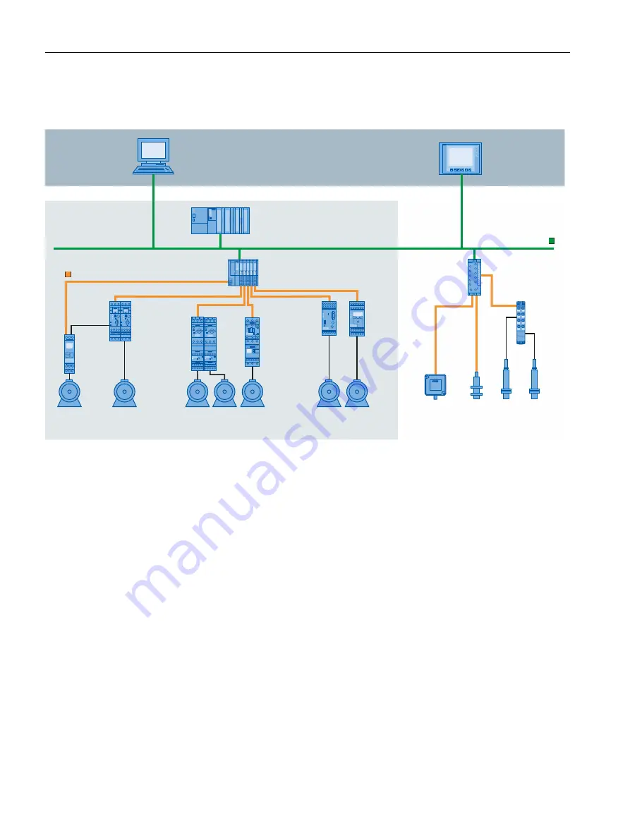
Example plant with IO-Link
The figure below shows an example of plant architecture with IO-Link.
7JTVBMJ[BUJPO
4*."5*$).*8JO$$
'JFMEJOTUBMMBUJPO
4*."5*$
&5FDP1/.-
XJUI*0-JOLNBTUFS
&5"-
*0-JOL*0
NPEVMF
4UBOEBSE
TFOTPST
3'*%TZTUFN
3'
3'*%TZTUFN
3'
4*3*64
SFMBZ
34
34
4*3*64
PWFSMPBE
SFMBZ3#
4*3*64DPOUBDUPS
35XJUI4*3*64
SFMBZ33
4*3*64MPBE
GFFEFST3"
XJUIGVODUJPO
NPEVMFT3"
4*3*64DPNQBDU
TUBSUFST3"
4*3*64
SFMBZ
6(
*0-JOL
&541
XJUI*0-JOLNBTUFS
44
BVUPNBUJPOTZTUFN
*OTUBMMBUJPOJODPOUSPMDBCJOFU
41$5
"DUVBUPST
130'*/&5
Figure 2-1 Plant architecture with IO-Link
The IO-Link master establishes the connection between the IO-Link devices and the
automation system. If the IO-Link master is a component of the I/O system, it is installed
either in the control cabinet or directly in the field as remote I/O in degree of protection
IP65/67. The IO-Link master communicates by means of various fieldbuses or product-specific
backplane buses. An IO-Link master can have multiple IO-Link ports (channels). An IO-Link
device can be connected (point-to-point communication) to each port.
Engineering
The IO-Link system is engineered parallel to the overall automation system and can be
embedded in it and intermeshed with it.
2.3
IO-Link interface
Introduction
The IO-Link is a serial, bidirectional point-to-point connection for signal transmission and
power distribution under any network, fieldbus or backplane bus.
10
IO-Link system
Function Manual, 07/2022, A5E31637677-AC
System overview
2.3 IO-Link interface


