Installation
8-7
TP 070 Equipment Manual
Release 03/00
8.2.1
Connect configuration computer
Connection configuration
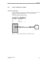
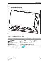
Figure 8-2 illustrates the connection of a configuration computer (PU or PC) to the
operating unit to download the project data. The connection displayed is
established by means of a PC-PPI cable.
The PC-PPI cable has the following settings:
Switch
Explanation
S1, S2, S3
38,4 kBaud
S4
NC
S5
DCE mode
COM
PC/PU 7xx
Operating unit
RS485
IF1B
RS232
Figure 8-2
Connection configuration diagram for configuration computer
Summary of Contents for SIMATIC HMI TP 070
Page 14: ...Functionality 2 2 TP 070 Equipment Manual Release03 00 ...
Page 18: ...Commissioning 3 4 TP 070 Equipment Manual Release03 00 ...
Page 34: ...System Settings 6 6 TP 070 Equipment Manual Release03 00 ...
Page 40: ...Communication Management for SIMATIC S7 7 6 TP 070 Equipment Manual Release03 00 ...
Page 54: ...Maintenance Upkeep 10 2 TP 070 Equipment Manual Release03 00 ...
Page 56: ...Operating System Update 11 2 TP 070 Equipment Manual Release03 00 ...
Page 57: ...APPENDIX A Technical Data B Interface Assignment C ESD Guidelines D SIMATIC HMI Documentation ...
Page 58: ...APPENDIX K 2 TP 070 Equipment Manual Release03 00 ...
Page 64: ...Technical Data A 6 TP 070 Equipment Manual Release03 00 ...
Page 66: ...Interface Assignment B 2 TP 070 Equipment Manual Release03 00 ...


