


Wall-mount enclosure 6DL2804-0xxxx
Hardware Installation Manual, 08/2009, A5E00378691N-02
23
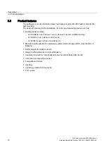
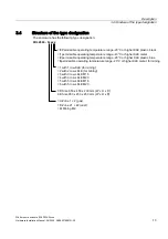
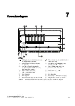
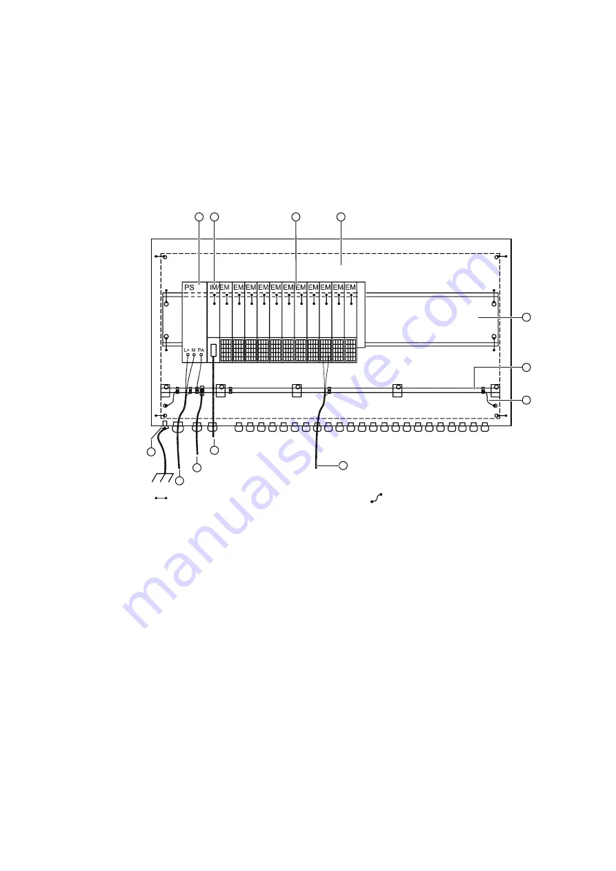
Connection diagram
7
Fixed galvanic electrical clamp or screw
connection inside enclosure
Cable connection can be disconnected
inside enclosure
①
Power supply terminal module with
componentry
⑦
Connection from the equipotential
bonding rail to the enclosure
②
IM / EM terminal module with IM
componentry (IM = interface module,
EM = electronic module)
⑧
Cable for signal lines shield on
equipotential bonding rail
③
EM / EM terminal module
(EM = electronic module)
⑨
PROFIBUS cable to IM
④
Mounting plate
⑩
Bonding cable
⑤
Mounting rail
⑪
Power supply (line to power supply)
⑥
Equipotential bonding rail with terminals
⑫
M6 grounding connection external
Figure 7-1
Fixed and detachable connections to ground and equipotential bonding rail