


Connection and commissioning
5.4 Commissioning
Air circuit breaker 3WL10
148
Manual, 11/2017, L1V30499596002-01
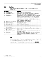
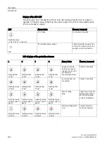
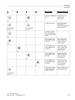
Accessories to be tested
Method
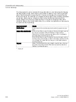
Closing coil (CC) with
actuator module COM ACT
1. Supply power to the ETU with the auxiliary voltage at the Breaker Connect module.
2. Switch on the contacts of the actuator module.
3. Charge the springs.
4. Choose item "Close CB" in the menu of ETUs of the 6-series.
Result: The circuit breaker closes correctly. The behavior and the signals of the
auxiliary switches are normal.
NOTE: The test can be conducted if voltage is applied to the protection enable and to
the coils.
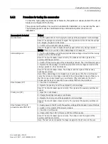
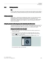
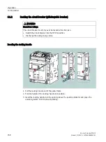
Interlocking for circuit breakers in
the open position (cylinder lock or
padlock)
1. Open the circuit breaker.
2. Hold the pushbutton for opening pressed or press the cover onto the mechanical
pushbutton while you hook in the padlock.
3. Turn the key and then remove it.
4. Attempt to close the circuit breaker.
Result: Both manual and electrical closing are prevented.
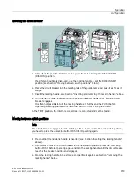
Auxiliary contacts of the circuit
breaker
1. Connect the auxiliary contacts to the corresponding signaling circuits.
2. Perform a few close and open operations on the circuit breaker.
Result: Signaling performed normally.
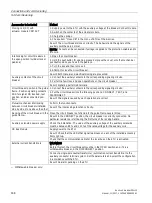
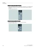
Circuit breaker position in the guide
frame. Position signaling contacts
PSS for signal: CB inserted, test
position, and disconnected posi-
tion
1)
1. Connect the auxiliary contacts to the corresponding signaling circuits.
2. Put the circuit breaker into the following positions: CONNECT, TEST, and
DISCONNECT.
Result: The signals caused by each operation are correct.
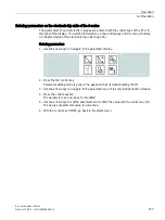
Mutual mechanical interlocking
between circuit breakers installed
side by side or one above the other
Perform the function tests.
Result: The interlockings function correctly.
Racking of the circuit breaker in the
guide frame
1)
Move the circuit breaker out of and into the guide frame several times.
Result: In the CONNECT position, the circuit breaker is correctly connected. No
particular resistance is felt during the first turns of the racking handle.
Auxiliary solenoids power supply
Check the installation: The value of the auxiliary voltage of the auxiliary solenoids
must be between 85 % and 110 % of the rated voltage for the auxiliary coils.
CB Bus Module
Supply power to the ETU.
Result: Check that the LEDs that signal readiness on each of the installed accessory
items light up.
Check that the communication cable for the local bus on the ETU is activated.
External current transformers
WARNING!
Before this test, the circuit breaker must be in the OPEN position and, if it is a
withdrawable breaker, in the DISCONNECT position.
Connect a single-pole neutral transformer / summation current transformer to the
auxiliary conductor terminal system. Set the parameters and select the configuration
in accordance with the ETU.
Result: No alarm pending on the ETU.
1)
Withdrawable breaker only:
Summary of Contents for SENTRON 3WL10
Page 1: ......
Page 2: ......
Page 8: ...Table of contents Air circuit breaker 3WL10 6 Manual 11 2017 L1V30499596002 01 ...
Page 170: ...Operation 6 3 Troubleshooting Air circuit breaker 3WL10 168 Manual 11 2017 L1V30499596002 01 ...
Page 180: ...Technical specifications Air circuit breaker 3WL10 178 Manual 11 2017 L1V30499596002 01 ...
Page 199: ...Air circuit breaker 3WL10 Manual 11 2017 L1V30499596002 01 197 Circuit diagrams 10 ...
Page 212: ...Circuit diagrams Air circuit breaker 3WL10 210 Manual 11 2017 L1V30499596002 01 ...
Page 233: ......
Page 234: ......


