


RUGGEDCOM WiN5100/WiN5200
User Guide
Chapter 4
Installation Procedure
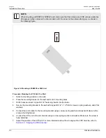
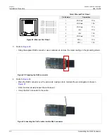
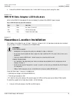
WiN1010 Data Adaptor LED Indicators
35
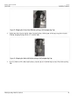
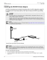
3. Connect the WiN1010 data adaptor to the 110 VAC/220 VAC power source using the cable.
Section 4.10.4
WiN1010 Data Adaptor LED Indicators
LEDs on the WiN1010 data adaptor front panel indicate the status of the WiN1010 power supply.
Table: WiN1010 Data Adaptor LED Indications
Name
Color
Description
PWR
Green
Input power is connected
LAN
Green
LAN link/activity display
WLNK
Green
Wireless link/activity display
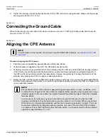
Section 4.11
Hazardous Location Installation
This equipment is suitable for use in Class 1, Division 2, Groups A, B, C, D hazardous locations when installed
using the Class 1, Division 2 installation kit (P/N MKIT0090).
WARNING!
EXPLOSION HAZARD
• Substitution of components may impair suitability for Class I, Division 2
• Do not disconnect equipment unless power has been switched off or the area is known to be non-
hazardous
• Use only Lambda DPP240-48-1 Power Supply in conjunction with the unit
RISQUE D’EXPLOSION
• La substitution decomposants peut rendre ce matériel inacceptable pour les emplacements de
Classe I, Division 2
• Avant de déconnecter l’equipment, couper le courant ou s’assurer que l’emplacement est désigné
non dangereux
• Utilisez l’unité uniquement avec une batterie de la marque Lamba DPP240-48-1
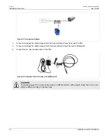
Contents of the Class 1, Division 2 Installation Kit:
• Lambda power supply unit (model DPP240-48-1)
• Y-Box Surge Suppression Unit
• DC cable for connection between the power supply unit (PSU) and the power-over-ethernet (PoE) injector
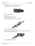
To install the equipment in a hazardous location, do the following:
1. Connect a DC cable between the PSU and PoE injector.
Summary of Contents for RUGGEDCOM WiN5100
Page 2: ...RUGGEDCOM WiN5100 WiN5200 User Guide ii ...
Page 8: ...RUGGEDCOM WiN5100 WiN5200 User Guide FCC Statement And Cautions viii ...
Page 26: ...RUGGEDCOM WiN5100 WiN5200 User Guide Chapter 2 Product Description LED Indicators 18 ...
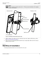
Page 28: ...RUGGEDCOM WiN5100 WiN5200 User Guide Chapter 3 Mounting Wall Mounting 20 ...
Page 106: ...RUGGEDCOM WiN5100 WiN5200 User Guide Appendix A WiN5100 WiN5200 Specifications 98 ...
Page 114: ...RUGGEDCOM WiN5100 WiN5200 User Guide Appendix D RUGGEDCOM CPE Warranty 106 ...