


Chapter 2
Product Description
RUGGEDCOM WiN5100/WiN5200
User Guide
16
WiN5200 Connectors
Section 2.3.5.3
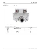
WiN5200 Connectors
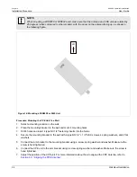
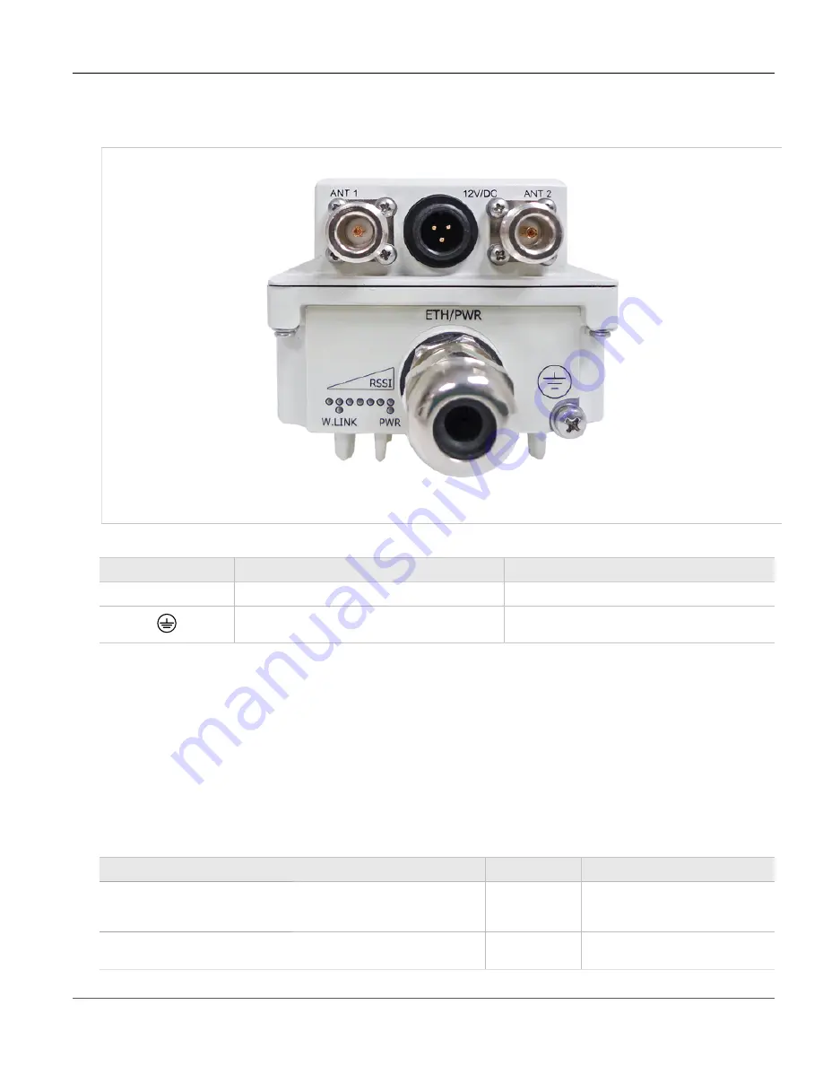
Figure 8: WiN5200 Connectors
Table: WiN5200 Connectors
Name
Description
Connector Type
ETH/PWR
Data and power from PoE injector
RJ-45
Ground
Grounding screw
Section 2.3.6
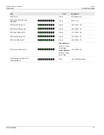
LED Indicators
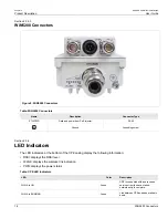
The LED indicators at the bottom of the CPE casing display the following information:
• RSSI: displays the RSSI level
• W.LNK: displays the wireless link indication
• PWR: displays the power status
Table: CPE LED Indicators
LED
Color
Description
WLNK is ON
Green
CPE is connected with and receives
services from the base station;
network entry is complete.
WLNK is BLINKING
Green
Link between CPE and base station is
down.
Summary of Contents for RUGGEDCOM WiN5100
Page 2: ...RUGGEDCOM WiN5100 WiN5200 User Guide ii ...
Page 8: ...RUGGEDCOM WiN5100 WiN5200 User Guide FCC Statement And Cautions viii ...
Page 26: ...RUGGEDCOM WiN5100 WiN5200 User Guide Chapter 2 Product Description LED Indicators 18 ...
Page 28: ...RUGGEDCOM WiN5100 WiN5200 User Guide Chapter 3 Mounting Wall Mounting 20 ...
Page 106: ...RUGGEDCOM WiN5100 WiN5200 User Guide Appendix A WiN5100 WiN5200 Specifications 98 ...
Page 114: ...RUGGEDCOM WiN5100 WiN5200 User Guide Appendix D RUGGEDCOM CPE Warranty 106 ...