background image

Chapter 5

Setup and Configuration

RUGGEDCOM ROX II

User Guide

382

Configuring a Broadcast Address

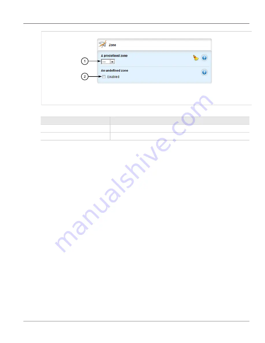
Figure 416: Zone Form

1.

 Predefined Zone List   


2.

 Undefined Zone Check Box

3. Configure the following parameter(s) as required:

Parameter

Description

predefined-zone

A pre-defined zone

undefined-zone

This is used in conjunction with hosts definitions.

4. Click 

Commit

 to save the changes or click 

Revert All

 to abort. A confirmation dialog box appears. Click 

OK

to proceed.

5. Click 

Exit Transaction

 or continue making changes.

Section 5.17.9.4

Configuring a Broadcast Address

To configure a broadcast address for an interface, do the following:
1. Change the mode to 

Edit Private

 or 

Edit Exclusive

.

2. Navigate to 

security

 » 

firewall

 » 

fwconfig

 » 

fwconfig

 » 

{firewall}

 » 

fwinterface{interface}

 » 

broadcast-

addr

, where 

{firewall}

 is the name of the firewall and 

{interface}

 is the name of the interface. The 

Broadcast

Address

 form appears.

Summary of Contents for RUGGEDCOM RX1510

Page 1: ...M ROX II v2 6 User Guide For RX1500 RX1501 RX1510 RX1511 RX1512 12 2014 Preface Introduction 1 Using ROX II 2 Device Management 3 System Administration 4 Setup and Configuration 5 Troubleshooting 6 RC1154 EN 02 ...

Page 2: ...ner of the mark on a world wide basis Other designations in this manual might be trademarks whose use by third parties for their own purposes would infringe the rights of the owner Open Source RUGGEDCOM ROX II is based on Linux Linux and RUGGEDCOM ROX II are made available under the terms of the GNU General Public License Version 2 0 http www gnu org licenses gpl 2 0 html Security Information Siem...

Page 3: ...ort 8 1 5 User Permissions 9 Chapter 2 Using ROX II 13 2 1 Connecting to ROX II 13 2 1 1 Connecting Directly 13 2 1 2 Connecting Through the Network 14 2 2 Default Usernames and Passwords 15 2 3 Logging In 15 2 4 Logging Out 16 2 5 Navigating the Interface 17 2 5 1 Menus 17 2 5 2 Modes 17 2 5 3 Edit Toolbar 19 2 5 4 Using the Navigation Menu 19 2 5 5 Icons 20 2 5 6 Common Controls 21 2 6 Using Net...

Page 4: ...ice 38 3 6 Restoring Factory Defaults 39 3 7 Decommissioning the Device 40 3 8 Managing Files 41 3 8 1 Uploading Files 41 3 8 2 Downloading Files 42 3 9 Managing Logs 42 3 9 1 Viewing Logs 43 3 9 2 Deleting Logs 44 3 9 3 Managing Diagnostic Logs 45 3 9 3 1 Enabling Disabling the Developer s Log 46 3 9 3 2 Enabling Disabling the SNMP Log 46 3 9 3 3 Enabling Disabling the NETCONF Summary Log 47 3 9 ...

Page 5: ... 68 3 12 3 Upgrading an Application 69 3 12 4 Uninstalling an Application 70 3 12 5 Managing Application Repositories 71 3 12 5 1 Viewing a List of Repositories 71 3 12 5 2 Checking the Repository Connection 72 3 12 5 3 Adding a Repository 73 3 12 5 4 Deleting a Repository 74 3 13 Managing Feature Keys 75 3 14 Installing and Backing Up Files 75 3 14 1 Installing Files 76 3 14 2 Backing Up Files 77...

Page 6: ...figuring a Routable Ethernet Port 108 3 20 Managing Serial Ports 111 3 20 1 Viewing a List of Serial Ports 111 3 20 2 Viewing Serial Port Statistics 112 3 20 3 Viewing Transport Connection Statistics 113 3 20 4 Viewing DNP Device Table Statistics 115 3 20 5 Clearing Serial Port Statistics 115 3 20 6 Configuring a Serial Port 116 3 20 7 Restarting the Serial Server 118 3 20 8 Resetting a Serial Por...

Page 7: ...ewing the HSPA Network Status for Cellular Modems 143 3 23 5 Viewing the CDMA Network Status for Cellular Modems 145 3 23 6 Configuring a Cellular Modem Interface 146 3 23 7 Activating a Cellular Modem Account 147 3 23 7 1 Activating a Cellular Modem Account Over the Air 147 3 23 7 2 Activating a Cellular Modem Account Manually 148 3 23 8 Resetting the Cellular Modem 150 3 23 9 Running AT Commands...

Page 8: ...79 3 26 1 1 Viewing a List of Domain Names 180 3 26 1 2 Adding a Domain Name 180 3 26 1 3 Deleting a Domain Name 181 3 26 2 Managing Domain Name Servers 182 3 26 2 1 Viewing a List of Domain Name Servers 182 3 26 2 2 Adding a Domain Name Server 182 3 26 2 3 Deleting a Domain Name Server 183 Chapter 4 System Administration 185 4 1 Configuring the System Name and Location 185 4 2 Configuring the Hos...

Page 9: ...es 214 4 8 2 Configuring RADIUS Authentication for PPP Services 215 4 8 3 Configuring RADIUS Authentication for Switched Ethernet Ports 217 4 9 Managing Users 218 4 9 1 Viewing a List of Users 219 4 9 2 Adding a User 220 4 9 3 Deleting a User 221 4 9 4 Monitoring Users 221 4 9 4 1 Kicking Users from the Network 222 4 9 4 2 Sending Messages to Users 223 4 10 Managing Passwords and Passphrases 224 4...

Page 10: ...ng SNMP Communities 263 5 11 5 1 Viewing a List of SNMP Communities 263 5 11 5 2 Adding an SNMP Community 263 5 11 5 3 Deleting an SNMP Community 264 5 11 6 Managing SNMP Target Addresses 265 5 11 6 1 Viewing a List of SNMP Target Addresses 265 5 11 6 2 Adding an SNMP Target Address 266 5 11 6 3 Deleting an SNMP Target Address 269 5 11 7 Managing SNMP Users 269 5 11 7 1 Viewing a List of SNMP User...

Page 11: ...ast Address 292 5 12 13 Managing Server Keys 293 5 12 13 1 Viewing a List of Server Keys 293 5 12 13 2 Adding a Server Key 294 5 12 13 3 Deleting a Server Key 295 5 12 14 Managing Server Restrictions 295 5 12 14 1 Viewing a List of Server Restrictions 296 5 12 14 2 Adding a Server Restriction 296 5 12 14 3 Deleting a Server Restriction 298 5 13 Managing Cellular Modem Profiles 298 5 13 1 Managing ...

Page 12: ...324 5 15 7 3 Configuring Subnet Options 325 5 15 7 4 Configuring a Subnet Client 327 5 15 7 5 Deleting a Subnet 330 5 15 8 Managing Custom Client Options for Subnets 330 5 15 8 1 Viewing a List of Custom Client Options 331 5 15 8 2 Adding a Custom Client Option 331 5 15 8 3 Deleting a Custom Client Option 332 5 15 9 Managing Hosts 333 5 15 9 1 Viewing a List of Hosts 333 5 15 9 2 Adding a Host 334...

Page 13: ...m an IP Pool 357 5 15 16 Managing Option 82 Classes for IP Pools 358 5 15 16 1 Viewing a List of Option 82 Classes for IP Pools 358 5 15 16 2 Adding an Option 82 Class to an IP Pool 359 5 15 16 3 Deleting an Option 82 Class From an IP Pool 360 5 16 Managing Port Mirroring 361 5 16 1 Configuring Port Mirroring 362 5 16 2 Managing Egress Source Ports 362 5 16 2 1 Viewing a List of Egress Source Port...

Page 14: ...es 387 5 17 11 1 Viewing a List of Policies 388 5 17 11 2 Adding a Policy 388 5 17 11 3 Configuring the Source Zone 390 5 17 11 4 Configuring the Destination Zone 391 5 17 11 5 Deleting a Policy 391 5 17 12 Managing Network Address Translation Settings 392 5 17 12 1 Viewing a List of NAT Settings 392 5 17 12 2 Adding a NAT Setting 393 5 17 12 3 Deleting a NAT Setting 395 5 17 13 Managing Masquerad...

Page 15: ... an SPF Calculation Interval 424 5 18 8 Managing the Lifetime of LSPs 425 5 18 8 1 Viewing a List of LSP Lifetime Intervals 425 5 18 8 2 Adding an LSP Lifetime Interval 426 5 18 8 3 Deleting an LSP Lifetime Interval 427 5 18 9 Managing LSP Refresh Intervals 428 5 18 9 1 Viewing a List of LSP Refresh Intervals 428 5 18 9 2 Adding an LSP Refresh Interval 428 5 18 9 3 Deleting an LSP Refresh Interval...

Page 16: ...2 Viewing a List of Prefix Entries 453 5 19 5 3 Adding a Prefix List 453 5 19 5 4 Adding a Prefix Entry 454 5 19 5 5 Deleting a Prefix List 456 5 19 5 6 Deleting a Prefix Entry 456 5 19 6 Managing Autonomous System Paths and Entries 457 5 19 6 1 Viewing a List of Autonomous System Paths 457 5 19 6 2 Viewing a List of Autonomous System Path Entries 458 5 19 6 3 Adding an Autonomous System Path Filt...

Page 17: ...ng a Prefix List 484 5 20 3 6 Deleting a Prefix Entry 485 5 20 4 Managing Networks 485 5 20 4 1 Configuring a Network 486 5 20 4 2 Tracking Commands 486 5 20 5 Managing Network IP Address 487 5 20 5 1 Viewing a List of Network IP Addresses 487 5 20 5 2 Adding a Network IP Address 488 5 20 5 3 Deleting a Network IP Address 488 5 20 6 Managing Network Interfaces 489 5 20 6 1 Viewing a List of Networ...

Page 18: ...ewing a List of Prefix Entries 513 5 21 4 3 Adding a Prefix List 513 5 21 4 4 Adding a Prefix Entry 514 5 21 4 5 Deleting a Prefix List 516 5 21 4 6 Deleting a Prefix Entry 517 5 21 5 Managing Areas 517 5 21 5 1 Viewing a List of Areas 518 5 21 5 2 Adding an Area 518 5 21 5 3 Deleting an Area 519 5 21 6 Managing Route Maps 520 5 21 6 1 Viewing a List of Route Map Filters 520 5 21 6 2 Viewing a Lis...

Page 19: ... Static Routes 543 5 22 6 3 Adding a Gateway for an IPv4 Static Route 543 5 22 6 4 Deleting a Gateway for an IPv4 Static Route 544 5 22 7 Managing Interfaces for Static Routes 545 5 22 7 1 Configuring Interfaces for IPv6 Static Routes 545 5 22 7 2 Viewing a List of Interfaces for IPv4 Static Routes 546 5 22 7 3 Adding an Interface for an IPv4 Static Route 546 5 22 7 4 Deleting an Interface for an ...

Page 20: ... 25 5 Managing the Static Multicast Group Table 574 5 25 5 1 Viewing a List of Static Multicast Group Entries 574 5 25 5 2 Adding a Static Multicast Group Entry 575 5 25 5 3 Deleting a Static Multicast Group Entry 575 5 25 6 Managing Egress Ports for Multicast Groups 576 5 25 6 1 Viewing a List of Egress Ports 576 5 25 6 2 Adding an Egress Port 577 5 25 6 3 Deleting an Egress Port 577 5 25 7 Viewi...

Page 21: ...e Link Failover Log 601 5 27 2 Viewing the Link Failover Status 601 5 27 3 Managing Link Failover Parameters 602 5 27 3 1 Viewing a List of Link Failover Parameters 603 5 27 3 2 Adding a Link Failover Parameter 603 5 27 3 3 Deleting a Link Failover Parameter 605 5 27 4 Managing Link Failover Backup Interfaces 605 5 27 4 1 Viewing a List of Link Failover Backup Interfaces 606 5 27 4 2 Adding a Link...

Page 22: ...8 7 3 Deleting an IKE Algorithm 627 5 28 8 Managing the Encapsulated Security Payload ESP Protocol 628 5 28 8 1 Configuring ESP Encryption 628 5 28 8 2 Viewing a List of ESP Algorithms 629 5 28 8 3 Adding ESP Algorithms 630 5 28 8 4 Deleting ESP Algorithms 630 5 28 9 Configuring the Connection Ends 631 5 28 10 Managing Private Subnets 634 5 28 10 1 Configuring Private Subnets for Connection Ends 6...

Page 23: ...29 10 Managing Ethernet Types for Generic Tunnels 660 5 29 10 1 Viewing a List of Ethernet Types 661 5 29 10 2 Adding an Ethernet Type 661 5 29 10 3 Deleting an Ethernet Type 662 5 30 Managing Generic Routing Encapsulation Tunnels 662 5 30 1 Viewing Statistics for GRE Tunnels 663 5 30 2 Viewing a List of GRE Tunnels 664 5 30 3 Adding a GRE Tunnel 664 5 30 4 Deleting a GRE Tunnel 667 5 31 Managing ...

Page 24: ...g Options 689 5 33 4 Managing Static MAC Addresses 690 5 33 4 1 Viewing a List of Static MAC Addresses 691 5 33 4 2 Adding a Static MAC Address 691 5 33 4 3 Deleting a Static MAC Address 693 5 34 Managing Spanning Tree Protocol 693 5 34 1 RSTP Operation 694 5 34 1 1 RSTP States and Roles 694 5 34 1 2 Edge Ports 696 5 34 1 3 Point to Point and Multipoint Links 696 5 34 1 4 Path and Port Costs 696 5...

Page 25: ... Untagged Frames 725 5 35 1 2 Native VLAN 725 5 35 1 3 Edge and Trunk Port Types 725 5 35 1 4 Ingress and Egress Rules 726 5 35 1 5 Forbidden Ports List 727 5 35 1 6 VLAN Aware Mode of Operation 727 5 35 1 7 GARP VLAN Registration Protocol GVRP 727 5 35 1 8 PVLAN Edge 729 5 35 1 9 VLAN Advantages 729 5 35 2 Configuring VLANs for Switch Ethernet Ports 731 5 35 3 Configuring the Internal VLAN Range ...

Page 26: ...g Traffic Control Interfaces 758 5 37 2 1 Viewing a List of Traffic Control Interfaces 758 5 37 2 2 Adding a Traffic Control Interface 758 5 37 2 3 Deleting a Traffic Control Interface 760 5 37 3 Managing Traffic Control Priorities 761 5 37 3 1 Viewing a List of Traffic Control Priorities 761 5 37 3 2 Adding a Traffic Control Priority 762 5 37 3 3 Deleting a Traffic Control Priority 764 5 37 4 Man...

Page 27: ...38 6 Managing IPv6 Addresses 800 5 38 6 1 Viewing a List of IPv6 Addresses 800 5 38 6 2 Adding an IPv6 Address 800 5 38 6 3 Deleting an IPv6 Address 801 5 39 Managing MPLS 801 5 39 1 Viewing the Status of IP Binding 802 5 39 2 Viewing the Status of the Forwarding Table 803 5 39 3 Enabling Disabling MPLS Routing 803 5 39 4 Managing the MPLS Interfaces 804 5 39 4 1 Viewing the Status of MPLS Interfa...

Page 28: ...4 Viewing the Status of the LDP Neighbor Connection Information 815 5 39 7 5 Viewing the Status of the LDP Neighbor Discovery Information 815 5 39 7 6 Configuring LDP 816 5 39 7 7 Configuring Neighbor Discovery 817 5 39 7 8 Viewing a List of LDP Interfaces 818 5 39 7 9 Enabling Disabling an LDP Interface 818 Chapter 6 Troubleshooting 821 6 1 Feature Keys 821 6 2 Ethernet Ports 821 6 3 Multicast Fi...

Page 29: ...ANGER alerts describe imminently hazardous situations that if not avoided will result in death or serious injury WARNING WARNING alerts describe hazardous situations that if not avoided may result in serious injury and or equipment damage CAUTION CAUTION alerts describe hazardous situations that if not avoided may result in equipment damage IMPORTANT IMPORTANT alerts provide important information ...

Page 30: ...andard courses on networking Ethernet switches and routers to on site customized courses tailored to the customer s needs experience and application Siemens Educational Services team thrives on providing our customers with the essential practical skills to make sure users have the right knowledge and expertise to understand the various technologies associated with critical communications network i...

Page 31: ...Pages default aspx Mobile App Install the Industry Online Support app by Siemens AG on any Android Apple iOS or Windows mobile device and be able to Access Siemens extensive library of support documentation including FAQs manuals and much more Submit SRs or check on the status of an existing SR Find and contact a local contact person Ask questions or share knowledge with fellow Siemens customers a...

Page 32: ...RUGGEDCOM ROX II User Guide Preface Customer Support xxxii ...

Page 33: ...ailable in ROX II and their benefits Cyber Security Cyber security is an urgent issue in many industries where advanced automation and communications networks play a crucial role in mission critical applications and where high reliability is of paramount importance Key ROX II features that address security issues at the local area network level include Passwords Multi level user passwords secures ...

Page 34: ...er SNMP versions ROX II also supports numerous standard MIBs Management Information Base allowing for easy integration with any Network Management System NMS A feature of SNMP supported by ROX II is the ability to generate traps upon system events RUGGEDCOM NMS the Siemens management solution can record traps from multiple devices providing a powerful network troubleshooting tool It also provides ...

Page 35: ...f critical alarms allowing an external controller to react if desired HTML Web Browser User Interface ROX II provides a simple intuitive user interface for configuration and monitoring via a standard graphical Web browser or via a standard telcom user interface All system parameters include detailed online help to make setup a breeze ROX II presents a common look and feel and standardized configur...

Page 36: ...on Protection against Brute Force Attacks BFAs is standard in ROX II If an external host fails to log in to the CLI NETCONF or Web interfaces after a fixed number of attempts the host s IP address will be blocked for a period of time That period of time will increase if the host continues to fail on subsequent attempts Secure Software Upgrade ADD CONTENT USB Mass Storage Use a removable USB Mass S...

Page 37: ...placed on a USB Mass Storage device which allows them to be moved to other devices when needed NOTE Each feature key is signed with the serial number of the device it is intended to be used in Feature keys can be used in other ROX II devices but a low level alarm will be generated indicating a hardware mismatch Feature keys include the following features Feature Key Feature Layer 2 Standard Editio...

Page 38: ... it inaccessible CAUTION Accessibility hazard risk of data loss Do not misplace the passwords for the device If both the maintenance and boot passwords are misplaced the device must be returned to Siemens Canada Ltd for repair This service is not covered under warranty Depending on the action that must be taken to regain access to the device data may be lost Replace the default passwords for all u...

Page 39: ...ation files are provided in either NETCONF or CLI format for ease of use Make sure configuration files are properly protected when they exist outside of the device For instance encrypt the files store them in a secure place and do not transfer them via insecure communication channels It is highly recommended that critical applications be limited to private networks or at least be accessible only t...

Page 40: ...ss Authorized Denotes whether the ports services are authenticated during access Services Port Number Port Open Port Default Access Authorized SSH TCP 22 Open if configured with login Open Yes SSH Service Mode TCP 222 Open Open Yes NETCONF TCP 830 Open if configured with login Open Yes SFTP TCP 2222 Open if configured with login Closed Yes HTTP TCP 80 Open if configured with login Open N A NTP UDP...

Page 41: ...e U can modify existing parameter Access Commands Paths Permitted Administrator Operator Guest Notes config private exclusive no confirm Allowed Allowed No admin software upgrade R U No No admin rox imaging R U No No admin authentication R U No No admin authentication password complexity R U R No admin logging C R U No No admin alarms status R R No Administrator and operator can see status of acti...

Page 42: ...E R U No No admin delete all ssh known hosts action E E No admin delete logs action E No No admin delete ssh known host action E E No admin full configuration load action E U No No admin full configuration save action E U No No admin install files action E U No No admin reboot action E E No admin restore factory defaults action E U No No admin set system clock action E U E No admin shutdown action...

Page 43: ...s C R U C R U R services time ntp key C R U No No tunnel C R U C R U R tunnel ipsec C R U No No ip C R U C R U R mpls C R U C R U R mpls interface mpls R U R U R mpls ldp interface ldp R U R U R switch C R U C R U R switch vlans all vlans C R U C R U R switch port security R U No No qos C R U C R U R global C R U No No hints E E E monitor E E No mpls ping E E No mpls traceroute E E No ping E E No ...

Page 44: ...RUGGEDCOM ROX II User Guide Chapter 1 Introduction User Permissions 12 ...

Page 45: ...ace Section 2 1 Connecting to ROX II The following describes the various methods for connecting the device Section 2 1 1 Connecting Directly Section 2 1 2 Connecting Through the Network Section 2 1 1 Connecting Directly ROX II can be accessed through a direct serial or Ethernet connection Using the RS232 Serial Console Port To establish a serial connection to the device refer to the CLI User Guide...

Page 46: ... port The login prompt appears Using username admin admin 192 168 0 2 s password 4 Log in to ROX II For more information about logging in to ROX II refer to Section 2 3 Logging In Section 2 1 2 Connecting Through the Network To connect to ROX II through the network do the following 1 On the computer being used to connect to the device configure the Ethernet port to use an IP address falling within...

Page 47: ...92 168 0 1 and press Enter Once the connection is established the login screen for the Web interface appears For more information about logging in to ROX II refer to Section 2 3 Logging In Section 2 2 Default Usernames and Passwords The following default passwords are pre configured on the device for each access mode CAUTION Security hazard risk of unauthorized access and or exploitation To preven...

Page 48: ...r accounts refer to Section 4 9 2 Adding a User 2 In the Username field type the user name NOTE If a unique password passphrase has not been configured use the factory default password For more information refer to Section 2 2 Default Usernames and Passwords 3 In the Password field type the password associated with the username 4 Click Submit The main ROX II menu appears Section 2 4 Logging Out To...

Page 49: ...enus The toolbar at the top of the ROX II interface allows access to two separate menus Configure Running and Tools 1 2 Figure 4 Toolbar 1 Configure Running Menu 2 Tools Menu Configure Running Click the Configure Running link to access the main ROX II interface Tools Click the Tools link to access various tools such as a built in CLI system network logs network utilities and administrative control...

Page 50: ...n session the user in the private configuration session cannot commit their changes until the other user ends their session Edit Exclusive Mode Edit Exclusive mode is similar to Edit Private mode except all other users are blocked from committing their changes until the user using Edit Exclusive mode exits Only one Operator or Admin user can use Edit Exclusive mode at a time per device In Edit Exc...

Page 51: ...ion Changes Present a summary of all pending changes Validate Automatically check the validity of pending changes Revert All Abort all pending changes Commit Commit all pending changes Rollback Present a list of change sets made to date with an option to revert a selected set of changes Exit Transaction Exit from configuration editing mode All pending changes will be discarded Section 2 5 4 Using ...

Page 52: ... Home arrow The following icons appear in the navigation menu Folder icons represent nodes under which forms or additional nodes are located Click on a node to open the next menu level and display any associated tables or forms A blue folder icon represents a configuration node whereas a green folder icon represents a status node that provides up to date information about the device and the networ...

Page 53: ...tion Type Key setting Global setting Operational data Configuration data Input data Action Section 2 5 6 Common Controls The following are common controls that can be found in the ROX II Web interface Check Box Click a check box to select or enable an option Clear the check box to deselect or disable the option List Select a value from a list ...

Page 54: ...re used in combination for complex parameter configurations For example the following parameter combines a list box and button allowing users to enter multiple values Users enter a single value in the box and then click the Add button to add the value to the list 2 3 1 Figure 9 Example Complex Control 1 List 2 Box 3 Button Section 2 6 Using Network Utilities The following sections describe how to ...

Page 55: ...Tools Menu 2 Accessories Menu 3 Ping Menu 4 Ping6 Menu 2 Depending on the host s IP address click Ping if the host has an IPv4 address or Ping6 if the host has an IPv6 address The Ping screen appears 3 1 2 4 Figure 11 Ping Screen 1 New Button 2 Stop Button 3 Current Ping Session List 4 Result Window 3 Click New The Specify Host dialog box appears ...

Page 56: ...the Address box and click OK The results of the ping action are displayed in the Ping Result Window Section 2 6 2 Dumping Raw Data to a Terminal or File Tcpdump is a packet analyzer for TCP IP and other packets It can be used to dump raw data to a terminal or file To dump raw data to a terminal or file do the following 1 Select the Tools menu and click Accessories 2 Click Tcpdump The Tcpdump scree...

Page 57: ...ackets Captured set the maximum number of packets to capture 5 Under Maximum Capture Time set the maximum time to capture packets 6 If necessary select Lookup Addresses to display the source IP for each packet 7 If necessary select Display Link Level Header to display the link level header information for each packet 8 If necessary select Perform HEX ASCII Dump to convert the data to hexadecimal o...

Page 58: ...ut Check Box 3 Lookup Address Check Box 4 Use ICMP Instead of UDP Check Box 5 Trace It Button 6 How Many Hops Box 7 Packet Length Box 8 Interface List 9 Result Window 3 Under Hostname type the name or IP address of the host 4 If necessary select Verbose Output to make the trace results more detailed 5 If necessary select Lookup Address to display the source IP address 6 If necessary select Use ICM...

Page 59: ...Ping Screen 1 Remote IP Address Prefix Box 2 How Many Pings Box 3 Start Button 4 Result Window 3 Type the IPv4 address in the Remote IP Address Prefix box 4 Type the number of pings in the How Many Pings box and click Start The results of the ping action are displayed in the Result Window Section 2 6 5 Tracing the Route of an IPv4 Address Using MPLS Protocols To trace the route of an IPv4 adress u...

Page 60: ...Window 3 Type the IPv4 address in the Remote IP Address Prefix box and click Start The results of the trace are displayed in the Result Window Section 2 7 Using the Command Line Interface The Web interface includes a built in Command Line Interface CLI To access the Command Line Interface CLI from within the Web interface select the Tools menu and click CLI The CLI screen appears ...

Page 61: ... 2 Using ROX II Using the Command Line Interface 29 2 3 4 1 Figure 17 CLI Screen 1 CLI Window 2 Start Button 3 Stop Button 4 Paste Button For more information about how to use the Command Line Interface refer to the RX1500 CLI User Guide ...

Page 62: ...RUGGEDCOM ROX II User Guide Chapter 2 Using ROX II Using the Command Line Interface 30 ...

Page 63: ... Decommissioning the Device Section 3 8 Managing Files Section 3 9 Managing Logs Section 3 10 Managing the Software Configuration Section 3 11 Upgrading Downgrading the ROX II Software Section 3 12 Managing ROX II Applications Section 3 13 Managing Feature Keys Section 3 14 Installing and Backing Up Files Section 3 15 Managing Fixed Modules Section 3 16 Managing Line Modules Section 3 17 Managing ...

Page 64: ...Form Section 3 2 Viewing Chassis Information and Status The following sections describe how to view the routing status for various routing protocols and related statistics Section 3 2 1 Viewing the Slot Hardware Section 3 2 2 Viewing Module Information Section 3 2 3 Viewing Flash Card Storage Utilization Section 3 2 4 Viewing CPU RAM Utilization Section 3 2 5 Viewing the Slot Status Section 3 2 6 ...

Page 65: ...al Number The installed module s unique serial number Section 3 2 2 Viewing Module Information To view information about the modules installed in the device navigate to chassis info The Slot Identification table appears Figure 20 Slot Identification Table This table provides the following information Parameter Description slot Synopsis pm1 pm2 main sm lm1 lm2 lm3 lm4 lm5 lm6 cm em trnk The slot na...

Page 66: ... Partition Usage This table provides the following information Parameter Description Storage Name The type of storage Total Capacity KiB The total capacity of the flash storage in KB Current Partition The partition ROX is currently running on and booted from Current Partition Capacity KiB The capacity of the current partition in KB Secondary Partition Capacity KiB The capacity of the secondary par...

Page 67: ...used in percent on the installed module RAM Low The lowest proportion of unused memory RAM in percent recorded for the installed module since start up Section 3 2 5 Viewing the Slot Status To view the overall status of each slot navigate to chassis status The Slot Status table appears Figure 23 Slot Status Table This table provides the following information Parameter Description slot Synopsis pm1 ...

Page 68: ...his table provides the following information Parameter Description slot Synopsis pm1 pm2 main sm lm1 lm2 lm3 lm4 lm5 lm6 cm em trnk The slot name as marked on the silkscreen across the top of the chassis Detected Module The installed module s type specifier Temperature degrees C The temperature in degrees C of the installed module If multiple temperature sensors are present on the board the maximu...

Page 69: ... the chassis MOV Protection Synopsis na working damaged The state of the MOV protection circuit PM Temperature C The temperature Celsius inside the power module PM Current mA The current mA sourced by the power module PM Voltage mV The voltage mV sourced by the power module Section 3 3 Viewing the Parts List To view a list of parts installed in the device navigate to chassis part list The Module D...

Page 70: ...e devices shuts down and provides a time out period during which power can be disconnected from the device The default time out period is 300 seconds five minutes At the end of the time out period the device reboots and restarts NOTE If wiring hinders the process of disconnecting power from the device the power module s can be removed instead 1 Navigate to admin and click shutdown in the menu The ...

Page 71: ...actory Defaults To restore the factory defaults for the device do the following 1 Navigate to admin and click restore factory defaults in the menu The Restore Factory Defaults and Trigger Action forms appear 1 2 3 4 Figure 29 Restore Factory Defaults Form 1 Delete Logs Check Box 2 Default Both Partitions Check Box 3 Delete Saved Configurations Check Box 4 Shutdown Check Box ...

Page 72: ...tion 3 7 Decommissioning the Device Before taking the device out of service either permanently or for maintenance by a third party make sure the device has been fully decommissioned This includes removing any sensitive proprietary information To decommission the device do the following 1 Obtain a copy of the ROX II firmware currently installed on the device For more information contact Siemens Cus...

Page 73: ...Uploading Files Section 3 8 2 Downloading Files Section 3 8 1 Uploading Files The following file types can be uploaded to the device configuration files feature keys To upload a file to the device do the following 1 Select the Tools menu and click Upload The Upload screen appears 1 3 2 4 Figure 31 Upload Screen 1 File Type List 2 File Box 3 Browse Button 4 Send Button 2 Under Choose file type sele...

Page 74: ...listed 3 Click the filename Depending on the browser a save dialog box appears 4 Open the file or save it to an appropriate location Section 3 9 Managing Logs ROX II maintains various logs to record information about important events Each log falls into one of the following log types Security Event Logs Information related to the following security events are logged by ROX II NOTE Passwords can be...

Page 75: ...es all err level and above logs written to the daemon facility messages catches all info notice and warn level logs for all facilities except auth authpriv cron daemon mail and news A selector setup using the following facilities at level info and up is recommended daemon user kern syslog Diagnostic Logs Diagnostic logs record system information for the purposes of troubleshooting The following se...

Page 76: ...ntrol the content of the log do the following Enter a number in the Last box to control the number of lines displayed Enter a number word or phrase in the Text Filter box to show only lines that contain the specified text Click Fresh to filter the content of the log Section 3 9 2 Deleting Logs To delete all logs stored on the device do the following 1 Navigate to admin and click delete logs in the...

Page 77: ...XPATH Trace Log var log xpath trace log WebUI Trace Log var log webui trace log CAUTION Configuration hazard risk of reduced performance Enabling diagnostic logging will significantly affect the performance of ROX II Only enable diagnostic logging when directed by Siemens The following sections describe how to configure and manage diagnostic logs Section 3 9 3 1 Enabling Disabling the Developer s ...

Page 78: ...ge the mode to Edit Private or Edit Exclusive 2 Navigate to admin logging diagnostics The Developer s Log form appears Figure 35 Developer s Log Form 1 Enabled Check Box 2 Log Level List 3 Configure the following parameter s as required Parameter Description Enabled Default false Enables Disables developer logging to the confd dev log log level Synopsis error info trace Default info Sets the verbo...

Page 79: ...t false Enables Disables SNMP logging to the snmp trace log 4 Click Commit to save the changes or click Revert All to abort A confirmation dialog box appears Click OK to proceed 5 Click Exit Transaction or continue making changes Section 3 9 3 3 Enabling Disabling the NETCONF Summary Log The NETCONF summary log briefly records NETCONF protocol transactions and in particular those which completed s...

Page 80: ...ing changes Section 3 9 3 4 Enabling Disabling the NETCONF Trace Log The NETCONF trace log details all NETCONF protocol transactions including successful and failed transactions CAUTION Configuration hazard risk of reduced performance Enabling diagnostic logging will significantly affect the performance of ROX II Only enable diagnostic logging when directed by Siemens To enable or disable the NETC...

Page 81: ...AUTION Configuration hazard risk of reduced performance Enabling diagnostic logging will significantly affect the performance of ROX II Only enable diagnostic logging when directed by Siemens To enable or disable the XPATH Trace log do the following 1 Change the mode to Edit Private or Edit Exclusive 2 Navigate to admin logging diagnostics The XPATH Trace Log form appears Figure 39 XPATH Trace Log...

Page 82: ...Figure 40 WebUI Trace Log Form 1 Enabled Check Box 3 Configure the following parameter s as required Parameter Description Enabled Default false Enables disables WebUI Trace logging to the webui trace log 4 Click Commit to save the changes or click Revert All to abort A confirmation dialog box appears Click OK to proceed 5 Click Exit Transaction or continue making changes Section 3 9 4 Managing Re...

Page 83: ...ion 3 9 4 2 Adding a Remote Server Section 3 9 4 2 Adding a Remote Server To add a remote server do the following 1 Change the mode to Edit Private or Edit Exclusive 2 Navigate to admin logging server and click Add server The Key Settings form appears Figure 42 Key Settings Form 1 Server IP Address Box 2 Add Button 3 Configure the following parameter s as required Parameter Description Server IP A...

Page 84: ...mmit to save the changes or click Revert All to abort A confirmation dialog box appears Click OK to proceed 8 Click Exit Transaction or continue making changes Section 3 9 4 3 Deleting a Remote Server To delete a remote server do the following 1 Change the mode to Edit Private or Edit Exclusive 2 Navigate to admin logging server The Remote Server table appears 2 3 1 Figure 44 Remote Server Table 1...

Page 85: ...erver Selectors To view a list of remote server selectors navigate to admin logging server address selector where address is the IP address of the remote server If remote server selectors have been configured the Remote Server Selector table appears Figure 45 Remote Server Selector Table If no remote server selectors have been configured add selectors as needed For more information refer to Sectio...

Page 86: ... Description name The log selector identifier Enter an integer greater than 0 up to 8 selectors can be added The log selector determines which subsystem messages are included in the log 5 Click Add The Remote Server Selector form appears Figure 47 Remote Server Selector Form 1 Negate Check Box 2 Comparison List 3 Level List 4 Facility List 5 Add Button 6 Configure the following parameter s as requ...

Page 87: ...son field includes debug and all higher severity messages in the log level Synopsis emerg alert crit err warning notice info debug none all Default all The base message severity level to include in the log all includes all messages none excludes all messages Other levels are listed in order of increasing severity facility list Synopsis auth authpriv cron daemon ftp kern lpr mail news security sysl...

Page 88: ...ion or continue making changes Section 3 10 Managing the Software Configuration Configuration parameters for ROX II can be saved on the device and loaded in the future The following sections describe how to save and load the ROX II software configuration Section 3 10 1 Saving the Configuration Section 3 10 2 Loading a Configuration Section 3 10 1 Saving the Configuration To save the configuration ...

Page 89: ...ll Configuration Save form configure the following parameters Parameter Description format Synopsis cli Save full configuration to a file file name 3 On the Trigger Action form click Perform Section 3 10 2 Loading a Configuration To load a configuration file for ROX II do the following 1 Navigate to admin and click full configuration load in the menu The Load Full Configuration and Trigger Action ...

Page 90: ...s Parameter Description format Synopsis cli Load a full configuration from a file file name 3 On the Trigger Action form click Perform 4 Click Commit to save the changes or click Revert All to abort A confirmation dialog box appears Click OK to proceed Section 3 11 Upgrading Downgrading the ROX II Software The following sections describe how to upgrade and downgrade the ROX II software Section 3 1...

Page 91: ... Upgrade Settings form appears Figure 53 Upgrade Settings Form 1 Upgrade Server URL Box 2 Target ROX Version Button 3 Configure the following parameter s as required Parameter Description Upgrade Server URL The URL for the upgrade server or file system Supported URIs are http https and ftp To upgrade from a USB device the URL format is usb usb device name path to repository and only one single par...

Page 92: ...via HTTPS the server s public key must be signed by a trusted Certificate Authority CA A list of recognized CA s is available under etc ssl certs which can be accessed via the CLI For more information about viewing the contents of a file via the CLI refer to the RUGGEDCOM ROX II v2 6 CLI User Guide NOTE Each device should be configured to upgrade at different times to minimize impact on the networ...

Page 93: ...3 11 3 Upgrading the ROX II Software ROX II software upgrades are managed between two partitions One partition is always active while the other is always inactive Software upgrades are always applied to the inactive partition This allows the active partition to function normally during a software upgrade and for users to roll back a software upgrade to previous version After a successful software ...

Page 94: ...ured For more information refer to Section 3 11 1 Configuring the Upgrade Source 3 Change the mode to Edit Private or Edit Exclusive 4 Navigate to admin software upgrade and click launch upgrade in the menu The Trigger Action form appears 1 Figure 54 Trigger Action Form 1 Perform Button 5 Click Perform The upgrade process beings To monitor the real time progress of the software upgrade navigate to...

Page 95: ...n The current operating software version Upgrade Phase Synopsis Inactive Estimating upgrade size Copying filesystem Downloading packages Installing packages Unknown state Completed successfully Failed Uninstalling packages The current phase or state of the upgrade It is one of Estimating upgrade size Copying filesystem Downloading packages Installing packages Unknown state Completed successfully o...

Page 96: ...software upgrade For more information about rebooting the device refer to Section 3 5 Rebooting the Device Section 3 11 4 Stopping Declining a Software Upgrade To stop decline a recent software upgrade and revert back to the previously installed version do the following IMPORTANT A software upgrade can only be declined before the device is rebooted If the software upgrade has already been activate...

Page 97: ...rading Using ROXflash ROXflash is used to flash any previous version of a ROX II software image to the inactive partition Images are obtained through a Siemens Sales representative After a successful software downgrade and reboot the downgraded partition is activated IMPORTANT Use ROXflash only to install earlier versions of the ROX II software Newer software versions should be installed using the...

Page 98: ...ertificate Authority CA A list of recognized CA s is available under etc ssl certs which can be accessed via the CLI For more information about viewing the contents of a file via the CLI refer to the RUGGEDCOM ROX II v2 6 CLI User Guide Parameter Description url The URL of the ROXII image to download SFTP FTP HTTP and HTTPS are supported for the file transfer To flash from a USB device the format ...

Page 99: ... successfully downgraded reboot the device For more information about rebooting the device refer to Section 3 5 Rebooting the Device Section 3 12 Managing ROX II Applications ROX II applications are special add ons that extend the functionality of ROX such as enhanced support for other ROX products e g CrossBow eLAN etc They are installed and upgraded the same as the ROX II operating system in tha...

Page 100: ...ure 61 Installed Apps Table If no applications have been installed install applications as needed For more information refer to Section 3 12 2 Installing an Application Section 3 12 2 Installing an Application To install an application do the following 1 Change the mode to Edit Private or Edit Exclusive 2 Make sure a repository for the application has been configured before installing the applicat...

Page 101: ...ll as it appears in the repository configuration To install more than one app use a comma separated list 5 On the Trigger Action form click Perform Section 3 12 3 Upgrading an Application To upgrade an application do the following 1 Change the mode to Edit Private or Edit Exclusive 2 Navigate to admin software upgrade apps and click upgrade app in the menu The Upgrade an App and Trigger Action for...

Page 102: ... as it appears in the repository configuration To upgrade more than one app use a comma separated list 4 On the Trigger Action form click Perform Section 3 12 4 Uninstalling an Application To uninstall an application do the following 1 Change the mode to Edit Private or Edit Exclusive 2 Navigate to admin software upgrade apps and click uninstall app in the menu The Uninstall Apps and Trigger Actio...

Page 103: ...installed or upgraded a connection to its repository on the upgrade server must be configured NOTE Multiple applications can be installed or upgraded at the same time Therefore multiple repositories may be configured The following sections describe how to configure and manage ROX application repositories Section 3 12 5 1 Viewing a List of Repositories Section 3 12 5 2 Checking the Repository Conne...

Page 104: ...sitory Section 3 12 5 2 Checking the Repository Connection To check the connection with a repository do the following 1 Navigate to admin software upgrade apps and click check repository connection in the menu The Check Repository Connection and Trigger Action forms appear 1 Figure 69 Check Repository Connection Form 1 App Name Box 1 Figure 70 Trigger Action Form 1 Perform Button 2 On the Check Re...

Page 105: ...ory do the following NOTE An application repository must be configured before an application can be installed or upgraded 1 Change the mode to Edit Private or Edit Exclusive 2 Navigate to admin software upgrade apps repository and click Add repository The Key Settings form appears 1 2 Figure 71 Key Settings Form 1 App Name Box 2 Add Button 3 Configure the following parameter s as required Paramete...

Page 106: ... or upgrading 6 Click Commit to save the changes or click Revert All to abort A confirmation dialog box appears Click OK to proceed 7 Click Exit Transaction or continue making changes Section 3 12 5 4 Deleting a Repository To delete an application repository do the following 1 Change the mode to Edit Private or Edit Exclusive 2 Navigate to admin software upgrade apps repository The Repository Sett...

Page 107: ...gedcom or contact a Siemens Sales representative NOTE File based feature keys can be used on different devices To tie a feature key to a specific device contact a Siemens Canada Ltd Sales representative to arrange for a RMA Return to Manufacturer Authorization to program the feature key into the device When ordering feature levels make sure to provide the main serial number for the device An upgra...

Page 108: ...RL Box 1 Figure 75 Trigger Action Form 1 Perform Button 3 On the Install Files form configure the following parameters Parameter Description file type Synopsis config featurekey The file types to be copied url The URL of the ROX file to copy SCP SFTP FTPS FTP and HTTP are supported for the file transfer To install from a USB device the format is usb path to file on system and only one single parti...

Page 109: ...t on the device 2 Navigate to admin and click backup files in the menu The Backup Files and Trigger Action forms appear 1 2 3 4 Figure 76 Backup Files Form 1 File Type List 2 File Box 3 Timestamp Check Box 4 URL Box 1 Figure 77 Trigger Action 1 Perform Button 3 On the Backup Files form configure the following parameters Parameter Description file type Synopsis config featurekey logfiles rollbacks ...

Page 110: ...xed Modules The following sections describe how to configure and manage fixed modules Section 3 15 1 Viewing a List of Fixed Module Configurations Section 3 15 2 Adding a Fixed Module Configuration Section 3 15 3 Deleting a Fixed Module Configuration Section 3 15 1 Viewing a List of Fixed Module Configurations To view a list of fixed module configurations navigate to chassis fixed modules If fixed...

Page 111: ...he silkscreen across the top of the chassis 4 Click Add The Fixed Modules form appears Figure 80 Fixed Modules Form 1 Installed Module Box 2 Part Number Box 5 Configure the following parameter s as required Parameter Description Installed Module The module type to be used in this slot partnumber The part number of the module type in this slot 6 Click Commit to save the changes or click Revert All ...

Page 112: ...ges Section 3 16 Managing Line Modules The following sections describe how to properly add replace and configure line modules Section 3 16 1 Removing a Line Module Section 3 16 2 Installing a New Line Module Section 3 16 3 Viewing a List of Line Module Configurations Section 3 16 4 Configuring a Line Module Section 3 16 5 Enabling Disabling Controlled Bypass for M12 Line Modules Section 3 16 1 Rem...

Page 113: ...p 5 Click Commit to save the changes or click Revert All to abort A confirmation dialog box appears Click OK to proceed 6 Click Exit Transaction or continue making changes 7 Shut down the device The device will shutdown for a period of time before rebooting and restarting The default time out period is 300 seconds five minutes If more time is required to complete the procedure disconnect power fro...

Page 114: ...es Table If no line modules have been configured install line module as needed For more information refer to Section 3 16 2 Installing a New Line Module Section 3 16 4 Configuring a Line Module To configure a line module do the following 1 Change the mode to Edit Private or Edit Exclusive 2 Navigate to chassis line modules module where module is the line module The Modules form appears Figure 84 M...

Page 115: ...xt 5 Click Exit Transaction or continue making changes Section 3 16 5 Enabling Disabling Controlled Bypass for M12 Line Modules Controlled bypass is used to allow Ethernet traffic to bypass a defective unit in a network chain while preventing the loss of data 2 1 3 6 7 4 5 Figure 85 Sample Controlled Bypass Diagram 1 Ethernet Traffic Generator 2 Router 1 3 Defective Router 4 M12 Line Module Port 1...

Page 116: ... changes NOTE When controlled bypass is enabled the bypass status changes automatically from not bypassed to forced bypass If controlled bypass is enabled test the bypass control by doing the following 1 Start sending Ethernet traffic from the traffic generator The receiving side will receive traffic without any data loss 2 Power down the defective router The receiving side will receive the traffi...

Page 117: ... a List of Event Trackers Section 3 17 2 Viewing Event Tracker Statistics Section 3 17 3 Adding an Event Tracker Section 3 17 4 Deleting an Event Tracker Section 3 17 1 Viewing a List of Event Trackers To view a list of event trackers navigate to global tracking If event trackers have been configured the Event table appears Figure 87 Event Table If no event trackers have been configured add event ...

Page 118: ...s Echo Replies The number of echo replies Min RTT The minimum of the round trip time in milliseconds Average RTT The average of the round trip time in milliseconds Max RTT The maximum of the round trip time in milliseconds Standard Deviation RTT The standard deviation of the round trip time in milliseconds Section 3 17 3 Adding an Event Tracker To add an event tracker do the following 1 Change the...

Page 119: ... 3 Device Management Adding an Event Tracker 87 1 2 Figure 89 Key Settings Form 1 Name Box 2 Add Button 3 Configure the following parameter s as required Parameter Description Name The name of the event 4 Click Add The Event form appears ...

Page 120: ...name Configures the ping target as an IPv4 address or hostname domain Source IP Synopsis The ip address type represents an IP address and is IP version neutral The format of the textual representations implies the IP version Sets the source address to a specified IPv4 address Source Interface Forces a ping on a selected interface Timeout ms Determines how many milliseconds to wait for the ICMP res...

Page 121: ...r do the following 1 Change the mode to Edit Private or Edit Exclusive 2 Navigate to global tracking The Event table appears 2 3 1 Figure 91 Event Table 1 Add Button 2 Edit Button 3 Delete Button 3 Click Delete next to the chosen event tracker 4 Click Commit to save the changes or click Revert All to abort A confirmation dialog box appears Click OK to proceed 5 Click Exit Transaction or continue m...

Page 122: ...ion 3 18 1 Viewing a List of Switched Ethernet Ports To view a list of switched Ethernet ports configured on the device navigate to interface switch The Switched Ethernet Ports table appears Figure 92 Switched Ethernet Ports Table Section 3 18 2 Configuring a Switched Ethernet Port To configure a switched Ethernet port do the following 1 Change the mode to Edit Private or Edit Exclusive 2 Navigate...

Page 123: ...t 91 1 2 3 4 5 6 7 12 11 8 9 10 Figure 93 Switched Ethernet Ports Form 1 Enabled Check Box 2 AutoN List 3 Speed List 4 Duplex List 5 Link Alarms Check Box 6 Switchport Check Box 7 Flow Control Check Box 8 On Demand Check Box 9 ip address src List 10 Proxyarp Check Box 11 Mtu Box 12 Alias Box ...

Page 124: ...94 Rate Limiting Form 1 Ingress Limit Box 2 Ingress Frames List 3 Egress Limit Box 1 2 Figure 95 LLDP Form 1 Admin Status List 2 Notify Check Box NOTE Parameters on the Multicast Filtering CoS and VLAN forms are only available when the port is in switchport mode 1 Figure 96 Multicast Filtering Form 1 GMRP List ...

Page 125: ...t is recommended that ports that are not in use be disabled Unused ports if not configured properly could potentially be used to gain access to the network behind the device CAUTION Configuration hazard risk of data corruption Changing a switched Ethernet port from switchport mode to dedicated routing mode will automatically change any configuration elements that depended on it and potentially inv...

Page 126: ...ed speed modes Duplex Synopsis auto half full If auto negotiation is enabled this is the duplex capability advertised by the auto negotiation process If auto negotiation is disabled the port is explicitly forced to this duplex mode AUTO means advertise all supported duplex modes Link Alarms Default true Disabling link alarms will prevent alarms and LinkUp and LinkDown SNMP traps from being sent fo...

Page 127: ... is 62 to 256000 Kbps If not set this feature is disabled 5 On the LLDP form configure the following parameter s as required Parameter Description Admin Status Synopsis tx only rx only rx tx no lldp Default rx tx no lldp The local LLDP agent can neither transmit nor receive LLDP frames rxTx The local LLDP agent can both transmit and receive LLDP frames through the port txOnly The local LLDP agent ...

Page 128: ...rames transmitted out of the port on all VLANs except the port s native VLAN will be always tagged It can also be configured to use GVRP for automatic VLAN configuration Format Synopsis untagged tagged Default untagged Whether frames transmitted out of the port on its native VLAN specified by the PVID parameter will be tagged or untagged GVRP Mode Synopsis advertise_only learn_advertise GVRP Gener...

Page 129: ...ddress appears on the Static MAC Address table NOTE ROX II only supports the authentication of one host per port that has the port security mode set to 802 1x or 802 1x MAC Auth NOTE ROX II supports both PEAP and EAP MD5 PEAP is more secure and is recommended over EAP MD5 IMPORTANT Do not apply port security on core switch connections Port security is applied at the end of the network to restrict ...

Page 130: ...rameter s as required Parameter Description Security Mode Synopsis dot1x_mac_auth dot1x per_macaddress off Default off Enables or disables the security feature for the port The following port access control types are available Static MAC address based With this method authorized MAC address es should be configured in the static MAC address table If some MAC addresses are not known in advance or wh...

Page 131: ...mpt to acquire a supplicant after the authorization session failed Reauthorization Enables or disables periodic reauthentication reauth period Default 3600 The time between successive reauthentications of the supplicant Reauthorization Max Attempts Default 2 The number of reauthentication attempts that are permitted before the port becomes unauthorized Supplicant Timeout Default 30 The time to wai...

Page 132: ... following information Parameter Description InOctets The number of octets in received good packets Unicast Multicast Broadcast and dropped packets OutOctets The number of octets in transmitted good packets InPkts The number of received good packets Unicast Multicast Broadcast and dropped packets OutPkts The number of transmitted good packets ErrorPkts The number of any type of erroneous packets S...

Page 133: ... Form 1 InOctets 2 InPkts 3 InBcastPkts 4 InMcastPkts 5 TotalInOctets 6 TotalInPkts 7 OutOctets 8 OutPkts 9 DropEvents 10 OutBcastPkts 11 OutMcastPkts 12 CRCAlignErrors 13 UndersizePkts 14 OversizePkts 15 Fragments 16 Jabbers 17 Collisions 18 LateCollisions 19 Pkts64Octets 20 Pkts65to127Octets 21 Pkts128to255Octets 22 Pkts256to511Octets 23 Pkts512to1023Octets 24 Pkts1024to1518Octets ...

Page 134: ... receive buffers OutBcastPkts The number of transmitted broadcast packets OutMcastPkts The number of transmitted multicast packets This does not include broadcast packets CRCAlignErrors The number of packets received which meet all the following conditions The packet data length is between 64 and 1536 octets inclusive The packet has invalid CRC A Collision Event has not been detected A Late Collis...

Page 135: ...256to511Octets The number of received and transmitted packets with size of 256 to 511 octets This includes received and transmitted packets as well as dropped and local received packets This does not include rejected received packets Pkts512to1023Octets The number of received and transmitted packets with size of 512 to 1023 octets This includes received and transmitted packets as well as dropped a...

Page 136: ...test and diagnose switched Ethernet port cables Section 3 18 8 1 Running a Cable Diagnostic Test Section 3 18 8 2 Viewing Cable Diagnostic Statistics Section 3 18 8 3 Clearing Cable Diagnostic Statistics Section 3 18 8 1 Running a Cable Diagnostic Test To run a cable diagnostic test on a specific port do the following IMPORTANT When cable diagnostics are performed on a port any established network...

Page 137: ... 105 2 Click start cable test in the menu The Trigger Action and Start Cable Test forms appear 1 Figure 105 Trigger Action Form 1 Perform Button 1 2 Figure 106 Start Cable Test Form 1 Runs Box 2 Calibration Box 3 On the Start Cable Test form configure the following parameter s as required ...

Page 138: ... Statistics Section 3 18 8 2 Viewing Cable Diagnostic Statistics To view the statistics collected for a switched Ethernet port after a cable diagnostic test navigate to interfaces switch slot port diagnostics where slot port is the slot name and port number of the switched Ethernet port The Cable Diagnostic Results form appears 1 2 3 4 5 6 7 8 9 Figure 107 Cable Diagnostic Results Form 1 Running C...

Page 139: ...completed on the selected port Fail the number of times cable diagnostics failed to complete on the selected port Total the total number of times cable diagnostics have been attempted on the selected port Run Count Run Count The total number of iterations Pass Count Pass Count Failure Count Failure Count Section 3 18 8 3 Clearing Cable Diagnostic Statistics The following describes how to clear the...

Page 140: ... The following sections describe how to configure and manage routable Ethernet ports Section 3 19 1 Viewing a List of Routable Ethernet Ports Section 3 19 2 Configuring a Routable Ethernet Port Section 3 19 1 Viewing a List of Routable Ethernet Ports To view a list of routable Ethernet ports navigate to interface eth The Routable Ethernet Ports table appears Figure 110 Routable Ethernet Ports Tabl...

Page 141: ...erface where interface is the routable Ethernet port The Routable Ethernet Ports and LLDP forms appear 1 2 3 4 5 6 7 8 9 Figure 111 Routable Ethernet Ports Form 1 Enabled Check Box 2 AutoN Check Box 3 Speed List 4 Duplex List 5 Link Alarms Check Box 6 IP Address Source List 7 ProxyARP Check Box 8 On Demand Check Box 9 Alias Box ...

Page 142: ...nopsis half full If auto negotiation is enabled this is the duplex capability advertised by the auto negotiation process If auto negotiation is disabled the port is explicitly forced to this duplex mode AUTO means advertise all supported duplex modes link alarms Default true Disabling link alarms will prevent alarms and LinkUp and LinkDown SNMP traps from being sent for that interface Link alarms ...

Page 143: ... VLAN ID to a Routable Ethernet Port or Virtual Switch 6 Click Commit to save the changes or click Revert All to abort A confirmation dialog box appears Click OK to proceed 7 Click Exit Transaction or continue making changes Section 3 20 Managing Serial Ports The following sections describe how to configure and manage serial ports Section 3 20 1 Viewing a List of Serial Ports Section 3 20 2 Viewin...

Page 144: ...2 RS485 speed Synopsis auto 1 5M 2 4M 10M 100M 1G 10G 1 776M 3 072M 7 2M 1 2K 2 4K 9 6K 19 2K 38 4K 57 6K 115 2K 230 4K 4 8K The speed in Kilobits per second protocol The serial protocol assigned to this port tx chars The number of bytes transmitted over the serial port tx packets The number of packets transmitted over the serial port rx chars The number of bytes received by the serial port rx pac...

Page 145: ...to interfaces serial transport connections The Transport Connection Statistics table appears 5 6 7 8 4 3 2 1 Figure 115 Transport Connection Statistics Table 1 Index 2 Remote IP 3 Remote TCP UDP Port 4 Local TCP UDP Port 5 Transport 6 Rx packets 7 Tx packets 8 Target Port To view the statistics collected for a specific transport connection navigate to interfaces serial transport connections index ...

Page 146: ...d forms provide the following information Parameter Description remote ip The IP address of the remote serial server Remote TCP UDP port The port of the remote serial server Local TCP UDP port The local port for the incoming connection transport The transport protocol UDP or TCP for this serial port rx packets The number of packets received from TCP UDP tx packets The number of packets transmitted...

Page 147: ...This table provides the following information Parameter Description device address The DNP device address remote ip The IP address of the remote host that provides a connection to the this DNP device address serial port The target serial port Section 3 20 5 Clearing Serial Port Statistics To clear the statistics collected for a specific serial port do the following 1 Navigate to interfaces serial ...

Page 148: ... 3 Click Perform Section 3 20 6 Configuring a Serial Port To configure a serial port do the following IMPORTANT Do not enable flow control when Modbus TCP protocol is enabled 1 Change the mode to Edit Private or Edit Exclusive 2 Navigate to interface serial interface where interface is the serial port The Serial Interfaces form appears ...

Page 149: ...ype List 3 Configure the following parameter s as required Parameter Description enabled Default true Provides the option to enable or disable this interface When unchecked i e disabled the interface will prevent all frames from being sent and received on that interface alias The SNMP alias name of the interface baud rate Synopsis 1200 2400 4800 9600 19200 38400 57600 115200 230400 Default 9600 Th...

Page 150: ...opsis rs232 rs422 rs485 Default rs232 The type of serial port 4 Click Commit to save the changes or click Revert All to abort A confirmation dialog box appears Click OK to proceed 5 Click Exit Transaction or continue making changes Section 3 20 7 Restarting the Serial Server To restart the serial server do the following 1 Navigate to interfaces serial and click restart serserver in the menu The Tr...

Page 151: ...cket Concepts Section 3 21 2 Modbus TCP Concepts Section 3 21 3 DNP Concepts Section 3 21 4 Viewing a List of Serial Port Protocols Section 3 21 5 Adding a Serial Port Protocol Section 3 21 6 Configuring the DNP Protocol Section 3 21 7 Configuring the Modbus TCP Protocol Section 3 21 8 Configuring the Raw Socket Protocol Section 3 21 9 Deleting a Serial Port Protocol Section 3 21 10 Managing Devic...

Page 152: ...equires the connection to be made outbound If the host end wants to open multiple connections with the remote ends in order to implement broadcast polling configure the device to accept connections with the remote ends Configure the device to connect from each side host or remote to the other if both sides support this functionality Message Packetization The serial server buffers receive character...

Page 153: ... The cost of retransmitting the request from the server versus timing out and retransmitting at the master This cost is affected by the speed of the ports and of the network ModBus Exception Handling If the Server Gateway receives a request for an unconfigured remote host it will respond to the originator with a special message called an exception type 10 A type 11 exception is returned by the ser...

Page 154: ...tained for each DNP address in the table and is reset whenever a DNP message is sent to or received for the specified address This learning facility makes it possible to configure the DNP3 protocol with a minimum number of parameters a TCP UDP port number a learning network interface and an aging timer DNP Broadcast Messages DNP addresses 65521 through 65535 are reserved as DNP3 broadcast addresse...

Page 155: ...e the protocol 6 Configure the protocol For information about configuring a DNP protocol refer to Section 3 21 6 Configuring the DNP Protocol For information about configuring a Modbus TCP protocol refer to Section 3 21 7 Configuring the Modbus TCP Protocol For information about configuring a raw socket protocol refer to Section 3 21 8 Configuring the Raw Socket Protocol 7 Click Commit to save the...

Page 156: ...on before it is removed from the table max connection Default 1 The maximum number of incoming DNP connections 5 Add a Device Address table For more information about adding Device Address tables refer to Section 3 21 10 2 Adding a Device Address Table 6 Click Commit to save the changes or click Revert All to abort A confirmation dialog box appears Click OK to proceed 7 Click Exit Transaction or c...

Page 157: ...k the symbol next to settcpmodbus to add the protocol 4 Configure the following parameter s as required Parameter Description response timer Default 100 The maximum time from the last transmitted character of the outgoing poll until the first character of the response If the RTU does not respond in this time the poll will have been considered failed pack timer Default 1000 The maximum allowable ti...

Page 158: ...02 There is no limit imposed on the number of connections to the default TCP port rtu list The ID of the RTU s connected to the serial port Specify multiple RTUs with a space e g 1 2 3 4 or a comma and space e g 1 2 3 4 A strictly comma separated list e g 1 2 3 4 is not permitted 5 Click Commit to save the changes or click Revert All to abort A confirmation dialog box appears Click OK to proceed 6...

Page 159: ...7 5 8 9 10 11 Figure 126 Raw Socket Configuration Form 1 Packet Character Box 2 Packet Timer Box 3 Packet Size Box 4 Turnaround Box 5 Call Direction Box 6 Max Connection Box 7 Remote IP Box 8 Remote Port Box 9 Local IP Box 10 Local Port Box 11 Transport Box 4 Configure the following parameter s as required ...

Page 160: ...ess used when placing an outgoing connection remote port The TCP destination port used in outgoing connections local ip The IP address used to establish a connection Leaving it blank allows an incoming connection to any interface local port The local TCP port to use to accept incoming connections transport Synopsis tcp udp Default tcp The transport connection protocol UDP or TCP 5 If the transport...

Page 161: ...Viewing a List of Device Address Tables Section 3 21 10 2 Adding a Device Address Table Section 3 21 10 3 Deleting a Device Address Table Section 3 21 10 1 Viewing a List of Device Address Tables To view a list of Device Address tables configured for a serial port using the DNP protocol navigate to interface serial slot port protocols dnp setdnp device table where slot port is the slot name and po...

Page 162: ...ick Add device table The Key Settings form appears 1 2 Figure 129 Key Settings Form 1 Device Address Box 2 Add Button 4 Configure the following parameter s as required Parameter Description deviceAddress The local or remote DNP device address The address may be that of a DNP device connected to a local serial port or one available via the serial port of a remote IP host 5 Click Add to create the D...

Page 163: ...llowing 1 Change the mode to Edit Private or Edit Exclusive 2 Navigate to interface serial slot port protocols dnp setdnp device table where slot port is the slot name and port number of the serial port The DNP Device Address Table Configuration table appears 1 2 3 Figure 131 DNP Device Address Table Configuration Table 1 Add Button 2 Edit Button 3 Delete Button 3 Click Delete next to the chosen D...

Page 164: ... Host Configuration table appears Figure 132 Remote Host Configuration Table If no remote hosts have been configured add hosts as needed For more information refer to Section 3 21 11 2 Adding a Remote Host Section 3 21 11 2 Adding a Remote Host To add a remote host for a serial port using the raw socket protocol do the following 1 Change the mode to Edit Private or Edit Exclusive 2 Navigate to int...

Page 165: ... Change the mode to Edit Private or Edit Exclusive 2 Navigate to interface serial slot port protocols rawsocket setrawsocket remote host where slot port is the slot name and port number of the serial port The Remote Host Configuration table appears 3 2 1 Figure 134 Remote Host Configuration Table 1 Add Button 2 Edit Button 3 Delete Button 3 Click Delete next to the chosen host 4 Click Commit to sa...

Page 166: ...en configured the Ethernet Trunk Interfaces table appears Figure 135 Ethernet Trunk Interfaces Table If no Ethernet trunk interfaces have been configured add trunks as needed For more information refer to Section 3 22 2 Adding an Ethernet Trunk Interface Section 3 22 2 Adding an Ethernet Trunk Interface To add an Ethernet trunk interface do the following 1 Change the mode to Edit Private or Edit E...

Page 167: ...k number It doesn t affect port trunk operation in any way and is only used for identification 4 Click Add to create the new trunk The Ethernet Trunk Interfaces Multicast Filtering CoS and VLAN forms appear 1 2 4 5 6 3 Figure 137 Ethernet Trunk Interfaces Form 1 Switchport Check Box 2 Alias Box 1 Figure 138 Multicast Filtering Form 1 GMRP List ...

Page 168: ...tion Switchport The physical port into either Switched mode or a dedicated Routing mode on demand Bring up this interface on demand only ip address src Synopsis static dynamic Whether the IP address is static or dynamically assigned via DHCP or BOOTP Option DYNAMIC is a common case of a dynamically assigned IP address It switches between BOOTP and DHCP until it gets the response from the relevant ...

Page 169: ... ToS Enables or disables parsing of the Type Of Service TOS field in the IP header of the received frames to determine what Class of Service they should be assigned When TOS parsing is enabled the switch will use the Differentiated Services bits in the TOS field 8 On the VLAN form configure the following parameter s as required Parameter Description PVID The Port VLAN Identifier specifies the VLAN...

Page 170: ...OK to proceed 10 Click Exit Transaction or continue making changes Section 3 22 3 Deleting an Ethernet Trunk Interface To delete an Ethernet trunk interface do the following 1 Change the mode to Edit Private or Edit Exclusive 2 Navigate to interface trunks The Ethernet Trunk Interfaces table appears 2 3 1 Figure 141 Ethernet Trunk Interfaces Table 1 Add Button 2 Edit Button 3 Delete Button 3 Click...

Page 171: ... Table If no Ethernet trunk ports have been configured add ports as needed For more information refer to Section 3 22 4 2 Adding an Ethernet Trunk Port Section 3 22 4 2 Adding an Ethernet Trunk Port To add an Ethernet trunk port do the following 1 Change the mode to Edit Private or Edit Exclusive 2 Navigate to interface trunks id trunk ports where id is the ID given to the interface 3 Click Add tr...

Page 172: ...3 22 4 3 Deleting an Ethernet Trunk Port To delete an Ethernet trunk port do the following 1 Change the mode to Edit Private or Edit Exclusive 2 Navigate to interface trunks id trunk ports where id is the ID given to the interface The Trunk Ports table appears 2 3 1 Figure 144 Trunk Ports Table 1 Add Button 2 Edit Button 3 Delete Button 3 Click Delete next to the chosen trunk port 4 Click Commit t...

Page 173: ...on 3 23 8 Resetting the Cellular Modem Section 3 23 9 Running AT Commands Section 3 23 10 Connecting as a PPP Client Section 3 23 1 Viewing a List of Cellular Modem Interfaces To view a list of cellular modem interfaces navigate to interface cellmodem The Routable Cellular Modem Interfaces table appears Figure 145 Routable Cellular Modem Interfaces Table Section 3 23 2 Viewing the Status of a Cell...

Page 174: ...ngle Mode SM Multi Mode MM and may be Short Distance Long Distance or Very Long Distance with connectors like LC SC ST MTRJ etc For the modules with SFP GBICs the media description is displayed per the SFF 8472 specification if the transceiver is plugged into the module E g 10 100 1000TX RJ45 100FX SM SC 10FX MM ST 1000SX SFP LC S SL M5 admin state Synopsis up down testing unknown dormant notPrese...

Page 175: ...he remote server Peer IP address The IP address of the remote server TX bytes The bytes transmitted over the modem RX bytes The bytes received by the modem mtu MTU Maximum Transmission Unit value on the ppp interface Section 3 23 4 Viewing the HSPA Network Status for Cellular Modems To view the status of the HSPA GSM network for a cellular modem navigate to interfaces cellmodem slot port profile p...

Page 176: ... Parameter Description network supported Wireless technologies supported by the modem imei International Mobile Equipment Indentity radio The current RF status of cellmodem rssi indicator The Received Signal Strength Indicator in dBm network operator The wireless network operator currently in use network in use The network technology currently in use by the modem network status The registration st...

Page 177: ...1 Network Supported 2 ESN 3 ECIO 4 RSSI Indicator 5 Network Operator 6 Network In Use 7 Network Status 8 Phone Number This form provides the following information Parameter Description network supported Wireless technologies supported by the modem esn The Electronic Serial Number of the modem ESN is only avaible for the CDMA modem ecio The total energy per chip per power density value in dBm rssi ...

Page 178: ...nterfaces form appears 1 2 3 Figure 150 Routable Cellular Modem Interfaces Form 1 Enabled Check Box 2 Link Alarms Check Box 3 Alias Box 3 Configure the following parameter s as required Parameter Description enabled Default false Provides the option to enable or disable this interface When unchecked i e disabled the interface will prevent all frames from being sent and received on that interface l...

Page 179: ...s method the service provider or carrier supplies an OTASP dial string which ROX II can use to activate the cellular account During this OTASP call the carrier authorizes and configures the modem for use on its network NOTE The service provider may issue a second OTASP dial string for accessing the cellular network if a string other than the default is required This string must be configured when ...

Page 180: ...k Perform to activate the account Section 3 23 7 2 Activating a Cellular Modem Account Manually If the service provider does not support Over the Air Service Provisioning OTASP the account must be activated manually To manually activate a cellular modem account do the following 1 Change the mode to Edit Private or Edit Exclusive 2 Navigate to interfaces cellmodem slot port profile activation where...

Page 181: ... Manual Activation form configure the following parameter s as required Parameter Description activation code The Master Subsidy Lock code provided by the wireless service carrier phone number The Mobile Directory Number provided by the wireless service carrier mobile id number The Mobile Indentification Number provided by the wireless service carrier system id System Identification Number provide...

Page 182: ...le where slot port profile is the slot name port number and profile configured for the cellular modem 2 Click reset in the menu The Trigger Action form appears 1 Figure 155 Trigger Action Form 1 Perform Button 3 Click Perform Section 3 23 9 Running AT Commands To issue AT Hayes commands to the cellular modem do the following 1 Navigate to interfaces cellmodem slot port profile and click at in the ...

Page 183: ...m profile has been configured For more information refer to Section 5 13 Managing Cellular Modem Profiles 4 Make sure an account has been activated with a service provider for the modem type e g HSPA Edge or CDMA 5 Make sure antennas are properly connected to the cellular modem module before initiating the connection 6 For HSPA and Edge modems insert a SIM card into the cellular modem module 7 For...

Page 184: ...24 Managing WAN Interfaces The following sections describe how to configure and manage WAN interfaces Section 3 24 1 Viewing a List of WAN Interfaces Section 3 24 2 Configuring a WAN Interface Section 3 24 3 Viewing WAN Statistics Section 3 24 4 Clearing WAN Statistics Section 3 24 5 Performing a Loopback Test Section 3 24 6 Configuring a T1 Line Section 3 24 7 Configuring an E1 Line Section 3 24 ...

Page 185: ...on 3 24 2 Configuring a WAN Interface To configure a WAN interface do the following 1 Change the mode to Edit Private or Edit Exclusive 2 Navigate to interface wan interface where interface is the WAN interface The Enable WAN Interface form appears 1 2 3 Figure 160 Enable WAN Interface Form 1 Enabled Check Box 2 Link Alarms Check Box 3 Alias Box 3 Configure the following parameter s as required Pa...

Page 186: ...n 3 24 6 Configuring a T1 Line or Section 3 24 7 Configuring an E1 Line 5 Click Commit to save the changes or click Revert All to abort A confirmation dialog box appears Click OK to proceed 6 Click Exit Transaction or continue making changes Section 3 24 3 Viewing WAN Statistics To view statistics for the WAN network navigate to interfaces wan t1e1 The T1 E1 Statistics form appears NOTE Some stati...

Page 187: ...6 Line module name of the slot Port Port number on the slot Channel Number Channel number on the port state Synopsis up down testing unknown dormant notPresent lowerLayerDown Status of the interface local Loacal IP address of the interface remote Peer IP address mask Netmask Reliability Reliability of the interface over 5 minutes It is calculated as an exponential average of the fraction of the to...

Page 188: ...statistics collected when WAN interfaces are enabled All of the statistics or only those for a interface can be cleared To clear the statistics do the following 1 Navigate to interfaces wan and click clearstatistics in the menu The Clear Interface Statistics and Trigger Action forms appear 1 2 3 4 Figure 163 Clear Interface Statistics Form 1 DDS Interface List 2 T1 E1 Interface List 3 T3 E3 Interf...

Page 189: ...res them with frames received on the Rx port A loopback plug or cable must be installed on the T1 E1 port This test is used to isolate problems within the WAN module Line Loopback ROX II transmits frames across the T1 E1 line to a remote Channel Service Unit Data Service Unit CSU DSU This test determines if a problem exists outside the device Regardless of the loopback type a loopback test is succ...

Page 190: ... Form 1 Perform Button 3 On the Loopback Test form configure the following parameter s as required Parameter Description physical name Physical interface name type Synopsis digital remote line The loopback type nloops Default 10 The number of loops duration Default 20 The number of seconds required to run the test 4 On the Trigger Action form click Perform The results are displayed when the test i...

Page 191: ...meters form appears 1 2 3 4 Figure 167 T1 Parameters Form 1 Frame List 2 Line Code List 3 Clock List 4 LBO List 4 Configure the following parameter s as required Parameter Description frame Synopsis esf Default esf The frame format Line Code Synopsis b8zs Default b8zs The line encoding decoding scheme clock Synopsis normal master Default normal Serial clocking mode master or normal master provide ...

Page 192: ...k OK to proceed 7 Click Exit Transaction or continue making changes Section 3 24 7 Configuring an E1 Line To configure E1 parameters for a WAN interface do the following 1 Change the mode to Edit Private or Edit Exclusive 2 Navigate to interface wan interface where interface is the WAN interface 3 Click the symbol in the menu next to e1 The E1 Parameters form appears 1 2 3 Figure 168 E1 Parameters...

Page 193: ...ceed 7 Click Exit Transaction or continue making changes Section 3 24 8 Configuring DDS To configure DDS for a WAN interface do the following 1 Change the mode to Edit Private or Edit Exclusive 2 Navigate to interface wan interface where interface is the WAN interface 3 Click the symbol in the menu next to DDS to enable DDS 4 Click the symbol in the menu next to ddsparams The DDS Parameters form a...

Page 194: ...Adding a Channel Section 3 24 9 3 Deleting Channels Section 3 24 9 1 Viewing a List of Channels To view a list of channels configured for a T1 E1 interface navigate to interface wan interface protocol channel where interface is the WAN interface and protocol is either T1 or E1 If channels have been configured the Channels and Associated Time Slots table appears Figure 170 T1 Channels and Associate...

Page 195: ...arameter Description T1 Time Slots Default all Time slots for this channel Format the string all or a comma separated list of numbers in the range of 1 to 24 To specify a range of numbers separate the start and end of the range with or with a hyphen Example 1 1 2 3 and 1 3 both represent time slots 1 through 3 Example 2 1 2 5 10 11 represents time slots 1 2 5 6 7 8 9 10 and 11 7 If necessary confi...

Page 196: ...ears 1 2 3 Figure 173 T1 Channels and Associated Time Slots Table 1 Add Button 2 Edit Button 3 Delete Button 3 Click Delete next to the chosen serial port 4 Click Commit to save the changes or click Revert All to abort A confirmation dialog box appears Click OK to proceed 5 Click Exit Transaction or continue making changes Section 3 24 10 Configuring an HDLC ETH Connection HDLC ETH refers to Ether...

Page 197: ... T1 or E1 and number is the channel number 3 Click the symbol in the menu to next to hdlc eth The Ethernet Over HDLC Settings form appears 1 2 3 4 Figure 174 Ethernet Over HDLC Settings Form 1 Encoding List 2 Parity List 3 On Demand Check Box 4 MTU Box 4 Configure the following parameter s as required Parameter Description encoding Synopsis nrz Default nrz HDLC encoding type parity Synopsis crc16_...

Page 198: ...ce protocol channel number where interface is the WAN interface protocol is either T1 or E1 and number is the channel number 3 Click the symbol in the menu to next to mlppp The Multilink PPP form appears 1 2 3 Figure 175 Multilink PPP Form 1 Bundle Box 2 On Demand Check Box 3 MTU Box 4 Configure the following parameter s as required Parameter Description bundle Default 1 The bundle number On Deman...

Page 199: ...nnection where interface is the WAN interface parameter is either T1 or E1 and number is the channel number 3 Click the symbol in the menu next to ppp The PPP form appears 1 2 3 Figure 176 PPP Form 1 No Magic Check Box 2 On Demand Check Box 3 MTU Box 4 Configure the following parameter s as required Parameter Description No Magic Default false Disables the Magic Number Valid on RX1000 only On Dema...

Page 200: ...Lines interface wan interface protocol channel number connection where interface is the WAN interface parameter is either T1 or E1 and number is the channel number For DDS interface wan interface dds connection where interface is the WAN interface parameter is either T1 or E1 and number is the channel number 3 Click the symbol in the menu next to framerelay The Frame Relay Parameters form appears ...

Page 201: ...cpe The behavior of the frame relay connection i e CPE Customer Premises Equipment or as a switch signal Synopsis ansi lmi q933 none Default ansi The frame relay link management protocol used t391 Default 10 Link Integrity Verification polling Indicates the number of seconds between transmission of in channel signaling messages Valid for cpe t392 Default 16 Verification of polling cycle Indicates ...

Page 202: ...tions Before data can be forwarded over a Frame Relay connection to a remote destination links to link local virtual circuits must be configured The following sections describe how to configure and manage data links for a Frame Relay connection Section 3 24 14 1 Viewing a List of Data Links Section 3 24 14 2 Adding a Data Link Section 3 24 14 3 Deleting a Data Link Section 3 24 14 1 Viewing a List...

Page 203: ... number is the channel number For DDS interface wan interface dds connection framerelay dlci where interface is the WAN interface parameter is either T1 or E1 and number is the channel number 3 Navigate to interface wan interface protocol channel number connection framerelay dlci where interface is the WAN interface parameter is either T1 or E1 and number is the channel number The Key Settings for...

Page 204: ...this interface 7 Click Commit to save the changes or click Revert All to abort A confirmation dialog box appears Click OK to proceed 8 Click Exit Transaction or continue making changes Section 3 24 14 3 Deleting a Data Link To delete a data link for a frame relay connection do the following 1 Change the mode to Edit Private or Edit Exclusive 2 Navigate to interface wan interface protocol channel n...

Page 205: ...oing through the virtual switch network latency is minimized for the traffic between end devices The virtual switch appears on the device as a virtual Ethernet interface over a physical interface i e T1 E1 HDLC ETH or Ethernet port between two routers Physically the two routers can be in different locations There can be multiple virtual switch instances in a router Each instance can include two or...

Page 206: ...of the VirtualSwitch VS1 the DHCP configuration must be changed to refer to VS1 The virtual switch is implemented in the ROX II software Therefore a CPU resource is needed to forward broadcast multicast and unicast traffic If the router is running as a firewall the routeback parameter under firewall fwconfig fwinterface must be enabled for the virtual switch interface For more information refer to...

Page 207: ... Form 1 Virtual Switch ID Box 2 Add Button 3 Configure the following parameter s as required Parameter Description Virtual Switch ID Virtual switch ID 4 Click Add to create the new switch The Virtual Switch form appears 1 2 5 3 4 Figure 185 Virtual Switch Form 1 Enabled Check Box 2 Forward Delay Box 3 Alias Box 4 IP Address Source List 5 ProxyARP Check Box 5 Configure the following parameter s as ...

Page 208: ...irtual switch For more information refer to Section 3 25 4 2 Adding a Virtual Switch Interface 7 Click Commit to save the changes or click Revert All to abort A confirmation dialog box appears Click OK to proceed 8 Click Exit Transaction or continue making changes Section 3 25 3 Deleting a Virtual Switch To delete a virtual switch do the following 1 Change the mode to Edit Private or Edit Exclusiv...

Page 209: ... been configured the Interface table appears Figure 187 Interface Table If no virtual switches have been configured add switches as needed For more information refer to Section 3 25 2 Adding a Virtual Switch Section 3 25 4 2 Adding a Virtual Switch Interface To add virtual switch interface do the following IMPORTANT At least two interfaces are required for a virtual switch bridge CAUTION Accessibi...

Page 210: ...information refer to Section 5 38 3 2 Adding an IPv4 Address or Section 5 38 6 2 Adding an IPv6 Address 7 If necessary add one or more VLANs to the virtual switch interface For more information refer to Section 5 35 7 2 Adding a Virtual Switch VLAN 8 Click Commit to save the changes or click Revert All to abort A confirmation dialog box appears Click OK to proceed 9 Click Exit Transaction or conti...

Page 211: ...how to configure and manage a Domain Name Server DNS Section 3 26 1 Managing Domain Names Section 3 26 2 Managing Domain Name Servers Section 3 26 1 Managing Domain Names The DNS service can be configured to use one or more domain names when quering a domain name server The list of domain names can include the domain in which the router is a member of and other domains that may be used to search f...

Page 212: ... Box 2 Add Button 3 Configure the following parameter s as required Parameter Description domain Synopsis The domain name type represents a DNS domain name The name SHOULD be fully qualified whenever possible Internet domain names are only loosely specified Section 3 5 of RFC 1034 recommends a syntax modified in Section 2 1 of RFC 1123 The pattern above is intended to allow for current practice in...

Page 213: ...pend on the configuration of the resolver Domain name values use the US ASCII encoding Their canonical format uses lowercase US ASCII characters Internationalized domain names MUST be encoded in punycode as described in RFC 3492 4 Click Add 5 Click Commit to save the changes or click Revert All to abort A confirmation dialog box appears Click OK to proceed 6 Click Exit Transaction or continue maki...

Page 214: ...ng a Domain Name Server Section 3 26 2 3 Deleting a Domain Name Server Section 3 26 2 1 Viewing a List of Domain Name Servers To view a list of domain name servers navigate to admin dns server If domain name servers have been configured the Domain Name Servers table appears Figure 193 Domain Name Servers Table If no domain name servers have been configured add servers as needed For more informatio...

Page 215: ...lies the IP version 4 Click Add 5 Click Commit to save the changes or click Revert All to abort A confirmation dialog box appears Click OK to proceed 6 Click Exit Transaction or continue making changes Section 3 26 2 3 Deleting a Domain Name Server To delete a domain name server do the following 1 Change the mode to Edit Private or Edit Exclusive 2 Navigate to admin dns server The Domain Name Serv...

Page 216: ...UGGEDCOM ROX II User Guide 184 Deleting a Domain Name Server 4 Click Commit to save the changes or click Revert All to abort A confirmation dialog box appears Click OK to proceed 5 Click Exit Transaction or continue making changes ...

Page 217: ... Welcome Screen Section 4 4 Setting the User Authentication Mode Section 4 5 Setting the Maximum Number of Sessions Section 4 6 Managing Alarms Section 4 7 Managing Certificates and Keys Section 4 8 Managing RADIUS Authentication Section 4 9 Managing Users Section 4 10 Managing Passwords and Passphrases Section 4 11 Scheduling Jobs Section 4 1 Configuring the System Name and Location To configure ...

Page 218: ...e textual identification of the contact person for this managed node together with information on how to contact this person If no contact information is known the value is the zero length string 4 Click Commit to save the changes or click Revert All to abort A confirmation dialog box appears Click OK to proceed 5 Click Exit Transaction or continue making changes Section 4 2 Configuring the Hostna...

Page 219: ...nd there is a trailing NULL byte only 253 characters can appear in the textual dotted notation The description clause of schema nodes using the domain name type MUST describe when and how these names are resolved to IP addresses Note that the resolution of a domain name value may require to query multiple DNS records e g A for IPv4 and AAAA for IPv6 The order of the resolution process and which DN...

Page 220: ...t All to abort A confirmation dialog box appears Click OK to proceed 5 Click Exit Transaction or continue making changes Section 4 4 Setting the User Authentication Mode The user authentication mode controls whether user log in attempts are authenticated locally or by a RADIUS server To set the authentication mode do the following 1 Change the mode to Edit Private or Edit Exclusive 2 Navigate to a...

Page 221: ...IUS server If the RADIUS server is unreachable users will be authenticated locally If radius_then_local is selected users will be authenticated first against the configured RADIUS server If the user cannot be authenticated they will then be authenticated locally 4 Click Commit to save the changes or click Revert All to abort A confirmation dialog box appears Click OK to proceed 5 Click Exit Transa...

Page 222: ...f mandatory alarms Configure whether or not an alarm triggers the failsafe relay and illuminates the alarm indicator LED on the device Configure the severity of most alarms i e emergency alert critical error etc with the exception of some where the severity is fixed Each alarm is categorized by its type or subsystem Alarm Type Description Admin Admin alarms are for administrative aspects of the de...

Page 223: ...ow to clear or acknowledge an active alarm refer to Section 4 6 2 Clearing and Acknowledging Alarms Section 4 6 2 Clearing and Acknowledging Alarms There are two types of alarms conditional and non conditional Conditional alarms are generated when the condition is true and cleared when the condition is resolved and the incident is acknowledged by the user Non conditional alarms however are simply ...

Page 224: ...itional alarm do the following 1 Navigate to admin alarms alarm where alarm is the chosen alarm 2 Click clear in the menu The Trigger Action form appears 1 Figure 203 Trigger Action Form 1 Perform Button 3 Click Perform to clear the alarm Section 4 6 2 2 Acknowledging Alarms To acknowledge an alarm do the following 1 Navigate to admin alarms alarm where alarm is the chosen alarm 2 Click acknowledg...

Page 225: ...he application This includes changing the severity and enabling disabling certain features NOTE The Failrelay Enable and LED Enable parameters are non configurable for link up alarms To configure an alarm do the following 1 Change the mode to Edit Private or Edit Exclusive 2 Navigate to admin alarms alarm config type alarm where type is the type of alarm and alarm is the alarm ID The Alarm Configu...

Page 226: ...gency alert critical error warning notice info and debug This cannot be changed for some alarms admin enable If disabled the alarm is not reported in the active list and does not actuate LED failrelay failrelay enable If enabled this alarm will assert the failrelay led enable If enabled the main Alarm LED light will be red when this alarm is asserted If disabled the main Alarm LED light is not aff...

Page 227: ...ficates and their associated Certificate Revocation Lists CRLs on the device Section 4 7 1 1 Viewing a List of CA Certificates and CRLs Section 4 7 1 2 Viewing the Status of a CA Certificate and CRL Section 4 7 1 3 Adding a CA Certificate and CRL Section 4 7 1 4 Deleting a CA Certificate and CRL Section 4 7 1 1 Viewing a List of CA Certificates and CRLs To view a list of certificates issued by a C...

Page 228: ... its associated Certificate Revocation List CRL navigate to security crypto ca name where name is the name of the CA certificate The Key Cert Sign Certificate Status CRL Sign Certificate Status and CRL Status forms appear 1 2 3 4 Figure 207 Key Cert Sign Certificate Status Form 1 Issuer 2 Subject 3 Not Before 4 Not After 1 2 3 4 Figure 208 CRL Sign Certificate Status Form 1 Issuer 2 Subject 3 Not ...

Page 229: ...a server follows automatically daylight saving time DST time zone offset changes The canonical format for date and time values with an unknown time zone usually referring to the notion of local time uses the time offset 00 00 This certificate is not valid before this date Not After Synopsis The date and time type is a profile of the ISO 8601 standard for representation of dates and times using the...

Page 230: ...nd time type is compatible with the dateTime XML schema type with the following notable exceptions a The date and time type does not allow negative years b The date and time time offset 00 00 indicates an unknown time zone see RFC 3339 while 00 00 and 00 00 and Z all represent the same time zone in dateTime c The canonical format see below of data and time values differs from the canonical format ...

Page 231: ...hile 00 00 and 00 00 and Z all represent the same time zone in dateTime c The canonical format see below of data and time values differs from the canonical format used by the dateTime XML schema type which requires all times to be in UTC using the time offset Z This type is not equivalent to the DateAndTime textual convention of the SMIv2 since RFC 3339 uses a different separator between full date...

Page 232: ... II User Guide 200 Adding a CA Certificate and CRL 1 2 Figure 210 Key Settings Form 1 Name Box 2 Add Button 3 Configure the following parameter s as required Parameter Description name The name of the CA certificate 4 Click Add The CA form appears ...

Page 233: ...than 100KB are not currently supported and may be difficult to add view in the configuration 6 Add the associated Certificate Revocation List CRL If the CRL is signed by a separate certificate copy the contents of the CRL into the CRL Sign Certificate box If the CRL is not signed copy the contents of the CRL into the CRL Contents box 7 Click Commit to save the changes or click Revert All to abort ...

Page 234: ...ick Commit to save the changes or click Revert All to abort A confirmation dialog box appears Click OK to proceed 5 Click Exit Transaction or continue making changes Section 4 7 2 Managing Private Keys The following sections describe how to configure and manage unsigned private keys on the device NOTE Private keys are automatically encrypted using an AES CFB 128 cipher to protect them from being v...

Page 235: ...g a Private Key To add an unsigned private key do the following 1 Change the mode to Edit Private or Edit Exclusive 2 Navigate to security crypto private key and click Add private key The Key Settings form appears 1 2 Figure 214 Key Settings Form 1 Name Box 2 Add Button 3 In the Key Settings form configure the following parameters as required Parameter Description name The name of the key 4 Click ...

Page 236: ...ly like des3 cbc encrypted string but AES 128bits in CFB mode is used to encrypt the string The prefix for encrypted values is 4 The contents of the unsigned private key 6 Click Commit to save the changes or click Revert All to abort A confirmation dialog box appears Click OK to proceed 7 Click Exit Transaction or continue making changes Section 4 7 2 3 Deleting a Private Key To delete an unsigned...

Page 237: ...on 4 7 3 Managing Public Keys The following sections describe how to configure and manage unsigned public keys on the device Section 4 7 3 1 Viewing a List of Public Keys Section 4 7 3 2 Adding a Public Key Section 4 7 3 3 Deleting a Public Key Section 4 7 3 1 Viewing a List of Public Keys To view a list of unsigned public keys navigate to security crypto public key If public keys have been config...

Page 238: ...ciated with the public key has been added For more information refer to Section 4 7 2 2 Adding a Private Key 2 Change the mode to Edit Public or Edit Exclusive 3 Navigate to security crypto public key and click Add public key The Key Settings form appears 1 2 Figure 218 Key Settings Form 1 Name Box 2 Add Button 4 In the Key Settings form configure the following parameters as required Parameter Des...

Page 239: ...quired Parameter Description algorithm Synopsis rsa dsa The algorithm of the key Contents The contents of the key Private Key Name The private key name associated with this public key 7 Click Commit to save the changes or click Revert All to abort A confirmation dialog box appears Click OK to proceed 8 Click Exit Transaction or continue making changes Section 4 7 3 3 Deleting a Public Key To delet...

Page 240: ...n dialog box appears Click OK to proceed 5 Click Exit Transaction or continue making changes Section 4 7 4 Managing Certificates The following sections describe how to configure and manage certificates on the device Section 4 7 4 1 Viewing a List of Certificates Section 4 7 4 2 Viewing the Status of a Certificate Section 4 7 4 3 Adding a Certificate Section 4 7 4 4 Deleting a Certificate Section 4...

Page 241: ...time zone see RFC 3339 while 00 00 and 00 00 and Z all represent the same time zone in dateTime c The canonical format see below of data and time values differs from the canonical format used by the dateTime XML schema type which requires all times to be in UTC using the time offset Z This type is not equivalent to the DateAndTime textual convention of the SMIv2 since RFC 3339 uses a different sep...

Page 242: ...TC time A change of the device s offset to UTC time will cause date and time values to change accordingly Such changes might happen periodically in case a server follows automatically daylight saving time DST time zone offset changes The canonical format for date and time values with an unknown time zone usually referring to the notion of local time uses the time offset 00 00 This certificate is n...

Page 243: ...scription Contents The contents of the certificate Private Key Name The private key associated with this certificate CA Name The optional CA certificate for this certificate 7 Click Commit to save the changes or click Revert All to abort A confirmation dialog box appears Click OK to proceed 8 Click Exit Transaction or continue making changes Section 4 7 4 4 Deleting a Certificate To delete a certi...

Page 244: ...k access RADIUS is also widely used in conjunction with the IEEE 802 1x standard for port security using the Extensible Authentication Protocol EAP NOTE For more information about the RADIUS protocol refer to RFC 2865 http tools ietf org html rfc2865 For more information about the Extensible Authentication Protocol EAP refer to RFC 3748 http tools ietf org html rfc3748 IMPORTANT The user authentic...

Page 245: ...on including the time of occurence source and result are included For more information about the authentication log file refer to Section 3 9 1 Viewing Logs ROX II supports RADIUS authenticaton for the LOGIN and PPP services Different RADIUS servers can be configured to authenticate both services separately or in combination The LOGIN services consist of the following access types Local console lo...

Page 246: ...OGIN Services To configure RADIUS authentication for LOGIN services do the following IMPORTANT Passwords are case sensitive 1 Change the mode to Edit Private or Edit Exclusive 2 Navigate to admin authentication radius The Primary Radius Server and Secondary Radius Server forms appear 1 2 3 Figure 226 Primary Radius Server Form 1 Address Box 2 Port UDP Box 3 Password Box ...

Page 247: ...e IP address of the server port udp Default 1812 The network port of the server password Synopsis The aes cfb 128 encrypted string works exactly like des3 cbc encrypted string but AES 128bits in CFB mode is used to encrypt the string The prefix for encrypted values is 4 The password of the RADIUS server 4 Click Commit to save the changes or click Revert All to abort A confirmation dialog box appea...

Page 248: ...Edit Exclusive 2 Navigate to global ppp radius The Primary Radius Server and Secondary Radius Server forms appear 1 2 3 Figure 228 Primary Radius Server Form 1 Address Box 2 Port UDP Box 3 Password Box 1 2 3 Figure 229 Secondary Radius Server Form 1 Address Box 2 Port UDP Box 3 Password Box 3 In both forms configure the following parameters as required ...

Page 249: ...k Commit to save the changes or click Revert All to abort A confirmation dialog box appears Click OK to proceed 5 Click Exit Transaction or continue making changes Section 4 8 3 Configuring RADIUS Authentication for Switched Ethernet Ports To configure RADIUS authentication for switched Ethernet ports do the following IMPORTANT Passwords are case sensitive 1 Change the mode to Edit Private or Edit...

Page 250: ...es3 cbc encrypted string but AES 128bits in CFB mode is used to encrypt the string The prefix for encrypted values is 4 The password of the server 4 Click Commit to save the changes or click Revert All to abort A confirmation dialog box appears Click OK to proceed 5 Click Exit Transaction or continue making changes Section 4 9 Managing Users ROX II allows for up to three user profiles to be config...

Page 251: ...passwords for all users before commissioning the device For more information refer to Section 4 10 2 Setting a User Password Passphrase The following sections describe how to configure and manage users Section 4 9 1 Viewing a List of Users Section 4 9 2 Adding a User Section 4 9 3 Deleting a User Section 4 9 4 Monitoring Users Section 4 9 1 Viewing a List of Users To view a list of user accounts n...

Page 252: ... Name Box 2 Add Button 3 Configure the following parameter s as required Parameter Description name The name of the user 4 Click Add to create the new user account The Users form appears Figure 234 Users Form 1 Password Box 2 Role List 5 Under Role select the user s role i e administrator operator or guest NOTE The Password box displays a hashed version of the user s current password passphrase If...

Page 253: ...avigate to admin users The Users table appears 2 3 1 Figure 235 Users Table 1 Add Button 2 Edit Button 3 Delete Button 3 Click Delete next to the chosen user account 4 Click Commit to save the changes or click Revert All to abort A confirmation dialog box appears Click OK to proceed 5 Click Exit Transaction or continue making changes Section 4 9 4 Monitoring Users Users currently logged in to the ...

Page 254: ...w 5 Message Box 6 Clear History Button The following sections describe other actions that can be used to manage users logged in to the device Section 4 9 4 1 Kicking Users from the Network Section 4 9 4 2 Sending Messages to Users Section 4 9 4 1 Kicking Users from the Network To log a user out of the device do the following 1 Select the Tools menu and click Users The Users screen appears ...

Page 255: ...en 1 List of Users 2 Send Button 3 Kick Icon 4 Messages Window 5 Message Box 6 Clear History Button 2 Click the Kick icon next to the user profile Section 4 9 4 2 Sending Messages to Users To broadcast a message to all users or a specific user do the following 1 Select the Tools menu and click Users The Users screen appears ...

Page 256: ...s for logging into the various device modes such as normal boot service and maintenance modes Default passwords are configured for each user type initially It is strongly recommended that these be changed before the device is commissioned For a list of default passwords refer to Section 2 2 Default Usernames and Passwords The complexity of each password passphrase can be chosen by the user or enfo...

Page 257: ...ranty Depending on the action that must be taken to regain access to the device data may be lost The following sections describe how to configure and manage passwords and passphrases Section 4 10 1 Configuring Password Passphrase Complexity Rules Section 4 10 2 Setting a User Password Passphrase Section 4 10 3 Setting the Boot Password Passphrase Section 4 10 4 Setting the Maintenance Password Pas...

Page 258: ... Characters Required Check Box 3 Configure the following parameter s Parameter Description Minimum Length Default 12 Minimum password length Maximum Length Default 128 Maximum password length Uppercase Characters Required Default true Requires the password to have at least one uppercase letter Lowercase Characters Required Default true Requires the password to have at least one lowercase letter Di...

Page 259: ...ars Click OK to proceed 5 Click Exit Transaction or continue making changes Section 4 10 2 Setting a User Password Passphrase To set the password passphrase for a user profile do the following 1 Navigate to admin users user set password where user is the user ID The Set User Password and Trigger Action forms appear 1 2 Figure 241 Set User Password Form 1 New Password Box 2 New Password Repeat Box ...

Page 260: ...face CLI For more information about these modes refer to the ROX II v2 6 CLI User Guide CAUTION Security hazard risk of unauthorized access and or exploitation User authentication is not required to access BIST mode Configure a boot password passphrase to control initial access to the device IMPORTANT The boot password passphrase is only supported by version 2010 09RR16 or later of the uboot binar...

Page 261: ...m configure the following parameters Parameter Description new password The new password or passphrase Make sure the password passphrase complies with the password complexity rules configured for this device new password repeat The new password or passphrase Make sure the password passphrase complies with the password complexity rules configured for this device old password Specify the old passwor...

Page 262: ...Maintenance mode is provided for troubleshooting purposes and should only be used by Siemens Canada Ltd technicians As such this mode is not fully documented Misuse of this maintenance mode commands can corrupt the operational state of the device and render it inaccessible To set the maintenance password do the following NOTE A passphrase must consist of four separate words and each word must be 4...

Page 263: ...e password passphrase is lost the only method for resetting the password passphrase is to physically connect to the device and reset the password passphrase through the Command Line Interface CLI For information about resetting passwords passphrases refer to the ROX II v2 6 CLI User Guide for the RX1500 device Section 4 11 Scheduling Jobs The ROX II scheduler allows users to create jobs that execu...

Page 264: ... the Scheduled Jobs table appears Figure 247 Scheduled Jobs Table If no jobs have been configured add jobs as needed For more information refer to Section 4 11 2 Adding Scheduled Jobs Section 4 11 2 Adding Scheduled Jobs To add a scheduled job do the following 1 Change the mode to Edit Private or Edit Exclusive 2 Navigate to admin scheduler and click Add scheduled jobs The Key Settings form appear...

Page 265: ...ter s as required Parameter Description Job Type Synopsis configchange periodic Default periodic Determines when to launch the scheduled job periodic The job launches at a set date and time configchange The job launches when the configuration changes Minute Default 0 For periodic jobs sets the minutes portion of the job launch time Valid values are in the range of 0 to 59 If no value is set the sc...

Page 266: ...alues enter the range as comma separated values For example to launch the job on days one through fifteen enter 1 15 This parameter is not required for configchange jobs Month For periodic jobs sets the month in which to run the scheduled job Valid values are in the rage of 1 to 12 If no value is set the job launches every day To specify a single value enter the value in the field For example to s...

Page 267: ...3 Deleting a Scheduled Job To delete a scheduled Job do the following 1 Change the mode to Edit Private or Edit Exclusive 2 Navigate to admin scheduler The Scheduled Jobs table appears 3 2 1 Figure 250 Scheduled Jobs Table 1 Add Button 2 Edit Button 3 Delete Button 3 Click Delete next to the chosen job 4 Click Commit to save the changes or click Revert All to abort A confirmation dialog box appear...

Page 268: ...RUGGEDCOM ROX II User Guide Chapter 4 System Administration Deleting a Scheduled Job 236 ...

Page 269: ...ics Section 5 10 Managing NETCONF Section 5 11 Managing SNMP Section 5 12 Managing Time Synchronization Functions Section 5 13 Managing Cellular Modem Profiles Section 5 14 Managing the DHCP Relay Agent Section 5 15 Managing the DHCP Server Section 5 16 Managing Port Mirroring Section 5 17 Managing Firewalls Section 5 18 Managing IS IS Section 5 19 Managing BGP Section 5 20 Managing RIP Section 5 ...

Page 270: ...owing table lists the default IP addresses Table Default IP Addresses Interface IP Address switch 0001 192 168 0 2 24 fe cm 1 192 168 1 2 24 The following sections describe how to configure a basic network Section 5 1 1 Configuring a Basic IPv4 Network Section 5 1 2 Configuring a Basic IPv6 Network Section 5 1 1 Configuring a Basic IPv4 Network To configure a basic IPv4 network do the following 1 ...

Page 271: ...faces on the device with IPv6 addresses 4 Connect one of the switched ports from any available line module to an IPv6 capable network 5 Configure the computers on the IPv6 network to be on the same IP subnet as switch 0001 and configure the default gateway address 6 Enable IPv6 Neighbor Discovery For more information refer to Section 5 38 4 Configuring IPv6 Neighbor Discovery 7 Verify the computer...

Page 272: ... attackers to control the path by which packets are forwarded and are sometimes considered a security risk Send ICMP redirect messages only when appropriate Parameter Description Ignore ICMP ALL Default false Ignores all ICMP echo requests sent to it Ignore ICMP Broadcast Default true Ignores all ICMP ECHO and TIMESTAMP requests sent to it via broadcast multicast TCP Syn Cookies Default false Send...

Page 273: ...nd configure CLI sessions do the following 1 Change the mode to Edit Private or Edit Exclusive 2 Navigate to admin The CLI Sessions form appears 1 2 3 4 5 6 7 Figure 252 CLI Sessions 1 Enabled Check Box 2 Listen IP Box 3 Listen Port Box 4 Extra IP Ports Box 5 Maximum Number of CLI Sessions Box 6 Idle Timeout Box 7 Greeting Box 3 Configure the following parameter s ...

Page 274: ...Extra IP Ports Synopsis extra ip ports occurs in an unbounded array The CLI will also listen on these IP Addresses For port values add to set the non default port value ie xxx xxx xxx xxx 19343 16000 If using the default address do not specify another listen address with the same port Maximum Number of CLI Sessions Synopsis unbounded Default 10 The maximum number of concurrent CLI sessions Idle Ti...

Page 275: ...ber type represents a 16 bit port number of an Internet transport layer protocol such as UDP TCP DCCP or SCTP Port numbers are assigned by IANA A current list of all assignments is available from http www iana org Note that the port number value zero is reserved by IANA In situations where the value zero does not make sense it can be excluded by subtyping the port number type In the value set and ...

Page 276: ...y value is ignored by the system 4 Click Commit to save the changes or click Revert All to abort A confirmation dialog box appears Click OK to proceed 5 Click Exit Transaction or continue making changes Section 5 5 Enabling Configuring WWW Interface Sessions To enable and configure WWW interface sessions do the following 1 Change the mode to Edit Private or Edit Exclusive 2 Navigate to admin The W...

Page 277: ...er of WebUI Sessions Box 6 Idle Timeout Box 7 SSL Redirect Enabled Check Box 3 Configure the following parameter s Parameter Description enabled Default true Provides the ability to configure WebUI features on the device Listen IP Synopsis The ip address type represents an IP address and is IP version neutral The format of the textual representations implies the IP version Default 0 0 0 0 The IP A...

Page 278: ...alue of 0 means no timeout PT30M means 30 minutes SSL Redirect Enabled Default true Redirects traffic from port 80 to port 443 If disabled port 80 will be closed Client Certificate Verification Synopsis none peer fail if no peer cert Default none Client certificate verifaction level Level of verification the server does on client certificates none It does not do any verification peer The server wi...

Page 279: ...rotection is started the following Syslog entry is displayed Jun 5 09 36 34 ruggedcom firewallmgr 3644 Enabling Brute Force Attack Protection When a host fails to login an entry is logged in auth log For example Jun 5 10 12 52 ruggedcom confd 3386 audit user admin 0 Provided bad password Jun 5 10 12 52 ruggedcom rmfmgr 3512 login failed reason Bad password user ipaddr 172 11 150 1 Jun 5 10 12 52 r...

Page 280: ...ddress on that interface For example it would be possible to add 192 168 1 0 24 to switch 0001 which has an IP address of 10 0 1 1 but no corresponding alias address on the 192 168 1 0 24 subnet Figure 256 IPv4 Kernel Active Routing Table This table provides the following information Parameter Description Subnet The network prefix Gateway Address The gateway address Interface Name The interface na...

Page 281: ...e name Route Type The route type Route Weight The route weight Metric The metric value If no IPv6 routes have been configured add routes as needed For more information refer to Section 5 22 3 Adding an IPv6 Static Route Section 5 9 Viewing the Memory Statistics To view statistics related to the Core RIP OSPF and BGP daemons navigate to routing status memory The Core Daemon Memory Statistics RIP Da...

Page 282: ... and Configuration RUGGEDCOM ROX II User Guide 250 Viewing the Memory Statistics Figure 258 Core Daemon Memory Statistics Form Figure 259 RIP Daemon Memory Statistics Form Figure 260 OSPF Daemon Memory Statistics Form ...

Page 283: ...load upload change and delete the configuration data on network devices ROX II devices also support the ability to collect data and perform direct actions on the device such as rebooting the device clearing statistics and restarting services NOTE For more information about NETCONF and its use refer to the ROX II NETCONF Reference Guide The following sections describe how to configure and manage NE...

Page 284: ...UTION Security hazard risk of unauthorized access exploitation Configure an idle timeout period for NETCONF to prevent unauthorized access e g a user leaves their station unprotected or denial of access e g a guest user blocks an admin user by opening the maximum number of NETCONF sessions IMPORTANT Before configuring an idle timeout on a device managed by RUGGEDCOM NMS make sure NMS is configured...

Page 285: ...is extra ip ports occurs in an unbounded array Additional IP addresses and ports on which NETCONF listens for NETCONF requests You can specify IP addresses and ports in the following forms nnn nnn nnn nnn port represents an IPv4 address followed by a colon and port number For example 192 168 10 12 19343 0 0 0 0 represents the default IPv4 address and default port number This is the default configu...

Page 286: ...ion id attribute bad namespace and bad capability declarations In Sessions The total number of NETCONF sessions started towards the NETCONF peer inSessions inBadHellos The number of correctly started NETCONF sessions Dropped Sessions The total number of NETCONF sessions dropped inSessions inBadHellos The number of correctly started NETCONF sessions In RPCs The total number of RPC requests received...

Page 287: ...curity levels A security model is an authentication strategy that is set up for a user and the group in which the user resides A security level is a permitted level of security within a security model A combination of a security model and security level will determine which security mechanism is employed when handling an SNMP packet Before configuring SNMP note the following each user belongs to a...

Page 288: ...figured ports transitions from the Learning state to the Forwarding state or from the Forwarding state to the Blocking state The trap is not sent if a newRoot trap is sent for the same transition Implementation of this trap is optional IEEE Std 802 1AB 2005 LLDP MIB lldpRemTablesChange An lldpRemTablesChange notification is sent when the value of lldpStatsRemTableLastChangeTime changes It can be u...

Page 289: ...p RFC 3895 DS1 MIB ds1LineStatusChange A ds1LineStatusChange trap is sent when the status of a dsx1Line instance changes The value of the trap is the value of one or more of the following instances dsx1RcvFarEndLOF Far end Loss of Frames i e yellow alarm or RAI dsx1RcvAIS Far end sending AIS dsx1LossOfFrame Near end Loss of Frame i e red alarm dsx1LossofSignal Near end Loss of Signal dsx1OtherFail...

Page 290: ... 4 5 6 7 8 10 11 Figure 264 SNMP Sessions 1 Enabled Check Box 2 Listen IP Box 3 Listen Port Box 4 Extra IP Ports Box 5 Maximum Number of SNMP Sessions Box 6 SNMP Local Engine ID Box 7 Source ID for Traps Box 8 Authentication Failure Notify Name Box 9 Enable Authentication Box 10 DSCP Value for SNMP Traffic Box ...

Page 291: ... Synopsis A list of colon separated hexa decimal octets e g 4F 4C 41 71 The statement tailf value length can be used to restrict the number of octets Note that using the length restriction limits the number of characters in the lexical representation Provides specific identification for the engine device By default this value is set to use the base MAC address within the Engine ID value When using...

Page 292: ... schema node should be defined with an appropriate type to indicate the last discontinuity The counter32 type should not be used for configuration schema nodes A default statement SHOULD NOT be used in combination with the type counter32 In the value set and its semantics this type is equivalent to the Counter32 type of the SMIv2 The total number of packets received by the SNMP engine which were d...

Page 293: ...unter32 type should not be used for configuration schema nodes A default statement SHOULD NOT be used in combination with the type counter32 In the value set and its semantics this type is equivalent to the Counter32 type of the SMIv2 The total number of packets received by the SNMP engine which were dropped because they referenced an snmpEngineID that was not known to the SNMP engine Wrong Digest...

Page 294: ...d not be decrypted Section 5 11 4 Discovering SNMP Engine IDs To discover an SNMP engine ID on a device do the following 1 Navigate to admin snmp and click snmp discover in the menu The SNMP Engine ID Discover and Trigger Action forms appear 1 2 3 Figure 266 SNMP Engine ID Discover Form 1 Address Box 2 SNMP Data Port Box 3 SNMP Trap Port Box 1 Figure 267 Trigger Action Form 1 Perform Button 2 Clic...

Page 295: ...t of SNMP communities configured on the device navigate to admin snmp snmp community The SNMPv1 v2c Community Configuration table appears Figure 268 SNMPv1 v2c Community Configuration Table By default private and public communities are pre configured If additional communities are required add them as needed For more information refer to Section 5 11 5 2 Adding an SNMP Community Section 5 11 5 2 Ad...

Page 296: ...ity Configuration screen appears 1 Figure 270 SNMPv1 v2c Community Configuration Form 1 User Name List 5 Configure the following parameter s as required Parameter Description User Name The SNMP community security name 6 Click Commit to save the changes or click Revert All to abort A confirmation dialog box appears Click OK to proceed 7 Click Exit Transaction or continue making changes Section 5 11...

Page 297: ...og box appears Click OK to proceed 5 Click Exit Transaction or continue making changes Section 5 11 6 Managing SNMP Target Addresses The following sections describe how to configure and manage SNMP target addresses Section 5 11 6 1 Viewing a List of SNMP Target Addresses Section 5 11 6 2 Adding an SNMP Target Address Section 5 11 6 3 Deleting an SNMP Target Address Section 5 11 6 1 Viewing a List ...

Page 298: ...dding an SNMP Target Address To add an SNMP target adress do the following 1 Change the mode to Edit Private or Edit Exclusive 2 Navigate to admin snmp snmp target address and click Add snmp target address The Key Settings form appears 1 2 Figure 273 Key Settings Form 1 Target Name Box 2 Add Button 3 Configure the following parameter s as required Parameter Description Target Name A descriptive na...

Page 299: ...e 274 SNMPv3 Target Configuration Form 1 Enabled Check Box 2 Target Address Box 3 Trap Port Box 4 Security Model List 5 User Name List 6 Security Level List 7 Control Community Box 8 Trap Type List Check Boxes 9 Inform Timeout Box 10 Inform Retries Box 11 Target Engine ID Box 5 Configure the following parameter s as required ...

Page 300: ... SNMPv3 User Name The user name to be used in communications with this target Security Level Synopsis noAuthNoPriv authNoPriv authPriv Default noAuthNoPriv The SNMP security level authPriv Communication with authentication and privacy authNoPriv Communication with authentication and without privacy noAuthnoPriv Communication without authentication and privacy Control Community Restricts incoming S...

Page 301: ...e next to the chosen target address 4 Click Commit to save the changes or click Revert All to abort A confirmation dialog box appears Click OK to proceed 5 Click Exit Transaction or continue making changes Section 5 11 7 Managing SNMP Users The following sections describe how to configure and manage SNMP users Section 5 11 7 1 Viewing a List of SNMP Users Section 5 11 7 2 Adding an SNMP User Secti...

Page 302: ...3 Add Button 3 Configure the following parameter s as required Parameter Description User SNMP Engine ID Synopsis A list of colon separated hexa decimal octets e g 4F 4C 41 71 The statement tailf value length can be used to restrict the number of octets Note that using the length restriction limits the number of characters in the lexical representation The administratively unique identifier for th...

Page 303: ...128 encrypted string works exactly like des3 cbc encrypted string but AES 128bits in CFB mode is used to encrypt the string The prefix for encrypted values is 4 A free text password in the format 0 your password passphrase must be minimum 8 characters long Privacy Protocol Synopsis none des3cbc aescfb128 Default none The symmetric privacy protocol providing data encryption and decryption for SNMP ...

Page 304: ...ton 3 Click Delete next to the chosen user 4 Click Commit to save the changes or click Revert All to abort A confirmation dialog box appears Click OK to proceed 5 Click Exit Transaction or continue making changes Section 5 11 8 Managing SNMP Security Model Mapping The following sections describe how to configure and manage SNMP security models Section 5 11 8 1 Viewing a List of SNMP Security Model...

Page 305: ...the following 1 Change the mode to Edit Private or Edit Exclusive 2 Navigate to admin snmp snmp security to group and click Add snmp security to group The Key Settings form appears 1 3 2 Figure 281 Key Settings Form 1 Security Model List 2 User Name List 3 Add Button 3 Configure the following parameter s as required Parameter Description Security Model Synopsis v1 v2c v3 The SNMP security model to...

Page 306: ...save the changes or click Revert All to abort A confirmation dialog box appears Click OK to proceed 7 Click Exit Transaction or continue making changes Section 5 11 8 3 Deleting an SNMP Security Model To delete an SNMP security model do the following 1 Change the mode to Edit Private or Edit Exclusive 2 Navigate to admin snmp snmp security to group The SNMP Security Model to Group Mapping table ap...

Page 307: ...n 5 11 9 2 Adding an SNMP Group Section 5 11 9 3 Deleting an SNMP Group Section 5 11 9 1 Viewing a List of SNMP Groups To view a list of SNMP groups configured on the device navigate to admin snmp snmp access If groups have been configured the SNMP Group Access Configuration table appears Figure 284 SNMP Group Access Configuration Table If no SNMP groups have been configured add groups as needed F...

Page 308: ...The name of the SNMP group Security Model Synopsis any v1 v2c v3 The SNMP security model to use SNMPv1 SNMPv2c or USM SNMPv3 Security Level Synopsis noAuthNoPriv authNoPriv authPriv The SNMP security level authPriv Communication with authentication and privacy authNoPriv Communication with authentication and without privacy noAuthnoPriv Communication without authentication and privacy 4 Click Add ...

Page 309: ...ed all of mib Default all of mib The name of the write view to which the SNMP group has access all of mib restricted v1 mib or no view Notify View Name Synopsis no view v1 mib restricted all of mib Default all of mib The name of the notification view to which the SNMP group has access all of mib restricted v1 mib or no view 6 Click Commit to save the changes or click Revert All to abort A confirma...

Page 310: ...detect and avoid reference clocks that are temporarily or permanently advertising the wrong time The NTP daemon achieves synchronization by making small and frequent changes to the internal clock It operates in a client server mode which allows it to synchronize the internal clock with NTP servers and act as an NTP server for peer devices If multiple NTP servers are available to choose from the NT...

Page 311: ...ocks Section 5 12 10 Monitoring Subscribers Section 5 12 11 Managing NTP Servers Section 5 12 12 Managing NTP Broadcast Multicast Addresses Section 5 12 13 Managing Server Keys Section 5 12 14 Managing Server Restrictions Section 5 12 1 Configuring the Time Synchronization Settings To configure the time synchronization settings do the following 1 Configure the system time and date For more informa...

Page 312: ... the status of the NTP service For more information refer to Section 5 12 8 Viewing the NTP Service Status Section 5 12 2 Configuring the System Time and Date To configure the system time and date do the following 1 Change the mode to Edit Private or Edit Exclusive 2 Navigate to admin and click set system clock in the menu The Set New Time and Date and Trigger Action forms appear 1 Figure 288 Set ...

Page 313: ... required Parameter Description Timezone Category Selects the time zone Note that the Etc GMT time zones conform to the POSIX style and have their signs reversed from common usage In POSIX style zones west of GMT have a positive sign zones east of GMT have a negative sign 4 Click Commit to save the changes or click Revert All to abort A confirmation dialog box appears Click OK to proceed 5 Click E...

Page 314: ...ity relative to other sources Stratum Default 10 The stratum number of the local clock 4 Click Commit to save the changes or click Revert All to abort A confirmation dialog box appears Click OK to proceed 5 Click Exit Transaction or continue making changes Section 5 12 5 Configuring NTP Multicast Clients The NTP multicast client enables the NTP server to receive advertisements from other NTP serve...

Page 315: ...or NTP messages 4 Add a multicast address for a known NTP server For more information refer to Section 5 12 12 2 Adding a Broadcast Multicast Address 5 Click Commit to save the changes or click Revert All to abort A confirmation dialog box appears Click OK to proceed 6 Click Exit Transaction or continue making changes Section 5 12 6 Configuring NTP Broadcast Clients The NTP broadcast client enable...

Page 316: ...s 5 Click Commit to save the changes or click Revert All to abort A confirmation dialog box appears Click OK to proceed 6 Click Exit Transaction or continue making changes Section 5 12 7 Enabling Disabling the NTP Service To enable disable the NTP service do the following 1 Change the mode to Edit Private or Edit Exclusive 2 Navigate to services time ntp The Network Time Protocol NTP form appears ...

Page 317: ...Viewing the NTP Service Status To view the status of the NTP service do the following 1 Make sure the NTP service is enabled For more information refer to Section 5 12 7 Enabling Disabling the NTP Service 2 Navigate to services time ntp and click ntp status in the menu The Trigger Action form appears 1 Figure 295 Trigger Action Form 1 Perform Button 3 Click Perform The NTP Service Status form appe...

Page 318: ...tally code indicates the peer has been discarded because its offset is too a significant compared to the other peers This is referred to as an outlier This tally code indicates the peer is considered a candidate This tally code indicates the peer is considered a candidate but it is not among the top six sorted by synchronization distance If the association is short lived it may be demobilized to c...

Page 319: ... information about how to monitor hosts that have subscribed to the NTP service refer to the ROX II v2 6 User Guide Section 5 12 11 Managing NTP Servers ROX II can periodically refer to a remote NTP server to correct any accumulated drift in the onboard clock ROX II can also serve time via SNTP Simple Network Time Protocol to hosts that request it NTP servers can be added with or without authentic...

Page 320: ...vice do the following 1 Change the mode to Edit Private or Edit Exclusive 2 Navigate to services time ntp server and click Add server The Key Settings form appears Figure 299 Key Settings Form 1 NTP Server Box 2 Add Button 3 Configure the following parameter s as required Parameter Description NTP Server Synopsis The host type represents either an IP address or a DNS domain name The Internet addre...

Page 321: ...Prefer Check Box 8 Key List 5 Click Commit to save the changes or click Revert All to abort A confirmation dialog box appears Click OK to proceed 6 Click Exit Transaction or continue making changes Section 5 12 11 3 Deleting an NTP Server To delete an NTP server configured on the device do the following 1 Change the mode to Edit Private or Edit Exclusive 2 Navigate to services time ntp server The ...

Page 322: ...onitors advertisements from each address and chooses the server with the lowest stratum to use as the NTP host This is opposed to manually configuring a list of servers or peers The following sections describe how to configure and manage broadcast and multicast addresses for an NTP server Section 5 12 12 1 Viewing a List of Broadcast Multicast Addresses Section 5 12 12 2 Adding a Broadcast Multica...

Page 323: ... setting to enable NTP authentication For more information refer to Section 5 12 13 2 Adding a Server Key 2 Change the mode to Edit Private or Edit Exclusive 3 Navigate to services time ntp broadcast and click Add broadcast The Key Settings form appears 1 2 Figure 303 Key Settings Form 1 Broadcast Multicast IP Address Box 2 Add Button 4 Configure the following parameter s as required IMPORTANT The...

Page 324: ...sion of the NTP protocol used to communicate with this host Change this only if it is known that the host requires a version other than 4 Time To Live Default 1 Time to live 7 Click Commit to save the changes or click Revert All to abort A confirmation dialog box appears Click OK to proceed 8 Click Exit Transaction or continue making changes Section 5 12 12 3 Deleting a Broadcast Multicast Address...

Page 325: ...ate NTP communications and prevent tampering with NTP timestamps When using authentication both the local and remote servers must share the same key and key identifier Packets sent to and received from the server peer include authentication fields encrpyted using the key The following sections describe how to configure and manage server keys Section 5 12 13 1 Viewing a List of Server Keys Section ...

Page 326: ... add a server key do the following 1 Change the mode to Edit Private or Edit Exclusive 2 Navigate to services time ntp key and click Add key The Key Settings form appears 1 2 Figure 307 Key Settings Form 1 Key ID Box 2 Add Button 3 Configure the following parameter s as required Parameter Description Key ID The name of the key 4 Click Add to create the new key The Server Keys form appears 2 1 Figu...

Page 327: ...nges or click Revert All to abort A confirmation dialog box appears Click OK to proceed 7 Click Exit Transaction or continue making changes Section 5 12 13 3 Deleting a Server Key To delete a server key do the following 1 Change the mode to Edit Private or Edit Exclusive 2 Navigate to services time ntp key The Server Keys table appears 3 2 1 Figure 309 Server Keys Table 1 Add Button 2 Edit Button ...

Page 328: ...ave been configured the Server Restrictions table appears Figure 310 Server Restrictions Table If no server restrictions have been configured add restrictions as needed For more information refer to Section 5 12 14 2 Adding a Server Restriction Section 5 12 14 2 Adding a Server Restriction To add an NTP server restriction do the following 1 Change the mode to Edit Private or Edit Exclusive 2 Navig...

Page 329: ...triction The Server Restrictions form appears 1 Figure 312 Server Restrictions Form 1 Flags List 5 Configure the following parameter s as required CAUTION Security hazard risk of unauthorized access and or exploitation It is recommended to restrict queries via ntpdc and ntpq unless the queries come from a localhost or to disable this feature entirely if not required This prevents DDoS Distributed ...

Page 330: ...rs ignore Denies all packets 6 Click Commit to save the changes or click Revert All to abort A confirmation dialog box appears Click OK to proceed 7 Click Exit Transaction or continue making changes Section 5 12 14 3 Deleting a Server Restriction To delete an NTP server restriction do the following 1 Change the mode to Edit Private or Edit Exclusive 2 Navigate to services time ntp restrict The Ser...

Page 331: ... of CDMA Profiles Section 5 13 1 2 Adding a CDMA Profile Section 5 13 1 3 Deleting a CDMA Profile Section 5 13 1 1 Viewing a List of CDMA Profiles To view a list of CDMA profiles navigate to global cellular profiles cdma If profiles have been configured the Cellular Network Configuration table appears Figure 314 Cellular Network Configuration Table If no CDMA profiles have been configured add prof...

Page 332: ...gs Form 1 Name Box 2 Add Button 3 Configure the following parameter s as required Parameter Description name Create a CDMA profile name 4 Click Add to create the new profile The Cellular Network Configuration and CDMA PPP Configuration forms appear 1 Figure 316 Cellular Network Configuration Form 1 Dial String Box ...

Page 333: ...er the Air Service Provisioning mechanism offered by most CDMA cellular service providers for provisioning cellular end stations for use on their networks Using this method the service provider or carrier supplies an OTASP dial string which ROX II can use to contact the cellular network via the modem During this OTASP call the carrier authorizes and configures the modem for use on its network A ty...

Page 334: ...imeout Default 0 The time in seconds to wait before disconnecting PPP when there is no traffic on the link This option is only valid when dial on demand is enabled failover on demand Activates link failover on demand on this device PPP link establishment on this device is controlled by link failover If Failover on Demand is configured Dial on Demand cannot be configured Prerequisite If link failov...

Page 335: ...Communications profiles must be configured before HSPA data is available For more information about viewing the status of the HSPA networks refer to Section 3 23 4 Viewing the HSPA Network Status for Cellular Modems The following sections describe how to configure and manage GSM profiles Section 5 13 2 1 Viewing a List of GSM Profiles Section 5 13 2 2 Adding a GSM Profile Section 5 13 2 3 Deleting...

Page 336: ... following 1 Change the mode to Edit Private or Edit Exclusive 2 Navigate to global cellular profiles gsm and click Add gsm The Key Settings form appears 1 2 Figure 320 Key Settings Form 1 Name Box 2 Add Button 3 Configure the following parameter s as required Parameter Description name Create a GSM profile name 4 Click Add to create the new profile The Cellular Network Configuration and GSM PPP C...

Page 337: ...e of the cellular network access point that provides a gateway to the Internet This information is provided by the wireless network when a data service account is registered NOTE The dial string is a special command to be sent by the cellular modem to the cellular network to establish a data connection For example a typical dial string for GSM GPRS networks is 99 1 This command will depend on the ...

Page 338: ...d cannot be configured Prerequisite If dial on demand is configured Failover on Demand cannot be configured disconnect idle timeout Default 0 The time in seconds to wait before disconnecting PPP when there is no traffic on the link This option is only valid when dial on demand is enabled failover on demand Activates link failover on demand on this device PPP link establishment on this device is co...

Page 339: ... packet Option 82 contains the VLAN ID 2 bytes and the port number of the access port 2 bytes the circuit ID sub option and the switch s MAC address the remote ID sub option This information uniquely defines the access port s position in the network For example in ROX II the Circuit ID for VLAN 2 on Line Module LM 4 Port 15 is 00 00 00 02 04 0F The DHCP Server supporting DHCP Option 82 sends a uni...

Page 340: ... 1 DHCP Server Address Box 3 Configure the following parameter s as required Parameter Description DHCP Server Address Synopsis The ipv4 address type represents an IPv4 address in dotted quad notation The IPv4 address may include a zone index separated by a sign The zone index is used to disambiguate identical address values For link local addresses the zone index will typically be the interface i...

Page 341: ...r to Section 5 14 3 Adding DHCP Client Ports Section 5 14 3 Adding DHCP Client Ports To add a client port for the DHCP relay agent do the following 1 Change the mode to Edit Private or Edit Exclusive 2 Navigate to switch dhcp relay agent dhcp client ports and click Add dhcp client ports The Key Settings form appears 1 2 Figure 326 Key Settings Form 1 Slot List 2 Add Button 3 Configure the followin...

Page 342: ...4 Click Commit to save the changes or click Revert All to abort A confirmation dialog box appears Click OK to proceed 5 Click Exit Transaction or continue making changes Section 5 15 Managing the DHCP Server Dynamic Host Configuration Protocol DHCP is a method for centrally and consistently managing IP addresses and settings for clients offering a variety of assignment methods IP addresses can be ...

Page 343: ...Server To configure the DHCP server do the following 1 Enable the DHCP Server For more information refer to Section 5 15 2 Enabling Disabling the DHCP Server 2 Add and configure DHCP listen interfaces For more information refer to Section 5 15 5 2 Adding a DHCP Listen Interface 3 Add and configure shared networks For more information refer to Section 5 15 6 2 Adding a Shared Network NOTE At least ...

Page 344: ...through a relay agent configured with the current Option 82 fields the server sends the client a NAK protocol message to disallow the lease Enabling Option 82 disables the NAK protocol message so that the renewal request sent from the DHCP relay agent which the DHCP server accepts since it has the correct Option 82 fields added is the only message for which the client receives a reply NOTE Option ...

Page 345: ...irmation dialog box appears Click OK to proceed 5 Click Exit Transaction or continue making changes Section 5 15 4 Viewing a List of Active Leases ROX II can generate a list of active leases The list includes the start and end times hardware Ethernet address and client hostname for each lease To view a list of active leases do the following 1 Navigate to services dhcpserver and click show active l...

Page 346: ...ng sections describe how to manage DHCP listen interfaces Section 5 15 5 1 Viewing a List of DHCP Listen Interfaces Section 5 15 5 2 Adding a DHCP Listen Interface Section 5 15 5 3 Deleting a DHCP Listen Interface Section 5 15 5 1 Viewing a List of DHCP Listen Interfaces To view a list of DHCP listen interfaces navigate to services dhcpserver interface If DHCP listen interfaces have been configure...

Page 347: ... and click Add interface The Key Settings form appears 1 2 Figure 333 Key Settings Form 1 Name Box 2 Add Button 3 Configure the following parameter s as required Parameter Description name 4 Click Add to create the new DHCP listen interface 5 Click Commit to save the changes or click Revert All to abort A confirmation dialog box appears Click OK to proceed 6 Click Exit Transaction or continue maki...

Page 348: ...e relay agent or when multiple virtual networks exist on one physical interface Each subnet then gets its own subnet definition inside the shared network rather than at the top level Shared networks contain subnets groups and hosts The following sections describe how to configure and manage shared networks on a DHCP server Section 5 15 6 1 Viewing a List of Shared Networks Section 5 15 6 2 Adding ...

Page 349: ...network The Key Settings form appears 1 2 Figure 336 Key Settings Form 1 Name Box 2 Add Button 3 Configure the following parameter s as required Parameter Description name The unique name to refer to the host within a DHCP configuration 4 Click Add to create the new shared network 5 Configure options for the shared network For more information refer to Section 5 15 6 3 Configuring Shared Network O...

Page 350: ...mode to Edit Private or Edit Exclusive 2 Navigate to services dhcpserver shared network shared network options where shared network is the name of the shared network The Leased Configuration and Client Configuration forms appear 1 2 Figure 337 Leased Configuration Form 1 Default Box 2 Maximum Box 1 2 3 Figure 338 Client Configuration Form 1 Unknown Client List 2 Authorize Server Check Box 3 Option...

Page 351: ...ed the server will send deny messages to the client that is trying to renew the lease which the server knows the client shouldn t have option82 Enables disables the NAK of option 82 clients for this subnet 5 Click Commit to save the changes or click Revert All to abort A confirmation dialog box appears Click OK to proceed 6 Click Exit Transaction or continue making changes Section 5 15 6 4 Configu...

Page 352: ...onfiguring a Shared Network Client 1 2 3 4 5 6 7 Figure 339 Client Configuration Form 1 Host Name Box 2 Subnet Mask Box 3 Default Route Box 4 Broadcast Box 5 Domain Box 6 DNS Server Box 7 Static Route Box 1 2 Figure 340 NIS Configuration Form 1 Server Box 2 Domain Box ...

Page 353: ...e client when it issues the lease to the client dns server The domain name server that the server offers to the client when it issues the lease to the client static route The static route that the DHCP server offers to the client when it issues the lease to the client 4 On the NIS Configuration form configure the following parameters as required Parameter Description server The NIS server address ...

Page 354: ...hanges Section 5 15 6 5 Customizing Shared Network Clients Custom DHCP options can be set for a shared network client To add a custom DHCP option to a shared network client do the following 1 Change the mode to Edit Private or Edit Exclusive 2 Navigate to services dhcpserver shared network name options client custom where name is the name of the shared network 3 Click Add custom The Key Settings f...

Page 355: ...t A confirmation dialog box appears Click OK to proceed 5 Click Exit Transaction or continue making changes Section 5 15 7 Managing Subnets Subnets control settings for each subnet that DHCP serves A subnet can include a range of IP addresses to give clients Subnets contain groups pools and hosts Only one subnet can contain dynamic IP address ranges without any access restrictions on any given phy...

Page 356: ...a Subnet Section 5 15 7 2 Adding a Subnet To add a subnet to the DHCP server do the following NOTE Make sure a shared network is configured before adding a new subnet For information about configuring a shared network refer to Section 5 15 6 2 Adding a Shared Network 1 Change the mode to Edit Private or Edit Exclusive 2 Navigate to services dhcpserver subnet and click Add subnet in the menu The Ke...

Page 357: ...options for the subnet For more information refer to Section 5 15 7 3 Configuring Subnet Options 7 Click Commit to save the changes or click Revert All to abort A confirmation dialog box appears Click OK to proceed 8 Click Exit Transaction or continue making changes Section 5 15 7 3 Configuring Subnet Options To configure options for a subnet do the following NOTE Options set at the subnet level o...

Page 358: ...wing parameters as required Parameter Description default Default 600 The minimum leased time in seconds that the server offers to the client maximum Default 7200 The maximum leased time in seconds that the server offers to the clients 4 In the Client Configuration form configure the following parameters as required NOTE For more information about enabling disabling the Option82 parameter refer to...

Page 359: ...a Subnet Client 6 Configure one or more IP pools to the subnet For more information refer to Section 5 15 13 2 Adding an IP Pool 7 Configure one or more IP ranges to the subnet For more information refer to Section 5 15 14 2 Adding an IP Range to a DHCP Subnet 8 Click Commit to save the changes or click Revert All to abort A confirmation dialog box appears Click OK to proceed 9 Click Exit Transact...

Page 360: ...28 Configuring a Subnet Client 1 2 3 4 5 6 7 Figure 349 Client Configuration Form 1 Host Name Box 2 Subnet Mask Box 3 Default Route Box 4 Broadcast Box 5 Domain Box 6 DNS Server Box 7 Static Route Box 1 2 Figure 350 NIS Configuration Form 1 Server Box 2 Domain Box ...

Page 361: ...ient when it issues the lease to the client dns server The domain name server that the server offers to the client when it issues the lease to the client static route The static route that the DHCP server offers to the client when it issues the lease to the client 4 In the NIS Configuration form configure the following parameters as required Parameter Description server The NIS server address that...

Page 362: ...e following 1 Change the mode to Edit Private or Edit Exclusive 2 Navigate to services dhcpserver subnet The Subnet Configuration table appears 2 3 1 Figure 352 Subnet Configuration Table 1 Add Button 2 Edit Button 3 Delete Button 3 Click Delete next to the chosen subnet 4 Click Commit to save the changes or click Revert All to abort A confirmation dialog box appears Click OK to proceed 5 Click Ex...

Page 363: ...tions as needed For more information refer to Section 5 15 8 2 Adding a Custom Client Option Section 5 15 8 2 Adding a Custom Client Option To add a custom client option to a DHCP subnet do the following NOTE The number of the option defined by the Internet Assigned Numbers Authority or IANA and its allowed value must be known before this custom option can be configured For more information about ...

Page 364: ...lick Add 6 Click Commit to save the changes or click Revert All to abort A confirmation dialog box appears Click OK to proceed 7 Click Exit Transaction or continue making changes Section 5 15 8 3 Deleting a Custom Client Option To delete a custom client option for a DHCP subnet do the following 1 Change the mode to Edit Private or Edit Exclusive 2 Navigate to services dhcpserver subnet name option...

Page 365: ...g changes Section 5 15 9 Managing Hosts Host entries assign settings to a specific client based on its Ethernet MAC address The following sections describe how to configure and manage hosts on a DHCP server Section 5 15 9 1 Viewing a List of Hosts Section 5 15 9 2 Adding a Host Section 5 15 9 3 Configuring Host Options Section 5 15 9 4 Configuring a Host Client Section 5 15 9 5 Deleting Hosts Sect...

Page 366: ...ings form appears 1 2 Figure 357 Key Settings Form 1 Name Box 2 Add Button 3 Configure the following parameter s as required Parameter Description name The unique name to refer to the host within a DHCP configuration 4 Click Add to create the new host 5 Configure options for the host For more information refer to Section 5 15 9 3 Configuring Host Options 6 Configure the client for the host For mor...

Page 367: ... the host level override options set at the DHCP server level 1 Change the mode to Edit Private or Edit Exclusive 2 Navigate to services dhcpserver hosts host options where host is the name of the host The Hardware Configuration Leased Configuration and Client Configuration forms appear 1 2 Figure 358 Hardware Configuration Form 1 Type List 2 MAC Box 1 2 Figure 359 Leased Configuration Form 1 Defa...

Page 368: ...nt Note that this corresponds to the hardware type for example the MAC address for the ethernet 4 On the Leased Configuration form configure the following parameters as required Parameter Description default Default 600 The minimum leased time in seconds that the server offers to the client maximum Default 7200 The maximum leased time in seconds that the server offers to the clients 5 On the Clien...

Page 369: ...ansaction or continue making changes Section 5 15 9 4 Configuring a Host Client To configure a client for a host on the DHCP Server do the following 1 Change the mode to Edit Private or Edit Exclusive 2 Navigate to services dhcpserver hosts host options client where host is the name of the host The Client Configuration NIS Configuration and NetBios Configuration forms appear 1 2 3 4 5 6 7 Figure 3...

Page 370: ...et mask default route The default route that the server offers to the client when it issues the lease to the client broadcast The broadcast address that the server offers to the client when it issues the lease to the client domain The domain name that the server offers to the client when it issues the lease to the client dns server The domain name server that the server offers to the client when i...

Page 371: ...HCP server offers to the client when it issues the lease to the client 6 If custom configuration settings are required for the host client refer to Section 5 15 10 Managing Custom Host Client Configurations 7 Click Commit to save the changes or click Revert All to abort A confirmation dialog box appears Click OK to proceed 8 Click Exit Transaction or continue making changes Section 5 15 9 5 Deleti...

Page 372: ...urations To view a list of custom configurations for host clients on the DHCP server navigate to services dhcpserver hosts host options client custom where host is the name of the host If custom configurations have been configured the Custom Configuration table appears Figure 365 Custom Configuration Table If no custom configurations have been configured for the host client add custom configuratio...

Page 373: ...ustom configuration 6 Click Commit to save the changes or click Revert All to abort A confirmation dialog box appears Click OK to proceed 7 Click Exit Transaction or continue making changes Section 5 15 10 3 Deleting Custom Host Client Configurations To delete a custom configuration for a host client on the DHCP server do the following 1 Change the mode to Edit Private or Edit Exclusive 2 Navigate...

Page 374: ... group of hosts making it easier to manage changes to the settings for all the hosts contained within the group Host groups contain hosts The following sections describe how to configure and manage host groups on a DHCP server Section 5 15 11 1 Viewing a List of Host Groups Section 5 15 11 2 Adding a Host Group Section 5 15 11 3 Configuring Host Group Options Section 5 15 11 4 Configuring a Host G...

Page 375: ... Box 2 Add Button 3 Configure the following parameter s as required Parameter Description name The description of the host groups 4 Click Add to create the new host group 5 Configure the options for the host group For more information refer to Section 5 15 11 3 Configuring Host Group Options 6 Configure the client for the host group For more information refer to Section 5 15 11 4 Configuring a Hos...

Page 376: ...t group The Leased Configuration and Client Configuration forms appear 1 2 Figure 370 Leased Configuration Form 1 Default Box 2 Maximum Box 1 2 3 Figure 371 Client Configuration Form 1 Unknown Client LIst 2 Shared Network LIst 3 Subnet LIst 3 On the Leased Configuration form configure the following parameters as required Parameter Description default Default 600 The minimum leased time in seconds ...

Page 377: ... subnet The subnet that this host group belongs to 5 Click Commit to save the changes or click Revert All to abort A confirmation dialog box appears Click OK to proceed 6 Click Exit Transaction or continue making changes Section 5 15 11 4 Configuring a Host Group Client To configure a client for a host on the DHCP Server do the following 1 Change the mode to Edit Private or Edit Exclusive 2 Naviga...

Page 378: ...6 Configuring a Host Group Client 1 2 3 4 5 6 7 Figure 372 Client Configuration Form 1 Hostname Box 2 Subnet Mask Box 3 Default Route Box 4 Broadcast Box 5 Domain Box 6 DNS Server Box 7 Static Route Box 1 2 Figure 373 NIS Configuration Form 1 Server Box 2 Domain Box ...

Page 379: ...client when it issues the lease to the client dns server The domain name server that the server offers to the client when it issues the lease to the client static route The static route that the DHCP server offers to the client when it issues the lease to the client 4 On the NIS Configuration form configure the following parameters as required Parameter Description server The NIS server address th...

Page 380: ...e mode to Edit Private or Edit Exclusive 2 Navigate to services dhcpserver host groups The Host Group Configuration table appears 2 3 1 Figure 375 Host Group Configuration Table 1 Add Button 2 Edit Button 3 Delete Button 3 Click Delete next to the chosen host group 4 Click Commit to save the changes or click Revert All to abort A confirmation dialog box appears Click OK to proceed 5 Click Exit Tra...

Page 381: ... appears Figure 376 Custom Configuration Table If no custom configurations have been configured for the host group client add custom configurations as needed For more information refer to Section 5 15 10 2 Adding Custom Host Client Configurations Section 5 15 12 2 Adding Custom Host Group Client Configurations To add a custom configuration to a host group client on the DHCP server do the following...

Page 382: ...ing 1 Change the mode to Edit Private or Edit Exclusive 2 Navigate to services dhcpserver host groups host options client custom where host is the name of the host group The Custom Configuration table appears 2 3 1 Figure 378 Custom Configuration Table 1 Add Button 2 Edit Button 3 Delete Button 3 Click Delete next to the chosen custom configuration 4 Click Commit to save the changes or click Rever...

Page 383: ...d pools as needed For more information refer to Section 5 15 13 2 Adding an IP Pool Section 5 15 13 2 Adding an IP Pool To add an IP pool to a DHCP subnet do the following 1 Change the mode to Edit Private or Edit Exclusive 2 Navigate to services dhcpserver subnet name options ippool where name is the name of the subnet 3 Click Add ippool The Key Settings form appears 1 2 Figure 380 Key Settings F...

Page 384: ...minimum leased time in seconds that the server offers to the client maximum Default 7200 The maximum leased time in seconds that the server offers to the clients 7 On the IP Pool Configuration form configure the following parameter s as required Parameter Description unknown client Synopsis allow deny ignore The action to take for previously unregistered clients failover peer The IP address of a D...

Page 385: ...igate to services dhcpserver subnet name options ippool where name is the name of the subnet The IP Pool Configuration table appears 2 3 1 Figure 383 IP Pool Configuration Table 1 Add Button 2 Edit Button 3 Delete Button 3 Click Delete next to the chosen pool 4 Click Commit to save the changes or click Revert All to abort A confirmation dialog box appears Click OK to proceed 5 Click Exit Transacti...

Page 386: ...needed For more information refer to Section 5 15 14 2 Adding an IP Range to a DHCP Subnet Section 5 15 14 2 Adding an IP Range to a DHCP Subnet To add an IP range to a DHCP subnet do the following 1 Change the mode to Edit Private or Edit Exclusive 2 Navigate to services dhcpserver subnet name options iprange where name is the name of the subnet 3 Click Add iprange The Key Settings form appears 1...

Page 387: ...ction or continue making changes Section 5 15 14 3 Deleting an IP Range From a Subnet To delete an IP range from a DHCP subnet do the following 1 Change the mode to Edit Private or Edit Exclusive 2 Navigate to services dhcpserver subnet name options iprange where name is the name of the subnet The IP Range Configuration table appears 2 3 1 Figure 387 IP Range Configuration Table 1 Add Button 2 Edi...

Page 388: ...subnet name options ippool description iprange where name is the name of the subnet and description is the name of the IP pool If ranges have been configured the IP Range Configuration table appears Figure 388 IP Range Configuration Table If no IP ranges have been configured add ranges as needed For more information refer to Section 5 15 15 2 Adding an IP Range to an IP Pool Section 5 15 15 2 Addi...

Page 389: ...ge Configuration form appears 1 Figure 390 IP Range Configuration Form 1 End Box 6 Configure the following parameter s as required Parameter Description end The ending IP address pool that the server uses to offer to the client 7 Click Commit to save the changes or click Revert All to abort A confirmation dialog box appears Click OK to proceed 8 Click Exit Transaction or continue making changes Se...

Page 390: ...ransaction or continue making changes Section 5 15 16 Managing Option 82 Classes for IP Pools The following sections describe how to configure and manage Option82 classes for IP pools Section 5 15 16 1 Viewing a List of Option 82 Classes for IP Pools Section 5 15 16 2 Adding an Option 82 Class to an IP Pool Section 5 15 16 3 Deleting an Option 82 Class From an IP Pool Section 5 15 16 1 Viewing a L...

Page 391: ... 00 00 00 vlan slot port If the remote host is connected to LM3 1 on VLAN 1 the ID would be 00 00 00 01 03 01 1 Change the mode to Edit Private or Edit Exclusive 2 Navigate to services dhcpserver subnet name options ippool description option82 where name is the name of the subnet and description is the name of the IP pool 3 Click Add option82 The Key Settings form appears 1 2 Figure 393 Key Settin...

Page 392: ...o which circuit the request came in on 7 Click Commit to save the changes or click Revert All to abort A confirmation dialog box appears Click OK to proceed 8 Click Exit Transaction or continue making changes Section 5 15 16 3 Deleting an Option 82 Class From an IP Pool To delete an Option 82 class from an IP Pool do the following 1 Change the mode to Edit Private or Edit Exclusive 2 Navigate to s...

Page 393: ...pped if the full duplex rate of frames on the source port exceeds the transmission speed of the target port Since both transmitted and received frames on the source port are mirrored to the target port frames will be discarded if the sum traffic exceeds the target port s transmission rate This problem reaches its extreme in the case where traffic on a 100 Mbps full duplex port is mirrored onto a 1...

Page 394: ...m5 lm6 The slot where a monitoring device should be connected Target Port The port where a monitoring device should be connected Admin State Enabling port mirroring causes all frames received and or transmitted by the source port to be transmitted out of the target port 4 Click Commit to save the changes or click Revert All to abort A confirmation dialog box appears Click OK to proceed 5 Click Exi...

Page 395: ...g an Egress Source Port Section 5 16 2 2 Adding an Egress Source Port To add an egress source port for port mirroring do the following 1 Change the mode to Edit Private or Edit Exclusive 2 Navigate to switch port mirroring egress src and click Add egress src The Key Settings form appears 2 1 Figure 398 Key Settings Form 1 Egress Source Slot List 2 Add Button 3 Configure the following parameter s a...

Page 396: ...2 Edit Button 3 Delete Button 3 Click Delete next to the chosen source port 4 Click Commit to save the changes or click Revert All to abort A confirmation dialog box appears Click OK to proceed 5 Click Exit Transaction or continue making changes Section 5 16 3 Managing Ingress Source Ports The following sections describe how to configure and manage ingress source ports for port mirroring Section 5...

Page 397: ...ch port mirroring ingress src and click Add ingress src The Key Settings form appears 2 1 Figure 401 Key Settings Form 1 Ingress Source Slot List 2 Add Button 3 Configure the following parameter s as required Parameter Description Ingress Source Slot Synopsis sm lm1 lm2 lm3 lm4 lm5 lm6 The name of the module location provided on the silkscreen across the top of the device Ingress Source Port The s...

Page 398: ...ts connected to the Internet When the ROX II firewall is enabled the router serves as a gateway machine through which all messages entering or leaving the Intranet pass The router examines each message and blocks those that do not meet the specified security criteria The router also acts as a proxy preventing direct communication between computers on the Internet and Intranet Proxy servers can fil...

Page 399: ... 5 17 10 Managing Hosts Section 5 17 14 Managing Rules Section 5 17 6 Configuring the Firewall for a VPN Section 5 17 7 Configuring the Firewall for a VPN in a DMZ Section 5 17 15 Validating a Firewall Configuration Section 5 17 16 Enabling Disabling a Firewall Section 5 17 1 Firewall Concepts The following sections describe some of the concepts important to the implementation of firewalls in ROX ...

Page 400: ...tween the Intranet and the Internet NAT is often referred to in Linux as IP Masquerading NAT itself provides a type of firewall by hiding internal IP addresses More importantly NAT enables a network to use more internal IP addresses Since they are only used internally there is no possibility of conflict with IP addresses used by other organizations Typically an internal network is configured to us...

Page 401: ...he first host another port number such as 8080 can be dedicated to the second host As requests arrive at the gateway for port 8080 the gateway remaps the port number to 80 and forwards the request to the second host Port forwarding also takes the source address into account Another way to solve the above problem could be to dedicate two hosts 200 0 0 1 and 200 0 0 2 and have the NAT gateway forwar...

Page 402: ... Adding a Firewall Section 5 17 3 Adding a Firewall To add a new firewall do the following 1 Change the mode to Edit Private or Edit Exclusive 2 Navigate to security firewall fwconfig and click Add fwconfig in the menu The Key Settings form appears Figure 404 Key Settings Form 1 Name Box 2 Add Button 3 Configure the following parameter s as required Parameter Description Name 4 Click Add The Firew...

Page 403: ... For more information about configuring NAT settings refer to Section 5 17 12 Managing Network Address Translation Settings For more information about configuring masquerading and or SNAT settings refer to Section 5 17 13 Managing Masquerade and SNAT Settings 11 If hosts on the network must accept sessions from the Internet configure the firewall to support Destination Network Address Translation ...

Page 404: ... to the chosen firewall 4 Click Commit to save the changes or click Revert All to abort A confirmation dialog box appears Click OK to proceed 5 Click Exit Transaction or continue making changes Section 5 17 5 Working with Multiple Firewall Configurations ROX II allows users to create multiple firewall configurations and work with one configuration while another is active To set one configuration a...

Page 405: ...wconfig and select the firewall to configure 5 Make sure zones for local network and VPN traffic have been configured For more information about managing zones refer to Section 5 17 8 Managing Zones 6 Make sure a zone called Any exists and is of the type IPsec For more information about managing zones refer to Section 5 17 8 Managing Zones 7 Configure the interface that carries the encrypted IPsec...

Page 406: ...t fw udp 500 For more information about configuring rules refer to Section 5 17 14 Managing Rules 11 Configure the following rule to allow traffic from openswan the IPsec daemon to enter the firewall NOTE IPsec traffic arriving at the firewall is directed to openswan the IPsec daemon Openswan decrypts the traffic and then forwards it back to the firewall on the same interface that originally recei...

Page 407: ...t this traffic in order to allow the IPsec protocol Table Example Action Source Zone Destination Zone Protocol Dest Port Accept Net dmz Ah Accept Net dmz Esp Accept Net dmz UDP 500 Accept dmz Net Ah Accept dmz Net Esp Accept dmz Net Udp 500 For more information about configuring rules refer to Section 5 17 14 Managing Rules Section 5 17 8 Managing Zones A network zone is a collection of interfaces...

Page 408: ...me of the firewall If zones have been configured the Firewall Zone table appears Figure 408 Firewall Zone Table If no zones have been configured add zones as needed For more information refer to Section 5 17 8 2 Adding a Zone Section 5 17 8 2 Adding a Zone To add a new zone for a firewall do the following 1 Change the mode to Edit Private or Edit Exclusive 2 Navigate to security firewall fwconfig ...

Page 409: ...ter Description Type Synopsis ipv4 ipsec firewall Default ipv4 Zone types are firewall IPv4 or IPSsec description Optional The description string for this zone 7 Click Commit to save the changes or click Revert All to abort A confirmation dialog box appears Click OK to proceed 8 Click Exit Transaction or continue making changes Section 5 17 8 3 Deleting a Zone To delete a zone do the following 1 C...

Page 410: ...erfaces available to the router Each interface must be placed in a network zone If an interface supports more than one subnet it must be placed in zone undefined zone and use the zone hosts setup to define a zone for each subnet on the interface Table Example Interface Zone Switch 0001 Loc Switch 0002 Loc Switch 0003 Any Switch 0004 DMZ W1ppp net The following sections describe how to configure an...

Page 411: ...r more information refer to Section 5 17 9 2 Adding an Interface Section 5 17 9 2 Adding an Interface To configure an interface for a firewall do the following 1 Change the mode to Edit Private or Edit Exclusive 2 Navigate to security firewall fwconfig firewall fwinterface where firewall is the name of the firewall 3 Click Add fwinterface in the menu The Key Settings form appears 1 2 Figure 413 Ke...

Page 412: ...Box Figure 415 Interface Options Form 1 ARP Filter Check Box 2 Route Back Check Box 3 TCP Flags Check Box 4 DHCP Check Box 5 NORFC1918 Check Box 6 Route Filter Check Box 7 Proxy Arp Check Box 8 MAC List Check Box 9 No Smurfs Check Box 10 Log Martians Check Box 6 On the Main Interface Settings configure the following parameter s as required ...

Page 413: ...are dropped and logged at info level Log Martians Enables logging of packets with impossible source addresses 8 Associate the interface with a pre defined zone or mark the assocated zone as undefined For more information about associating the interface with a zone refer to Section 5 17 9 3 Associating an Interface with a Zone 9 Configure a broadcast address for the interface For more information c...

Page 414: ...ck Commit to save the changes or click Revert All to abort A confirmation dialog box appears Click OK to proceed 5 Click Exit Transaction or continue making changes Section 5 17 9 4 Configuring a Broadcast Address To configure a broadcast address for an interface do the following 1 Change the mode to Edit Private or Edit Exclusive 2 Navigate to security firewall fwconfig fwconfig firewall fwinterf...

Page 415: ...t Automatic detection of the broadcast address es none The default 4 Click Commit to save the changes or click Revert All to abort A confirmation dialog box appears Click OK to proceed 5 Click Exit Transaction or continue making changes Section 5 17 9 5 Deleting an Interface To delete an interface do the following 1 Change the mode to Edit Private or Edit Exclusive 2 Navigate to security firewall ...

Page 416: ...ve a packet and then redirect it to the same device that received it This is functionality is useful for VPN setups to handle the VPN traffic separately from the other traffic on the interface which carries the VPN traffic Table Example Zone Interface IP Address or Network Local Switch 0003 10 0 0 0 8 Guests Switch 0003 192 168 0 0 24 The following sections describe how to configure and manage hos...

Page 417: ...for a firewall do the following 1 Change the mode to Edit Private or Edit Exclusive 2 Navigate to security firewall fwconfig firewall fwhost where firewall is the name of the firewall 3 Click Add fwhost in the menu The Key Settings form appears 1 2 Figure 420 Key Settings Form 1 Name Box 2 Add Button 4 Configure the following parameter s as required Parameter Description name The name of a host co...

Page 418: ...zone Default false 7 On the Main Host Settings form configure the following parameter s as required Parameter Description Zone A pre defined zone Interface A pre defined interface to which optional IPs and or networks can be added IP Address List Optional Additional IP addresses or networks comma separated description Optional The description string for this host 8 Click Commit to save the changes...

Page 419: ... Policies Policies define the default actions for establishing a connection between different firewall zones Each policy consists of a source zone a destination zone and an action to be performed when a connection request is received The following example illustrates the policies for establishing connections between a local network and the Internet Table Example Policy Source Zone Destination Zone...

Page 420: ...olicies Section 5 17 11 2 Adding a Policy Section 5 17 11 3 Configuring the Source Zone Section 5 17 11 4 Configuring the Destination Zone Section 5 17 11 5 Deleting a Policy Section 5 17 11 1 Viewing a List of Policies To view a list of policies navigate to security firewall fwconfig firewall fwpolicy where firewall is the name of the firewall If policies have been configured the Main Policy Sett...

Page 421: ...Settings form appears Figure 426 Main Policy Settings Form 1 Policy List 2 Log Level List 3 Description Box 6 Configure the following parameter s as required Parameter Description Policy Synopsis accept drop reject continue Default reject A default action for connection establishment between different zones Log Level Synopsis none debug info notice warning error critical alert emergency Default no...

Page 422: ...eed 10 Click Exit Transaction or continue making changes Section 5 17 11 3 Configuring the Source Zone To configure the source zone for a firewall policy do the following 1 Change the mode to Edit Private or Edit Exclusive 2 Navigate to security firewall fwconfig firewall fwpolicy policy source zone where firewall is the name of the firewall and policy is the name of the policy The Source Zone for...

Page 423: ...cy The Destination Zone form appears Figure 428 Destination Zone Form 1 Pre Defined Zone List 2 All Check Box 3 Configure the following parameter s as required Parameter Description predefined zone all 4 Click Commit to save the changes or click Revert All to abort A confirmation dialog box appears Click OK to proceed 5 Click Exit Transaction or continue making changes Section 5 17 11 5 Deleting a...

Page 424: ...8 address of a host behind the firewall This is often set up to allow connections to an internal server from outside the network NOTE Destination Network Address Translation DNAT can be setup by configuring the destination zone in a rule For more information on rules refer to Section 5 17 14 Managing Rules The following sections describe how to configure and manage network address translation sett...

Page 425: ...igure a Network Address Translation NAT entry do the following 1 Change the mode to Edit Private or Edit Exclusive 2 Navigate to security firewall fwconfig firewall fwnat where firewall is the name of the firewall 3 Click Add fwnat in the menu The Key Settings form appears 1 2 Figure 431 Key Settings Form 1 NAT Entry Name Box 2 Add Button 4 Configure the following parameter s as required Parameter...

Page 426: ...dress type represents an IPv4 address in dotted quad notation The IPv4 address may include a zone index separated by a sign The zone index is used to disambiguate identical address values For link local addresses the zone index will typically be the interface index number or the name of an interface If the zone index is not present the default zone of the device will be used The canonical format f...

Page 427: ... to save the changes or click Revert All to abort A confirmation dialog box appears Click OK to proceed 8 Click Exit Transaction or continue making changes Section 5 17 12 3 Deleting a NAT Setting To delete a network address translation entry do the following 1 Change the mode to Edit Private or Edit Exclusive 2 Navigate to security firewall fwconfig firewall fwnat where firewall is the name of th...

Page 428: ...erade and SNAT settings navigate to security firewall fwconfig firewall fwmasq where firewall is the name of the firewall If masquerade or SNAT settings have been configured the Net Address Translation Main Settings table appears Figure 434 Net Address Translation Main Settings Table If no masquerade or SNAT settings have been configured add masquerade or SNAT settings as needed For more informati...

Page 429: ...y Name A name for this masquerading configuration entry 5 Click Add The Net Address Translation Main Settings form appears Figure 436 Net Address Translation Main Settings Form 1 Outgoing Interface List 2 Outgoing Interface Specifics Box 3 Source Hosts Box 4 SNAT Address Box 5 Description Box 6 Configure the following parameter s as required Parameter Description Outgoing Interface List An outgoin...

Page 430: ... abort A confirmation dialog box appears Click OK to proceed 8 Click Exit Transaction or continue making changes Section 5 17 13 3 Deleting a Masquerade or SNAT Setting To delete a masquerade or SNAT setting do the following 1 Change the mode to Edit Private or Edit Exclusive 2 Navigate to security firewall fwconfig firewall fwmasq where firewall is the name of the firewall The Net Address Transla...

Page 431: ...Source Zone Section 5 17 14 4 Configuring the Destination Zone Section 5 17 14 5 Deleting Rules Section 5 17 14 1 Viewing a List of Rules To view a list of rules navigate to security firewall fwconfig firewall fwrule where firewall is the name of the firewall If rules have been configured the Main Rule Settings table appears Figure 438 Main Rule Settings Table If no rules have been configured add ...

Page 432: ...Guide 400 Adding a Rule Figure 439 Key Settings Form 1 Rule Name Box 2 Add Button 4 Configure the following parameter s as required Parameter Description Rule Name Enter a unique name that identifies this rule 5 Click Add The Main Rule Settings form appears ...

Page 433: ...Destination Port Box 8 Original Destination Box 9 Description Box 6 Configure the following parameter s as required NOTE When applying new rules previous traffic seen by the router might still be considered as having valid connections by the connection tracking table For instance A rule for the TCP and UDP protocols is applied The router sees both TCP and UDP traffic that qualifies for NAT The rul...

Page 434: ... a single port or a list of comma separated ports Destination Port Default none Optional The TCP UDP port s the connection is destined for Default all ports Add a single port or a list of comma separated ports Original Destination Synopsis None Default none Optional The destination IP address in the connection request as it was received by the firewall description Optional The description string f...

Page 435: ...f zones all All zones 4 Click Commit to save the changes or click Revert All to abort A confirmation dialog box appears Click OK to proceed 5 Click Exit Transaction or continue making changes Section 5 17 14 4 Configuring the Destination Zone To configure the destination zone for a firewall rule do the following 1 Change the mode to Edit Private or Edit Exclusive 2 Navigate to security firewall fw...

Page 436: ...e other An undefined zone string all All zones 4 Click Commit to save the changes or click Revert All to abort A confirmation dialog box appears Click OK to proceed 5 Click Exit Transaction or continue making changes Section 5 17 14 5 Deleting Rules To delete a rule do the following 1 Change the mode to Edit Private or Edit Exclusive 2 Navigate to security firewall fwconfig firewall fwrule where f...

Page 437: ... 15 Validating a Firewall Configuration To validate a firewall configuration do the following 1 Change the mode to Edit Private or Edit Exclusive 2 Navigate to security firewall The Firewall Configuration form appears Figure 444 Firewall Configuration Form 1 Enable Active Configuration Check Box 2 Specify Work Configuration List 3 Specify Active Configuration List 3 Under Specify work configuratio...

Page 438: ...mmit to save the changes or click Revert All to abort A confirmation dialog box appears Click OK to proceed 6 Click Exit Transaction or continue making changes Section 5 18 Managing IS IS Intermediate System Intermediate System IS IS is one of a suite of routing protocols tasked with sharing routing information between routers The job of the router is to enable the efficient movement of data over ...

Page 439: ... in its area Level 1 2 routers are both inter and intra area routers meaning they can communicate with Level 1 and Level 2 routers in any area They maintain separate LSDs for Level 1 and Level 2 routers in and outside the router s area IS IS routers are identified by their Network Entity Title NET address which is in Network Service Access Point NSAP format RFC 1237 http tools ietf org html rfc123...

Page 440: ...7 Managing SPF Calculations Section 5 18 8 Managing the Lifetime of LSPs Section 5 18 9 Managing LSP Refresh Intervals Section 5 18 10 Managing Network Entity Titles NETs Section 5 18 11 Managing Redistribution Metrics Section 5 18 1 Configuring IS IS To configure dynamic routing with IS IS do the following 1 Change the mode to Edit Private or Edit Exclusive 2 Navigate to routing dynamic isis The ...

Page 441: ...etwork communication and be in the same area 192 168 12 0 24 192 168 11 0 24 R4 16 16 16 16 R5 15 15 15 15 R3 18 18 18 18 R1 78 78 78 78 R2 72 72 72 72 eth1 3 1 3 5 0 32 3 2 1 2 6 0 32 2 eth1 eth1 1 eth2 1 eth2 1 9 5 0 32 2 2 3 1 4 5 0 32 2 Figure 447 Multi Level IS IS Configuration Section 5 18 2 Viewing the Status of Neighbors To view the status of neighboring devices on an IS IS network do the ...

Page 442: ...or the IS IS network do the following 1 Make sure IS IS is configured For more information refer to Section 5 18 1 Configuring IS IS 2 Navigate to either routing status isis isis database status for a basic view or routing status isis isis database detail status for a more detailed view The Trigger Action form appears 1 Figure 450 Trigger Action Form Basic View 1 Perform Button 3 Click Perform The...

Page 443: ...RUGGEDCOM ROX II User Guide Chapter 5 Setup and Configuration Viewing the Status of the Link State Database 411 Figure 451 ISIS Database Status Form ...

Page 444: ...Chapter 5 Setup and Configuration RUGGEDCOM ROX II User Guide 412 Viewing the Status of the Link State Database Figure 452 ISIS Database Detail Status Form ...

Page 445: ... routing type metric and authentication authorization rules The following sections describe how to configure and manage area tags for IS IS Section 5 18 4 1 Viewing a List of Area Tags Section 5 18 4 2 Adding an Area Tag Section 5 18 4 3 Deleting an Area Tag Section 5 18 4 1 Viewing a List of Area Tags To view a list of area tags configured for dynamic IS IS routes navigate to routing dynamic isis...

Page 446: ... 454 Key Settings Form 1 Area Tag Box 2 Add Button 3 Configure the following parameter s as required Parameter Description Area Tag Name for a routing process must be unique among router processes for a given router Mandatory field 4 Click Add to create the new area tag The Area Tag form appears ...

Page 447: ...escription Routing Type Synopsis level 1 only level 2 only level 1 2 The IS type for this area level 1 only level 2 only or level 1 2 Level 1 routers have neighbors only on the same area Level 2 only backbone can have neighbors on different areas Level 1 2 can have neighbors on any areas Default is level 1 2 Metric Style Synopsis narrow transition wide Default wide The metric style Type length Val...

Page 448: ...r to Section 5 18 6 Managing LSP Generation 8 If necessary configure refresh intervals for Link State Packets LSPs The default is 900 seconds For more information refer to Section 5 18 9 Managing LSP Refresh Intervals 9 If necessary configure the minimum interval between consecutive SPF calculations The default is 1 second For more information refer to Section 5 18 7 Managing SPF Calculations 10 I...

Page 449: ...ng Interfaces IS IS transmits hello packets and Link State Packets LSPs through IS IS enabled interfaces NOTE IS IS is only supported on Ethernet and WAN HDLC ETH interfaces The following sections describe how to configure and manage interfaces for IS IS Section 5 18 5 1 Viewing a List of Interfaces Section 5 18 5 2 Configuring an Interface Section 5 18 5 1 Viewing a List of Interfaces To view a l...

Page 450: ...Managing VLANs Section 5 18 5 2 Configuring an Interface By default two interfaces are already configured for IS IS fe cm 01 and switch 0001 To configure optional parameters for these and any other interfaces that have been added for IS IS do the following 1 Change the mode to Edit Private or Edit Exclusive 2 Navigate to routing dynamic isis interface and select an interface The Interface Paramete...

Page 451: ...re 458 Interface Parameters Form 1 IPv4 Area Tag Box 2 Circuit Type List 3 Point to Point Check Box 4 Passive Check Box 5 Circuit Password Box 6 Circuit Authorization List 7 Metric Box 8 CSNP Interval Box 9 Hello Interval Box 10 Hello Multiplier Box 11 PSNP Interval Box 3 Configure the following parameter s as required ...

Page 452: ... to calculate the cost of the route Value ranges from 1 to 16777214 Default is 10 CSNP Interval Default 10 CSNP interval in seconds ranging from 1 to 600 Default is 10 Hello Interval Default 3 Hello interval in seconds ranging from 1 to 600 Default is 3 Hello Multiplier Default 10 Multiplier for Hello holding time Value ranges from 2 to 100 Default is 10 PSNP Interface Default 2 PSNP interval in s...

Page 453: ... Interval Routing Type table appears Figure 459 LSP Generic Interval Routing Type Table If no intervals have been configured add intervals as needed For more information refer to Section 5 18 6 2 Adding an LSP Generation Interval Section 5 18 6 2 Adding an LSP Generation Interval To add an LSP generation interval to an IS IS area do the following 1 Navigate to routing dynamic isis area name lsp ge...

Page 454: ...nging from 1 to 120 Default is 30 6 Click Commit to save the changes or click Revert All to abort A confirmation dialog box appears Click OK to proceed 7 Click Exit Transaction or continue making changes Section 5 18 6 3 Deleting an LSP Generation Interval To delete an LSP generation interval for an IS IS area do the following 1 Change the mode to Edit Private or Edit Exclusive 2 Navigate to routi...

Page 455: ...and manage SPF calculations for IS IS areas Section 5 18 7 1 Viewing a List of SPF Calculation Intervals Section 5 18 7 2 Adding an SPF Calculation Interval Section 5 18 7 3 Deleting an SPF Calculation Interval Section 5 18 7 1 Viewing a List of SPF Calculation Intervals To view a list of SPF calculation intervals configured for an IS IS area navigate to routing dynamic isis area name spf interval...

Page 456: ...w interval The SPF Interval Routing Type form appears 1 Figure 465 SPF Interval Routing Type Form 1 Interval Box 5 Configure the following parameter s as required Parameter Description Interval Minimum interval in seconds ranging from from 1 to 120 Default is 1 6 Click Commit to save the changes or click Revert All to abort A confirmation dialog box appears Click OK to proceed 7 Click Exit Transac...

Page 457: ...imum time limit is 1200 seconds However this interval can be customized for different routing types within the range of 350 to 65535 seconds if needed Th lifetime interval is configurable for each area and routing type in the IS IS network The following sections describe how to configure and manage LSP lifetime intervals for LSPs NOTE For information about configuring the refresh interval for an L...

Page 458: ...resh interval For more information about LSP refresh intervals refer to Section 5 18 9 Managing LSP Refresh Intervals 1 Navigate to routing dynamic isis area name max lsp lifetime where name is the unique name for a routing process that belongs to a specific router 2 Click Add is type The Key Settings form appears 2 1 Figure 468 Key Settings Form 1 Routing Type List 2 Add Button 3 Configure the fo...

Page 459: ... changes Section 5 18 8 3 Deleting an LSP Lifetime Interval To delete an LSP lifetime interval for an IS IS area do the following 1 Change the mode to Edit Private or Edit Exclusive 2 Navigate to routing dynamic isis area name max lsp lifetime where name is the unique name for a routing process that belongs to a specific router The Maximum LSP Lifetime Routing Type table appears 1 2 3 Figure 470 M...

Page 460: ...al Section 5 18 9 1 Viewing a List of LSP Refresh Intervals To view a list of LSP refresh intervals configured for an IS IS area navigate to routing dynamic isis area name lsp refresh interval where name is the unique name for a routing process that belongs to a specific router If intervals have been configured the LSP Refresh Interval Routing Type table appears Figure 471 LSP Refresh Interval Rou...

Page 461: ...al Routing Type form appears 1 Figure 473 LSP Refresh Interval Routing Type Form 1 Interval Box 5 Configure the following parameter s as required Parameter Description Interval Minimum interval in seconds ranging from LSP generating interval to Maximum LSP lifetime less 300 seconds Default is 900 6 Click Commit to save the changes or click Revert All to abort A confirmation dialog box appears Clic...

Page 462: ... ROX II supports IS IS multi homing which allows for multiple NETs to be defined for a single router and increases the list of possible traffic sources Each NET has a hexadecimal value which can be between 8 and 20 octets long although 10 octets is most common The value includes an Authority and Format Identifier AFI an area ID a system identifier and a selector The following is an example of an N...

Page 463: ...twork Entity Title table appears Figure 475 Network Entity Title Table If no NETs have been configured add NETs as needed For more information refer to Section 5 18 10 2 Adding a NET Section 5 18 10 2 Adding a NET To add a Network Entity Title NET for an IS IS area do the following 1 Change the mode to Edit Private or Edit Exclusive 2 Navigate to routing dynamic isis area name net where name is th...

Page 464: ...next to the chosen area 4 Click Commit to save the changes or click Revert All to abort A confirmation dialog box appears Click OK to proceed 5 Click Exit Transaction or continue making changes Section 5 18 11 Managing Redistribution Metrics Redistribution in general is the advertisement of routes by one protocol that have been learned via another dynamic routing protocol a static route or a direc...

Page 465: ...n 5 18 11 3 Deleting a Redistribution Metric Section 5 18 11 1 Viewing a List of Redistribution Metrics To view a list of redistribution metrics defined for an IS IS area navigate to routing dynamic isis area name redistribute where name is the unique name for the area The Redistribute table appears Figure 478 Redistribute Table If no redistribution metrics have been configured add metrics as need...

Page 466: ...n 5 Click Add to create the new metric The Redistribute form appears 1 2 3 Figure 480 Redistribute Form 1 IS Type List 2 Metric Type List 3 Metric Box 6 Configure the following parameter s as required Parameter Description Routing Type Synopsis level 1 only level 2 only level 1 2 IS type of the IS IS information specified as level 1 only level 2 only or level 1 2 If not provided uses IS type from ...

Page 467: ...Delete Button 3 Click Delete next to the chosen metric 4 Click Commit to save the changes or click Revert All to abort A confirmation dialog box appears Click OK to proceed 5 Click Exit Transaction or continue making changes Section 5 19 Managing BGP The Border Gateway Protocol BGP as defined by RFC 4271 http tools ietf org rfc rfc4271 txt is a robust and scalable routing protocol BGP is designed ...

Page 468: ...Excluded Autonomous System Paths Section 5 19 5 Managing Prefix Lists and Entries Section 5 19 6 Managing Autonomous System Paths and Entries Section 5 19 7 Managing Neighbors Section 5 19 8 Managing Networks Section 5 19 9 Managing Aggregate Addresses Section 5 19 10 Managing Aggregate Address Options Section 5 19 11 Managing Redistribution Metrics Section 5 19 1 Configuring BGP To configure dyna...

Page 469: ...e empty or all be configured Internal Routes Distance Distance value for internal routes Prerequisite external internal and local must all be empty or all be configured Local Routes Distance Distance value for local routes Prerequisite external internal and local must all be empty or all be configured 4 In the BGP Configuration form configure the following parameters Parameter Description Enable B...

Page 470: ...r 10 Configure aggregate addresses For more information refer to Section 5 19 9 2 Adding an Aggregate Address 11 Configure redistribution metrics For more information refer to Section 5 19 11 2 Adding a Redistribution Metric 12 Click Commit to save the changes or click Revert All to abort A confirmation dialog box appears Click OK to proceed 13 Click Exit Transaction or continue making changes Sec...

Page 471: ... criteria If a route meets the criteria of the applied route map it can either be excluded from the routing table or prevented from being redistributed Each route map requires a sequence number e g 10 20 30 etc which allows for multiple route maps to be run in sequence until a match is found It is recommended to create sequence numbers in intervals of 10 in case a new route map is required later b...

Page 472: ...ing a List of Route Map Filter Entries To view a list of entries for a route map filter for either BGP navigate to routing dynamic bgp filter route map tag entry where tag is the tag for the route map filter If entries have been configured the Route Map Entry table appears Figure 487 Route Map Entry Table If no filters have been configured add filters as needed For more information refer to Sectio...

Page 473: ...tion refer to Section 5 19 3 4 Adding a Route Map Filter Entry 6 Click Commit to save the changes or click Revert All to abort A confirmation dialog box appears Click OK to proceed 7 Click Exit Transaction or continue making changes Section 5 19 3 4 Adding a Route Map Filter Entry To add an entry for an route map filter do the following 1 Change the mode to Edit Private or Edit Exclusive 2 Navigat...

Page 474: ...equence Number The sequence number of the route map entry 5 Click Add to create the new entry The Route Map Entry form appears 1 2 3 Figure 490 Route Map Entry Form 1 Action List 2 Call Route Map List 3 On Match Goto List 6 Configure the following parameter s as required Parameter Description Action Synopsis deny permit Default permit Action Call Route Map Jump to another route map after match set...

Page 475: ...filter for dynamic BGP routes do the following 1 Change the mode to Edit Private or Edit Exclusive 2 Navigate to routing dynamic bgp filter route map The Route Map table appears 2 3 1 Figure 491 Route Map Table 1 Add Button 2 Edit Button 3 Delete Button 3 Click Delete next to the chosen filter 4 Click Commit to save the changes or click Revert All to abort A confirmation dialog box appears Click O...

Page 476: ...xit Transaction or continue making changes Section 5 19 3 7 Configuring Match Rules To configure match rules for a route map filter entry do the following 1 Change the mode to Edit Private or Edit Exclusive 2 Navigate to routing dynamic bgp filter route map tag entry number match where tag is the tag for the route map filter and number is the sequence number for the entry The Match Address of Rout...

Page 477: ...Advertising Source Address Form 1 Prefix List List 1 2 3 4 Figure 496 Match Form 1 AS Path Filter List 2 Metric Box 3 Peer Address Box 4 Origin List 3 On the Match Address of Route form configure the following parameters as required Parameter Description Prefix List The prefix list name 4 On the Match Nexthop of Route form configure the following parameters as required ...

Page 478: ... any value is ignored by the system s Origin Synopsis egp igp incomplete Match the BGP origin code 7 Click Commit to save the changes or click Revert All to abort A confirmation dialog box appears Click OK to proceed 8 Click Exit Transaction or continue making changes Section 5 19 3 8 Configuring a Set To configure matched rules for a route map filter entry do the following 1 Change the mode to Ed...

Page 479: ...ist 4 Originator ID Box 5 Weight Box 3 On the Aggregator form configure the following parameters as required Parameter Description AS Number AS number Prerequisite as must be empty when ip is not configured IP Address IP address of aggregator Prerequisite ip must be empty when as is not configured 4 On the Metric form configure the following parameters as required Parameter Description operation S...

Page 480: ...em paths For more information refer to Section 5 19 4 3 Adding a Prepended Autonomous System Path Filter and or Section 5 19 4 4 Adding an Excluded Autonomous System Path filter 7 Click Commit to save the changes or click Revert All to abort A confirmation dialog box appears Click OK to proceed 8 Click Exit Transaction or continue making changes Section 5 19 4 Managing Prepended and Excluded Auton...

Page 481: ...ed Autonomous System Paths To view a list of excluded autonomous system path filters configured for a BGP route map entry navigate to routing dynamic bgp filter route map name entry number set as path exclude where name is the name of the route map and number is the entry number If filters have been configured the AS Path to Exclude table appears Figure 501 AS Path to Exclude Table If no excluded ...

Page 482: ...Revert All to abort A confirmation dialog box appears Click OK to proceed 7 Click Exit Transaction or continue making changes Section 5 19 4 4 Adding an Excluded Autonomous System Path filter To add an excluded autonomous system path filter to a BGP route map entry do the following 1 Change the mode to Edit Private or Edit Exclusive 2 Navigate to routing dynamic bgp filter route map name entry num...

Page 483: ...log box appears Click OK to proceed 7 Click Exit Transaction or continue making changes Section 5 19 4 5 Deleting a Prepended Autonomous System Path Filter To delete a prepended autonomous system path filter from a BGP route map entry do the following 1 Change the mode to Edit Private or Edit Exclusive 2 Navigate to routing dynamic bgp filter route map name entry number set as path prepend where n...

Page 484: ... the entry number The AS Path to Exclude table appears 1 2 3 Figure 505 AS Path to Exclude Table 1 Add Button 2 Edit Button 3 Delete Button 3 Click Delete next to the chosen filter 4 Click Commit to save the changes or click Revert All to abort A confirmation dialog box appears Click OK to proceed 5 Click Exit Transaction or continue making changes Section 5 19 5 Managing Prefix Lists and Entries ...

Page 485: ...ing a Prefix List Section 5 19 5 2 Viewing a List of Prefix Entries To view a list of entries for dynamic BGP prefix lists navigate to routing dynamic bgp filter name entry where name is the name of the prefix list If entries have been configured the Prefix List Entry table appears Figure 507 Prefix List Entry Table If no entries have been configured add entries as needed For more information refe...

Page 486: ...scription Box 5 Configure the following parameter s as required Parameter Description Description The description of the prefix list 6 Add prefix entries as needed For more information refer to Section 5 19 5 4 Adding a Prefix Entry 7 Click Commit to save the changes or click Revert All to abort A confirmation dialog box appears Click OK to proceed 8 Click Exit Transaction or continue making chang...

Page 487: ... Figure 510 Key Settings Form 1 Sequence Number Box 2 Add Button 4 Configure the following parameter s as required Parameter Description Sequence Number Sequence number of the entry 5 Click Add to create the new entry The Prefix List Entry form appears 1 2 3 4 Figure 511 Prefix List Entry Form 1 ActionList 2 Network Box 3 Maximum Prefix to Mask for Subnet 4 Minimum Prefix to Mask for Subnet 6 Conf...

Page 488: ...hanges Section 5 19 5 5 Deleting a Prefix List To delete a prefix list for dynamic BGP routes do the following 1 Change the mode to Edit Private or Edit Exclusive 2 Navigate to routing dynamic bgp filter prefix list The Prefix List table appears 2 3 1 Figure 512 Prefix List Table 1 Add Button 2 Edit Button 3 Delete Button NOTE Deleting a prefix list removes all associate prefix entries as well 3 C...

Page 489: ... continue making changes Section 5 19 6 Managing Autonomous System Paths and Entries The following sections describe how to configure and manage autonomous system paths and entries for dynamic BGP routes Section 5 19 6 1 Viewing a List of Autonomous System Paths Section 5 19 6 2 Viewing a List of Autonomous System Path Entries Section 5 19 6 3 Adding an Autonomous System Path Filter Section 5 19 6...

Page 490: ...er navigate to routing dynamic bgp filter as path name entry where name is the name of the autonomous system path filter If entries have been configured the Entry table appears Figure 515 Entry Table If no filters have been configured add filters as needed For more information refer to Section 5 19 6 3 Adding an Autonomous System Path Filter Section 5 19 6 3 Adding an Autonomous System Path Filter...

Page 491: ...it Transaction or continue making changes Section 5 19 6 4 Adding an Autonomous System Path Filter Entry Create an entry for an autonomous system path filter to match a string or integer value in AS path and then perform an action The match criteria is defined using regular expressions The following lists special characters that can be used in a regular expression Character Description Example Mat...

Page 492: ...he mode to Edit Private or Edit Exclusive 2 Navigate to routing dynamic bgp filter as path name entry where name is the name of the autonomous system path filter 3 Click Add entry The Key Settings form appears 1 3 2 Figure 517 Key Settings Form 1 Action List 2 Match Box 3 Add Button 4 Configure the following parameter s as required Parameter Description Action Synopsis deny permit Action Match The...

Page 493: ... System Path Filter Table 1 Add Button 2 Edit Button 3 Delete Button 3 Click Delete next to the chosen filter 4 Click Commit to save the changes or click Revert All to abort A confirmation dialog box appears Click OK to proceed 5 Click Exit Transaction or continue making changes Section 5 19 6 6 Deleting an Autonomous System Path Filter Entry To delete an entry for an autonomous system path filter...

Page 494: ...fied in order for BGP to operate NOTE If neighbors are specified but no networks are specified the router will receive BGP routing information from its neighbors but will not advertise any routes to them For more information about networks refer to Section 5 19 8 Managing Networks The following sections describe how to configure and manage neighbors for dynamic BGP routes Section 5 19 7 1 Viewing ...

Page 495: ...ighbor To add a neighbor for a BGP network do the following 1 Change the mode to Edit Private or Edit Exclusive 2 Navigate to routing dynamic bgp neighbor and click Add neighbor The Key Settings form appears 1 2 Figure 521 Key Settings Form 1 Neighbor IP Address Box 2 Add Button 3 Configure the following parameter s as required Parameter Description Neighbor IP address The neighbor IP address 4 Cl...

Page 496: ... In List 2 Out List 1 2 3 5 4 6 7 8 Figure 523 Neighbor Form 1 Neighbor Autonomous System ID Box 2 eBGP Multi Hop Box 3 Maximum Prefix Box 4 Next Hop Self Check Box 5 Password Box 6 Update Source Box 7 Soft Reconfiguration Check Box 8 Weight Box 5 On the Route Map form configure the following parameter s as required ...

Page 497: ... address of routing updates disable connected check Disables connection verification when establishing an eBGP peering session with a single hop peer that uses a loopback interface soft reconfiguration Per neighbor soft reconfiguration weight The default weight for routes from this neighbor 7 Click Commit to save the changes or click Revert All to abort A confirmation dialog box appears Click OK t...

Page 498: ...a more general network specification would typically be entered For example if a routed network inside the Autonomous System AS was comprised of many different Class C subnets 24 of the 192 168 0 0 16 range it is more efficient to advertise the one Class B network specification 192 168 0 0 16 to its BGP neighbors NOTE If neighbors are specified but no networks are specified the router will receive...

Page 499: ...ix Box 2 Add Button 3 Configure the following parameter s as required Parameter Description Subnet Address Prefix IP address prefix 4 Click Add to create the network 5 If necessary configure an event tracker to track network commands For more information refer to Section 5 19 8 4 Tracking Commands 6 Click Commit to save the changes or click Revert All to abort A confirmation dialog box appears Cli...

Page 500: ...For more information about event trackers refer to Section 3 17 Managing Event Trackers The network command is activated based on the event tracker s state The Apply When parameter determines when the command is activated For example if the Apply When parameter is set to down the network command becomes active thereby advertising the network to a router s BGP peers when the tracked target is unava...

Page 501: ...ll to abort A confirmation dialog box appears Click OK to proceed 7 Click Exit Transaction or continue making changes Section 5 19 9 Managing Aggregate Addresses The following sections describe how to configure and manage aggregate addresses Section 5 19 9 1 Viewing a List of Aggregate Addresses Section 5 19 9 2 Adding an Aggregate Address Section 5 19 9 3 Deleting an Aggregate Address Section 5 1...

Page 502: ... Edit Exclusive 2 Navigate to routing dynamic bgp aggregate address and click Add aggregate address The Key Settings form appears 1 2 Figure 530 Key Settings Form 1 Subnet Box 2 Add Button 3 Configure the following parameter s as required Parameter Description subnet subnet xxx xxx xxx xxx xx 4 Click Add to add the address 5 If necessary configure options for the address For more information refer...

Page 503: ...A confirmation dialog box appears Click OK to proceed 5 Click Exit Transaction or continue making changes Section 5 19 10 Managing Aggregate Address Options The following sections describe how to configure and manage options for aggregate addresses Section 5 19 10 1 Viewing a List of Aggregate Address Options Section 5 19 10 2 Adding an Aggregate Address Option Section 5 19 10 3 Deleting an Aggreg...

Page 504: ...to Edit Private or Edit Exclusive 2 Navigate to routing dynamic bgp aggregate address address options where address is the subnet address and prefix for the aggregate address 3 Click Add options The Key Settings form appears 1 2 Figure 533 Key Settings Form 1 Value List 2 Add Button 4 Configure the following parameter s as required Parameter Description value Synopsis as set summary only Aggregate...

Page 505: ...ppears Click OK to proceed 5 Click Exit Transaction or continue making changes Section 5 19 11 Managing Redistribution Metrics Redistribution metrics redistribute routing information from other routing protocols static routes or routes handled by the kernel Routes for subnets that are directly connected to the router but not part of the BGP network can also be advertised The following sections des...

Page 506: ...c To add a redistribution metric for dynamic BGP routes do the following 1 Change the mode to Edit Private or Edit Exclusive 2 Navigate to routing dynamic bgp redistribute and click Add redistribute The Key Settings form appears 1 2 Figure 536 Key Settings Form 1 Redistribute Route From List 2 Add Button 3 Configure the following parameter s as required Parameter Description Redistribute Route Fro...

Page 507: ... Redistribution Metric To delete a redistribution metric for dynamic BGP routes do the following 1 Change the mode to Edit Private or Edit Exclusive 2 Navigate to routing dynamic bgp redistribute The Redistribute Route from Other Protocols table appears 2 3 1 Figure 538 Redistribute Route from Other Protocols Table 1 Add Button 2 Edit Button 3 Delete Button 3 Click Delete next to the chosen metric...

Page 508: ...ints on a RIP network is 15 placing a limit on network size Link failures will eventually be noticed when using RIP although it is not unusual for RIP to take many minutes for a dead route to disappear from the whole network Large RIP networks could take over an hour to converge when link or route changes occur For fast convergence and recovery OSPF is recommended For more information about OSPF r...

Page 509: ... 3 Figure 539 Routing Timers Form 1 Update Timer Box 2 Timeout Timer Box 3 Garbage Collection Timer Box 1 2 3 4 5 Figure 540 RIP Configuration 1 Enable RIP Check Box 2 Default Information Originate Check Box 3 Default Metric Box 4 Distance Default Box 5 Version Box 3 In the Routing Timers form configure the following parameters Parameter Description Update Timer Default 30 ...

Page 510: ...e value of this parameter Distance Default Sets the default RIP distance Version Set the RIP version to accept for reads and send The version can be either 1 or 2 Disabling RIPv1 by specifying version 2 is STRONGLY encouraged 5 Configure prefix lists For more information refer to Section 5 20 3 3 Adding a Prefix List 6 Configure a network For more information refer to Section 5 20 4 1 Configuring ...

Page 511: ...hop Metric The metric value From Where this route comes from Tag Tag Time The route update time To view the name of the interface associated with the route navigate to routing status rip interface The Interface table appears Figure 542 Interface Table The Interface table provides the following information Parameter Description Name The name of the interface To view the routing information advertis...

Page 512: ...3 Managing Prefix Lists and Entries Neighbors can be associated with prefix lists which allow the RIPs daemon to filter incoming or outgoing routes based on the allow and deny entries in the prefix list The following sections describe how to configure and manage prefix lists and entries for dynamic RIP routes Section 5 20 3 1 Viewing a List of Prefix Lists Section 5 20 3 2 Viewing a List of Prefix...

Page 513: ...igate to routing dynamic rip filter name entry where name is the name of the prefix list If entries have been configured the Prefix List Entry table appears Figure 545 Prefix List Entry Table If no entries have been configured add entries as needed For more information refer to Section 5 20 3 4 Adding a Prefix Entry Section 5 20 3 3 Adding a Prefix List To add a prefix list for dynamic RIP routes ...

Page 514: ... 547 Prefix List Form 1 Description Box 5 Configure the following parameter s as required Parameter Description Description The description of the prefix list 6 Add prefix entries as needed For more information refer to Section 5 20 3 4 Adding a Prefix Entry 7 Click Commit to save the changes or click Revert All to abort A confirmation dialog box appears Click OK to proceed 8 Click Exit Transactio...

Page 515: ...Click Add entry The Key Settings form appears 1 2 Figure 548 Key Settings Form 1 Sequence Number Box 2 Add Button 4 Configure the following parameter s as required Parameter Description Sequence Number The sequence number of the entry 5 Click Add to create the new entry The Prefix List Entry form appears 1 2 3 4 Figure 549 Prefix List Entry Form 1 ActionList 2 Network Box 3 Maximum Prefix to Mask ...

Page 516: ...ck OK to proceed 8 Click Exit Transaction or continue making changes Section 5 20 3 5 Deleting a Prefix List To delete a prefix list for dynamic RIP routes do the following 1 Change the mode to Edit Private or Edit Exclusive 2 Navigate to routing dynamic rip filter The Prefix List table appears 2 3 1 Figure 550 Prefix List Table 1 Add Button 2 Edit Button 3 Delete Button NOTE Deleting a prefix lis...

Page 517: ...inue making changes Section 5 20 4 Managing Networks As opposed to neighbors which are specific routers with which to exchange routes networks are groups of routers that are either part of a specific subnet or connected to a specific network interface They can be used at the same time as neighbors NOTE For point to point links such as T1 E1 links specify neighbors instead of a network For more inf...

Page 518: ...cking For more information about event trackers refer to Section 3 17 Managing Event Trackers A network command is activated based on the event tracker s state The Apply When parameter determines when the command is activated For example if the Apply When parameter is set to down the network command becomes active thereby advertising the network to a router s RIP peers when the tracked target is u...

Page 519: ... to create the tracker 7 Click Commit to save the changes or click Revert All to abort A confirmation dialog box appears Click OK to proceed 8 Click Exit Transaction or continue making changes Section 5 20 5 Managing Network IP Address The following sections describe how to configure and manage network IP addresses for dynamic RIP routes Section 5 20 5 1 Viewing a List of Network IP Addresses Sect...

Page 520: ...ve 2 Navigate to routing dynamic rip network ip and click Add ip The Key Settings form appears 1 2 Figure 554 Key Settings Form 1 Subnet Address Prefix Box 2 Add Button 3 Configure the following parameter s as required Parameter Description Subnet Address Prefix The IPv4 network address and prefix 4 Click Add to add the IP address 5 Click Commit to save the changes or click Revert All to abort A c...

Page 521: ...r continue making changes Section 5 20 6 Managing Network Interfaces The following sections describe how to configure and manage interfaces for a RIP network Section 5 20 6 1 Viewing a List of Network Interfaces Section 5 20 6 2 Adding a Network Interface Section 5 20 6 3 Deleting a Network Interface Section 5 20 6 1 Viewing a List of Network Interfaces To view a list of interfaces configured for ...

Page 522: ...orm 1 Interface Name List 2 Add Button 3 Configure the following parameter s as required Parameter Description Interface Name Interface name 4 Click Add to add the interface 5 Click Commit to save the changes or click Revert All to abort A confirmation dialog box appears Click OK to proceed 6 Click Exit Transaction or continue making changes Section 5 20 6 3 Deleting a Network Interface To delete ...

Page 523: ...her routers with which to exchange routes The following sections describe how to configure and manage neighbor IP addresses for dynamic RIP routes Section 5 20 7 1 Viewing a List of Neighbors Section 5 20 7 2 Adding a Neighbor Section 5 20 7 3 Deleting a Neighbor Section 5 20 7 1 Viewing a List of Neighbors To view a list of neighbors configured for a RIP network navigate to routing dynamic rip ne...

Page 524: ...P Address Box 2 Add Button 3 Configure the following parameter s as required Parameter Description Neighbor IP Address The IP address of the neighbor 4 Click Add to add the address 5 Click Commit to save the changes or click Revert All to abort A confirmation dialog box appears Click OK to proceed 6 Click Exit Transaction or continue making changes Section 5 20 7 3 Deleting a Neighbor To delete a ...

Page 525: ...e the prefix list distribution Section 5 20 8 1 Viewing a List of Prefix List Distribution Paths Section 5 20 8 2 Adding a Prefix List Distribution Path Section 5 20 8 3 Deleting a Prefix List Distribution Path Section 5 20 8 1 Viewing a List of Prefix List Distribution Paths To view a list of prefix list distribution paths for dynamic RIP routes navigate to routing dynamic rip distribute prefix l...

Page 526: ...refix list The Key Settings form appears 1 3 2 Figure 563 Key Settings Form 1 Direction List 2 Interface Name Box 3 Add Button 3 Configure the following parameter s as required Parameter Description Direction Synopsis in out Filters incoming or outgoing routing updates Interface Name The name of the interface This parameter is optional 4 Click Add to add the path The Distribute Prefix List form ap...

Page 527: ...re 565 Distribute Prefix List Table 1 Add Button 2 Edit Button 3 Delete Button 3 Click Delete next to the chosen path 4 Click Commit to save the changes or click Revert All to abort A confirmation dialog box appears Click OK to proceed 5 Click Exit Transaction or continue making changes Section 5 20 9 Managing Key Chains and Keys Key chains are collections of keys or shared secrets which are used ...

Page 528: ...more information refer to Section 5 20 9 3 Adding a Key Chain Section 5 20 9 2 Viewing a List of Keys To view a list of keys in a key chain navigate to routing dynamic rip key chain name key where name is the name of the key chain If keys have been configured the Key Configuration table appears Figure 567 Key Configuration Table If no keys have been configured add keys as needed For more informati...

Page 529: ...n dialog box appears Click OK to proceed 8 Click Exit Transaction or continue making changes Section 5 20 9 4 Adding a Key Keys or shared secrets are used to authenticate communications over a RIP network To maintain network stability each key is assigned an accept and send lifetime The accept lifetime is the time period in which the key is accepted by the device The send lifetime is the time peri...

Page 530: ...tton 4 Configure the following parameter s as required Parameter Description Key ID The key identifier number 5 Click Add to add the key chain The Key Configuration Accept Life Time and Send Life Time forms appear 1 Figure 570 Key Configuration Form 1 Key Box 1 2 Figure 571 Accept Life Time Form 1 Time to Start Box 2 Expire Time Box ...

Page 531: ... to UTC time A change of the device s offset to UTC time will cause date and time values to change accordingly Such changes might happen periodically in case a server follows automatically daylight saving time DST time zone offset changes The canonical format for date and time values with an unknown time zone usually referring to the notion of local time uses the time offset 00 00 The beginning ti...

Page 532: ...ht saving time DST time zone offset changes The canonical format for date and time values with an unknown time zone usually referring to the notion of local time uses the time offset 00 00 Sets the time period in which the key on the key chain is considered valid Prerequisite The start time cannot be configured unless the expire time is configured Expire Time Synopsis The date and time type is a p...

Page 533: ...t Button 3 Delete Button 3 Click Delete next to the chosen key chain 4 Click Commit to save the changes or click Revert All to abort A confirmation dialog box appears Click OK to proceed 5 Click Exit Transaction or continue making changes Section 5 20 9 6 Deleting a Key To delete a key from a key chain do the following 1 Change the mode to Edit Private or Edit Exclusive 2 Navigate to routing dynam...

Page 534: ... 5 20 10 1 Viewing a List of Redistribution Metrics Section 5 20 10 2 Adding a Redistribution Metric Section 5 20 10 3 Deleting a Redistribution Metric Section 5 20 10 1 Viewing a List of Redistribution Metrics To view a list of redistribution metrics for dynamic RIP routes navigate to routing dynamic rip redistribute If metrics have been configured the Redistribute Route from Other Protocols tabl...

Page 535: ...ibute Route from Other Protocols form appears 1 Figure 577 Redistribute Route from Other Protocols Form 1 Metric Box 5 Click Commit to save the changes or click Revert All to abort A confirmation dialog box appears Click OK to proceed 6 Click Exit Transaction or continue making changes Section 5 20 10 3 Deleting a Redistribution Metric To delete a redistribution metric for dynamic RIP routes do th...

Page 536: ... OK to proceed 5 Click Exit Transaction or continue making changes Section 5 20 11 Managing Routing Interfaces The following sections describe how to configure and manage routing interfaces for dynamic RIP routes Section 5 20 11 1 Viewing a List of Routing Interfaces Section 5 20 11 2 Configuring a Routing Interface Section 5 20 11 1 Viewing a List of Routing Interfaces To view a list of routing i...

Page 537: ...and ignoring passive interfaces 1 Change the mode to Edit Private or Edit Exclusive 2 Navigate to routing dynamic rip interface name where name is the name of the interface The Authentication and Interface Parameters forms appear 1 2 3 Figure 580 Authentication Form 1 Mode List 2 Key Chain List 3 String Box 1 2 3 4 Figure 581 Interface Parameters Form 1 Passive Interface Check Box 2 Receive Versio...

Page 538: ...pen Path Shortest First OSPF protocol determines the best path for routing IP traffic over a TCP IP network based on link cost and quality Unlike static routing OSPF takes link failures and other network topology changes into account OSPF also differs from RIP in that it provides less router to router update traffic The ROX II OSPF daemon ospfd is an RFC 2178 http tools ietf org html rfc2178 compl...

Page 539: ...e with each other and are said to be neighbors After discovering its neighbors a router will exchange Link State Advertisements in order to determine the network topology Every 30 minutes by default the entire topology of the network must be sent to all routers in an area If the link speeds are too low the links are too busy or there are too many routes some routes may fail to get re announced and...

Page 540: ...User Guide 508 Configuring OSPF 2 Navigate to routing dynamic ospf The Distance OSPF and OSPF Configuration forms appear 1 2 3 Figure 582 Distance OSPF Form 1 External Routes Distance Box 2 Inter Area Routes Distance Box 3 Intra Area Routes Distance Box ...

Page 541: ...erence Bandwidth Box 4 Compatible with RFC1583 Check Box 5 Default Information Originate Check Box 6 Default Metric Box 7 Distance Box 8 Enable Opaque LSA Capability Box 9 Passive Default Check Box 10 Refresh Timer Box 11 Router ID Box 3 In the Distance OSPF form configure the following parameters Parameter Description External Routes Distance The administrative distance for external routes ...

Page 542: ...ndwidth Default 100 Calculates the OSPF interface cost according to bandwidth 1 4294967 Mbps Compatible with RFC1583 Enables the compatibility with the obsolete RFC1583 OSPF the current is RFC2178 Default Information Originate Advertises the default route Default Metric The default metric of redistribute routes Distance The administrative distance Enable Opaque LSA capability Enables the Opaque LS...

Page 543: ... 2 The mtric type for default route Route Map The route map name 7 Configure prefix list filters For more information refer to Section 5 21 4 3 Adding a Prefix List 8 Configure areas For more information refer to Section 5 21 5 2 Adding an Area 9 Configure route map filters For more information refer to Section 5 21 6 3 Adding a Route Map Filter 10 Configure redistribution metrics For more informa...

Page 544: ...a If no dynamic OSPF routes have been configured configure OSPF and add routes as needed For more information about configuring OSPF refer to Section 5 21 2 Configuring OSPF Section 5 21 4 Managing Prefix Lists and Entries Neighbors can be associated with prefix lists which allow the OSPF daemon to filter incoming or outgoing routes based on the allow and deny entries in the prefix list The follow...

Page 545: ...ion 5 21 4 2 Viewing a List of Prefix Entries To view a list of entries for dynamic OSPF prefix lists navigate to routing dynamic ospf filter name entry where name is the name of the prefix list If entries have been configured the Prefix List Entry table appears Figure 587 Prefix List Entry Table If no entries have been configured add entries as needed For more information refer to Section 5 21 4 ...

Page 546: ...589 Prefix List Form 1 Descospftion Box 5 Configure the following parameter s as required Parameter Description Description The description of the prefix list 6 Add prefix entries as needed For more information refer to Section 5 21 4 4 Adding a Prefix Entry 7 Click Commit to save the changes or click Revert All to abort A confirmation dialog box appears Click OK to proceed 8 Click Exit Transactio...

Page 547: ... 3 Click Add entry The Key Settings form appears 2 1 Figure 590 Key Settings Form 1 Sequence Number Box 2 Add Button 4 Configure the following parameter s as required Parameter Description Sequence Number Sequence number of the entry 5 Click Add to create the new entry The Prefix List Entry form appears 1 2 3 4 Figure 591 Prefix List Entry Form 1 ActionList 2 Network Box 3 Maximum Prefix to Mask f...

Page 548: ...s Click OK to proceed 8 Click Exit Transaction or continue making changes Section 5 21 4 5 Deleting a Prefix List To delete a prefix list for dynamic OSPF routes do the following 1 Change the mode to Edit Private or Edit Exclusive 2 Navigate to routing dynamic rip filter prefix list The Prefix List table appears 1 2 3 Figure 592 Prefix List Table 1 Add Button 2 Edit Button 3 Delete Button NOTE Del...

Page 549: ...lick OK to proceed 5 Click Exit Transaction or continue making changes Section 5 21 5 Managing Areas Network areas determine the regions within which routes are distributed to other routers The subnets at a particular router can be added to its OSPF Area The router will advertise these subnets to all routers in its area OSPF areas must be designed such that no single link failure will cause the ne...

Page 550: ...ion refer to Section 5 21 5 2 Adding an Area Section 5 21 5 2 Adding an Area To add an area for dynamic OSPF routes do the following 1 Change the mode to Edit Private or Edit Exclusive 2 Navigate to routing dynamic ospf area and click Add area The Key Settings form appears 2 3 1 Figure 595 Key Settings Form 1 Area ID Box 2 Area Network Prefix Box 3 Add Button 3 Configure the following parameter s ...

Page 551: ...If the ABR has an active backbone connection it sets the new bit S bit in the router LSA originated for the area and uses it for shortcutting Other ABRs in the area must also report the new bit However if the ABR does not have an active backbone connection it uses the area unconditionally for shortcutting and sets the new bit in the router LSA originated for the area Disable The ABR does not use t...

Page 552: ...s found the assigned action is taken Each route map requires a sequence number e g 10 20 30 etc which allows for multiple route maps to be run in sequence until a match is found It is recommended to create sequence numbers in intervals of 10 in case a new route map is required later between two existing route maps The following sections describe how to configure and manage route maps for OSPF Sect...

Page 553: ... to routing dynamic ospf filter route map tag entry where tag is the tag for the route map filter If entries have been configured the Route Map Entry table appears Figure 599 Route Map Entry Table If no filters have been configured add filters as needed For more information refer to Section 5 21 6 4 Adding a Route Map Filter Entry Section 5 21 6 3 Adding a Route Map Filter To add a route map filte...

Page 554: ...ion refer to Section 5 21 6 4 Adding a Route Map Filter Entry 6 Click Commit to save the changes or click Revert All to abort A confirmation dialog box appears Click OK to proceed 7 Click Exit Transaction or continue making changes Section 5 21 6 4 Adding a Route Map Filter Entry To add an entry for an route map filter do the following 1 Change the mode to Edit Private or Edit Exclusive 2 Navigate...

Page 555: ...Sequence Number Box 2 Add Button 4 Configure the following parameter s as required Parameter Description Sequence Number The sequence number of the route map entry 5 Click Add to create the new entry The Route Map Entry and Set forms appear 1 2 3 Figure 602 Route Map Entry Form 1 Action List 2 Call Route Map List 3 On Match Goto List ...

Page 556: ...parameter s as required Parameter Description Metric Metric value Metric Type External route type 8 Configure the match rules for the route map filter For more information refer to Section 5 21 6 7 Configuring Match Rules 9 Click Commit to save the changes or click Revert All to abort A confirmation dialog box appears Click OK to proceed 10 Click Exit Transaction or continue making changes Section...

Page 557: ...tion 5 21 6 6 Deleting a Routing Map Filter Entry To delete an entry for a route map filter do the following 1 Change the mode to Edit Private or Edit Exclusive 2 Navigate to routing dynamic ospf filter route map tag entry where tag is the tag for the route map filter The Route Map Entry table appears 1 2 3 Figure 605 Route Map Entry Table 1 Add Button 2 Edit Button 3 Delete Button 3 Click Delete ...

Page 558: ... map filter and number is the sequence number for the entry The Match Address of Route Match Nexthop of Route Match Advertising Source Address and Match forms appear 1 Figure 606 Match Address of Route Form 1 Prefix List List 1 Figure 607 Match Nexthop of Route Form 1 Prefix List List 1 Figure 608 Match Interface Form 1 Interface Name List 3 On the Match Address of Route form configure the followi...

Page 559: ...ific OSPF routes from the routing table NOTE For more information about route map filters refer to Section 5 21 6 Managing Route Maps The following sections describe how to configure and manage incoming route filters Section 5 21 7 1 Viewing List of Incoming Route Filters Section 5 21 7 2 Adding an Incoming Route Filter Section 5 21 7 3 Deleting an Incoming Route Filter Section 5 21 7 1 Viewing Li...

Page 560: ... and click Add incoming route filter The Key Settings form appears 2 1 Figure 610 Key Settings Form 1 Route Map List 2 Add Button 4 Click Add to create the new incoming route filter 5 Click Commit to save the changes or click Revert All to abort A confirmation dialog box appears Click OK to proceed 6 Click Exit Transaction or continue making changes Section 5 21 7 3 Deleting an Incoming Route Filt...

Page 561: ...nets that are directly connected to the router but not part of the OSPF areas can also be advertised The following sections describe how to configure and manage redistribution metrics Section 5 21 8 1 Viewing a List of Redistribution Metrics Section 5 21 8 2 Adding a Redistribution Metric Section 5 21 8 3 Deleting a Redistribution Metric Section 5 21 8 1 Viewing a List of Redistribution Metrics To...

Page 562: ...distribute The Key Settings form appears 1 2 Figure 613 Key Settings Form 1 Redistribute Route From List 2 Add Button 3 Configure the following parameter s as required Parameter Description Redistribute Route From Synopsis kernel static connected rip bgp Redistributes the route type 4 Click Add to add the metric The Redistribute From Other Routing Protocols form appears 1 2 3 Figure 614 Redistribu...

Page 563: ...es do the following 1 Change the mode to Edit Private or Edit Exclusive 2 Navigate to routing dynamic ospf redistribute The Redistribute From Other Routing Protocols table appears 2 3 1 Figure 615 Redistribute From Other Routing Protocols Table 1 Add Button 2 Edit Button 3 Delete Button 3 Click Delete next to the chosen metric 4 Click Commit to save the changes or click Revert All to abort A confi...

Page 564: ...ce Parameters table appears Figure 616 Interface Parameters Table Section 5 21 9 2 Configuring a Routing Interface To configure a routing interface for an OSPF network do the following 1 Change the mode to Edit Private or Edit Exclusive 2 Navigate to routing dynamic ospf interface name where name is the name of the interface The Dead Interval and Interface Parameters forms appear 1 2 Figure 617 De...

Page 565: ...ed that the Dead Interval value be at least four times the number of Hellos per second NOTE Lower values of Dead Interval and Number of Hellos Per Second will help speed up the change in network routes when the topology of the network changes It will also increase the load on the router and the links due to higher traffic caused by the increase in messages Lower values will also put limits on the ...

Page 566: ...the Auto Cost Bandwidth parameter set for the interface For more information about the Auto Cost Bandwidth refer to Section 5 38 1 Configuring Costing for Routable Interfaces The default OSPF reference bandwidth for link cost calculations is 100 Mbit The reference bandwidth divided by the link bandwidth gives the default cost for a link which by default is 10 If a specific bandwidth is assigned to...

Page 567: ...router can only share routing information with neighbors that use the same authentication method and password NOTE Authentication adds a small overhead due to the encryption of messages It is not recommended for completely private networks with controlled access The following sections describe how to configure and manage message digest keys Section 5 21 10 1 Viewing a List of Message Digest Keys S...

Page 568: ...here name is the name of the routing interface 3 Click Add message digest key The Key Settings form appears 1 2 Figure 620 Key Settings Form 1 Key ID Box 2 Add Button 4 Configure the following parameter s as required Parameter Description Key ID The key ID 5 Click Add to add the key The Message Digest form appears 1 Figure 621 Message Digest Form 1 Password Key Box 6 Click Commit to save the chang...

Page 569: ...o save the changes or click Revert All to abort A confirmation dialog box appears Click OK to proceed 5 Click Exit Transaction or continue making changes Section 5 22 Managing Static Routing Static routes can be manually added to the routing table when there are no notifications sent by other routers regarding network topology changes The following sections describe how to configure and manage sta...

Page 570: ...rmation refer to Section 5 22 2 Adding an IPv4 Static Route or Section 5 22 3 Adding an IPv6 Static Route Section 5 22 2 Adding an IPv4 Static Route To add an IPv4 static route do the following 1 Change the mode to Edit Private or Edit Exclusive 2 Navigate to routing static ipv4 and click Add route The Key Settings form appears 1 2 Figure 624 Key Settings Form 1 Subnet Network Prefix Box 2 Add But...

Page 571: ...le connection for the static route For more information refer to Section 5 22 5 Configuring a Black Hole Connection for an IPv4 Static Route 7 If necessary add gateways for the static route For more information refer to Section 5 22 6 3 Adding a Gateway for an IPv4 Static Route 8 If necessary add interfaces for the static route For more information refer to Section 5 22 7 3 Adding an Interface for...

Page 572: ... Only one can be configured per static route For more informatoin refer to Section 5 22 6 1 Configuring Gateways for IPv6 Static Routes or Section 5 22 7 1 Configuring Interfaces for IPv6 Static Routes 6 Click Commit to save the changes or click Revert All to abort A confirmation dialog box appears Click OK to proceed 7 Click Exit Transaction or continue making changes Section 5 22 4 Deleting a St...

Page 573: ...tion or continue making changes Section 5 22 5 Configuring a Black Hole Connection for an IPv4 Static Route To configure a black hole connection for an IPV4 static route do the following 1 Change the mode to Edit Private or Edit Exclusive 2 Navigate to routing static ipv4 subnet where subnet is the subnet network prefix of the static route 3 Click the symbol in the menu next to blackhole The Black...

Page 574: ...n 5 22 6 2 Viewing a List of Gateways for IPv4 Static Routes Section 5 22 6 3 Adding a Gateway for an IPv4 Static Route Section 5 22 6 4 Deleting a Gateway for an IPv4 Static Route Section 5 22 6 1 Configuring Gateways for IPv6 Static Routes To configure a gateway address for an IPv6 static route do the following 1 Change the mode to Edit Private or Edit Exclusive 2 Navigate to routing static ipv6...

Page 575: ...to routing static ipv4 subnet via where subnet is the subnet network prefix of the static route If addresses have been configured the Static Route Using Gateway table appears Figure 630 Static Route Using Gateway Table If no gateway addresses have been configured add addresses as needed For more information refer to Section 5 22 6 3 Adding a Gateway for an IPv4 Static Route Section 5 22 6 3 Adding...

Page 576: ... Using Gateway form appears 1 Figure 632 Static Route Using Gateway Form 1 Distance Box 6 Configure the following parameter s as required Parameter Description Distance optional The distance for the static route 7 Click Commit to save the changes or click Revert All to abort A confirmation dialog box appears Click OK to proceed 8 Click Exit Transaction or continue making changes Section 5 22 6 4 D...

Page 577: ...ction 5 22 7 Managing Interfaces for Static Routes The following sections describe how to configure and manage interfaces for static routes Section 5 22 7 1 Configuring Interfaces for IPv6 Static Routes Section 5 22 7 2 Viewing a List of Interfaces for IPv4 Static Routes Section 5 22 7 3 Adding an Interface for an IPv4 Static Route Section 5 22 7 4 Deleting an Interface for an IPv4 Static Route Se...

Page 578: ... 6 Click Exit Transaction or continue making changes Section 5 22 7 2 Viewing a List of Interfaces for IPv4 Static Routes To view a list of interfaces assigned to an IPv4 static route navigate to routing static ipv4 subnet dev where subnet is the subnet network prefix of the static route If interfaces have been configured the Static Route Using Interface table appears Figure 635 Static Route Using...

Page 579: ... 2 Add Button 4 Configure the following parameter s as required Parameter Description Interface Name The interface for the static route 5 Click Add to add the interface The Static Route Using Interface form appears 1 Figure 637 Static Route Using Interface Form 1 Distance Box 6 Configure the following parameter s as required Parameter Description Distance optional The distance for the static route...

Page 580: ...Delete next to the chosen interface 4 Click Commit to save the changes or click Revert All to abort A confirmation dialog box appears Click OK to proceed 5 Click Exit Transaction or continue making changes Section 5 23 Managing Static Multicast Routing The following sections describe how to configure and manage static multicast routing Section 5 23 1 Enabling Disabling Static Multicast Routing Sec...

Page 581: ... Managing Static Multicast Groups The following sections describe how to configure and manage static multicast groups Section 5 23 2 1 Viewing a List of Static Multicast Groups Section 5 23 2 2 Adding a Static Multicast Group Section 5 23 2 3 Deleting a Static Multicast Group Section 5 23 2 1 Viewing a List of Static Multicast Groups To view a list of static multicast groups navigate to routing mu...

Page 582: ...static mcast groups and click Add mcast groups The Key settings form appears 1 2 Figure 641 Key Settings Form 1 Description Box 2 Add Button 3 Configure the following parameter s as required Parameter Description description Describes the multicast group spaces are not allowed 4 Click the Add button The Multicast Group Configuration form appears 1 2 3 4 Figure 642 Multicast Group Configuration For...

Page 583: ...ing entry with a different Source IP address in interface The interface upon which the multicast packet arrives hw accelerate If the multicast route can be hardware accelerated the option will be available For a multicast route to be accelerated the ingress and egress interfaces must be switched 6 Configure out interfaces Refer to Section 5 23 3 2 Adding an Out Interface 7 Click Commit to save the...

Page 584: ... multicast static mcast groups group out interface where group is the name of the multicast group If out interfaces have been configured the Outgoing Interfaces table appears Figure 644 Outgoing Interfaces Table If no out interfaces have been configured add groups as needed For more information about adding out interfaces refer to Section 5 23 3 2 Adding an Out Interface Section 5 23 3 2 Adding an...

Page 585: ... Click Exit Transaction or continue making changes Section 5 23 3 3 Deleting an Out Interface To delete an out interface do the following 1 Change the mode to Edit Private or Edit Exclusive 2 Navigate to routing multicast static mcast groups group out interface The Outgoing Interfaces table appears 1 2 3 Figure 646 Outgoing Interfaces Table 1 Add Button 2 Edit Button 3 Delete Button 3 Click Delete...

Page 586: ...particular multicast group traffic through this tree whenever there are subscribers for a given multicast flow Note that the shared tree is on a per group basis This means that the shared tree for one group could be different than the shared tree for another on the same network depending on the distribution of the multicast traffic subscribers Shortest Path Tree The shortest path tree SPT is a tra...

Page 587: ...ceivers After the shared tree has been established the RP may choose to to send a Join message to the source declaring that it only wants traffic for a group e g group G from the source e g source S The DR for the source then starts sending the traffic in multicast form instead of unicast Without encapsulation there is little performance overhead other than what is normal for the traffic when rout...

Page 588: ...tions to determine upstream routers Default Metric Default 1024 Default metric value Metric is the cost of sending data through interface Broken Cisco Checksum If your RP is a cisco and shows many PIM_REGISTER checksum errors from this router setting this option will help 4 Click Commit to save the changes or click Revert All to abort A confirmation dialog box appears Click OK to proceed 5 Click E...

Page 589: ...a PIM SM Interface To enable or disable a PIM SM interface do the following 1 Change the mode to Edit Private or Edit Exclusive 2 Navigate to routing multicast dynamic PIM SM interface interface name where interface name is the name of the interface to be enabled for PIM SM NOTE A maximum of 30 non passive interfaces can be active for PIM SM 3 The Interface form appears 1 Figure 649 Interface Form...

Page 590: ...iguring a Static RP Address To configure a Static RP address do the following 1 Change the mode to Edit Private or Edit Exclusive 2 Navigate to routing multicast dynamic pim sm rp address and click Add dest address The Key Settings form appears 1 2 3 Figure 650 RP Address Form 1 Address Box 2 Group Box 3 Add Button 3 Configure the following parameters as required Parameter Description Address Stat...

Page 591: ...outing multicast dynamic pim sm and click the symbol in the menu next to bsr candidate The BSR Candidate form appears 1 2 Figure 651 BSR Candidate Form 1 Local Address Box 2 Priority Box 3 Configure the following parameters as required Parameter Description Local Address Local address to be used in the Cand BSR messages If not specified the largest local IP address will be used excluding passive i...

Page 592: ...re the following parameters as required Parameter Description Multicast Group Prefix Multicast group prefix for example 225 1 2 0 24 4 Click Commit to save the changes or click Revert All to abort A confirmation dialog box appears Click OK to proceed 5 Click Exit Transaction or continue making changes Section 5 24 6 3 Configuring an RP Candidate To configure an RP candidate do the following 1 Chan...

Page 593: ...ess will be used excluding passive interfaces Timer Default 60 The number of seconds to wait between advertising Cand RP message Priority Priority of this CRP smaller value means higher priority 5 Click Commit to save the changes or click Revert All to abort A confirmation dialog box appears Click OK to proceed 6 Click Exit Transaction or continue making changes Section 5 24 7 Viewing the Status o...

Page 594: ...ameter Description Index Virtual interface index Local Address Local address Subnet Subnet Flags Flags indicates virtual interface information DISABLED The virtual interface is administratively disabled for PIM SM DOWN This virtual interface is down DR Designated router NO NBR No neighbor on this virtual interface PIM PIM neighbor DVMRP DVMRP neighbor 3 Navigate to routing status pim sm rp The Ren...

Page 595: ...g Section 5 25 1 Multicast Filtering Concepts Section 5 25 2 Enabling and Configuring GMRP Section 5 25 3 Configuring IGMP Snooping Section 5 25 4 Managing Router Ports Section 5 25 5 Managing the Static Multicast Group Table Section 5 25 6 Managing Egress Ports for Multicast Groups Section 5 25 7 Viewing a Summary of Multicast Groups Section 5 25 8 Viewing a List of IP Multicast Groups Section 5 ...

Page 596: ...2 segment is answered by a membership report or join indicating the desire to subscribe to stream M2 The router will forward the M2 stream to the C1 C2 segment In a similar fashion the router discovers that it must forward stream M1 to segment C3 C4 A consumer may join any number of multicast groups issuing a membership report for each group When a host issues a membership report other hosts on th...

Page 597: ...tch will forward all multicast traffic to the ports where multicast routers are attached Packets with a destination IP multicast address in the 224 0 0 X range that are not IGMP are always forwarded to all ports This behavior is based on the fact that many systems do not send membership reports for IP multicast addresses in this range while still listening to such packets The switch implements pro...

Page 598: ... network convergence time The switch will immediately issue IGMP queries if in IGMP Active mode to obtain potential new group membership information The switch can be configured to flood multicast streams temporarily out of all ports that are not RSTP Edge Ports Combined Router and Switch IGMP Operation The following example illustrates the challenges faced with multiple routers VLAN support and s...

Page 599: ...g traffic after two queries When the last port in a multicast group leaves the group or is aged out the switch will issue an IGMP leave report to the router Section 5 25 1 2 GMRP GARP Multicast Registration Protocol The GARP Multicast Registration Protocol GMRP is an application of the Generic Attribute Registration Protocol GARP that provides a Layer 2 mechanism for managing multicast group membe...

Page 600: ... of group MAC addresses The Service Requirement Attribute Type used to identify service requirements for the group Service Requirement Attributes are used to change the receiving port s multicast filtering behavior to one of the following Forward All Multicast group traffic in the VLAN or Forward All Unknown Traffic Multicast Groups for which there are no members registered in the device in a VLAN...

Page 601: ...ally configured to forward traffic for Multicast Group 1 Switch E advertises membership in Multicast Group 1 to the network through Port E1 making Port B4 on Switch B a member of Multicast Group 1 Switch B propagates the join message causing Ports A1 C1 and D1 to become members of Multicast Group 1 Host H2 is GMRP aware and sends a join request for Multicast Group 2 to Port C2 which thereby become...

Page 602: ...towards Switch C Switch C forwards the Group 2 multicast via Port C2 which has previously become a member of Group 2 Ultimately Host H2 connected to Port C2 receives the Group 2 multicast Section 5 25 2 Enabling and Configuring GMRP To enable and configure GMRP GARP Multicast Registration Protocol do the following 1 Change the mode to Edit Private or Edit Exclusive 2 Navigate to switch mcast filte...

Page 603: ... the changes or click Revert All to abort A confirmation dialog box appears Click OK to proceed 6 Click Exit Transaction or continue making changes Section 5 25 3 Configuring IGMP Snooping To configure IGMP snooping do the following 1 Change the mode to Edit Private or Edit Exclusive 2 Navigate to switch mcast filtering igmp snooping The IGMP Snooping form appears 1 2 3 4 Figure 662 IGMP Snooping ...

Page 604: ...ust be guaranteed without interruption 4 Assign one or more ports for IGMP to use when sending Membership Reports For more information refer to Section 5 25 4 2 Adding a Router Port 5 Click Commit to save the changes or click Revert All to abort A confirmation dialog box appears Click OK to proceed 6 Click Exit Transaction or continue making changes Section 5 25 4 Managing Router Ports The followi...

Page 605: ...meter Description Slot Synopsis sm lm1 lm2 lm3 lm4 lm5 lm6 The name of the module location provided on the silkscreen across the top of the device Port The selected ports on the module installed in the indicated slot 4 Click Add to add the router port 5 Click Commit to save the changes or click Revert All to abort A confirmation dialog box appears Click OK to proceed 6 Click Exit Transaction or co...

Page 606: ...gure and manage a list of known static multicast groups on other devices Section 5 25 5 1 Viewing a List of Static Multicast Group Entries Section 5 25 5 2 Adding a Static Multicast Group Entry Section 5 25 5 3 Deleting a Static Multicast Group Entry Section 5 25 5 1 Viewing a List of Static Multicast Group Entries To view a list of entries for known static multicast groups on other devices naviga...

Page 607: ...eter s as required NOTE Letters in MAC addresses must be lowercase Parameter Description VLAN ID The VLAN Identifier of the VLAN upon which the multicast group operates MAC Address The multicast group MAC address in the form 01 xx xx xx xx xx 4 Add one or more egress ports For more information refer to Section 5 25 6 2 Adding an Egress Port 5 Click Add to create the table entry 6 Click Commit to s...

Page 608: ...ection 5 25 6 Managing Egress Ports for Multicast Groups The following sections describe how to configure and manage egress ports for multicast groups Section 5 25 6 1 Viewing a List of Egress Ports Section 5 25 6 2 Adding an Egress Port Section 5 25 6 3 Deleting an Egress Port Section 5 25 6 1 Viewing a List of Egress Ports To view a list of egress ports for a static multicast group defined in th...

Page 609: ...evice 3 Click Add egress ports The Key Settings form appears 1 2 Figure 670 Key Settings Form 1 Slot List 2 Add Button 4 Configure the following parameter s as required Parameter Description Slot Synopsis sm lm1 lm2 lm3 lm4 lm5 lm6 The name of the module location provided on the silkscreen across the top of the device Port The selected ports on the module installed in the indicated slot 5 Click Ad...

Page 610: ...port 4 Click Commit to save the changes or click Revert All to abort A confirmation dialog box appears Click OK to proceed 5 Click Exit Transaction or continue making changes Section 5 25 7 Viewing a Summary of Multicast Groups To view a summary of all multicast groups navigate to switch mcast filtering mcast group summary If multicast groups have been configured the Multicast Group Summary table ...

Page 611: ...the default zone of the device will be used The canonical format for the zone index is the numerical format The multicast group IP address Section 5 26 Managing VRRP The Virtual Router Redundancy Protocol is a gateway redundancy protocol VRRP provides a gateway failover mechanism that is invisible to the hosts and other devices that send traffic through that gateway The Virtual Router Redundancy P...

Page 612: ... OSPF routing protocol Even when available these approaches are not always practical due to administrative and operation overhead VRRP solves the problem by allowing the establishment of a virtual router group composed of a number of routers that provide one gateway IP VRRP uses an election protocol to dynamically assign responsibility for the gateway to one of the routers in the group This router...

Page 613: ...if its w1ppp link fails it will relinquish control of gateway IP 1 1 1 253 to router 2 In a similar fashion host 2 can use the VRID 11 gateway address of 1 1 1 252 which will normally be supplied by router 2 1 1 1 200 1 1 1 201 w1ppp w2ppp 2 3 4 5 6 4 1 Figure 674 VRRP Example 1 Network 2 Remote Router 1 3 Remote Router 2 4 Switch 5 Host 1 6 Host 2 In this example the remote routers are configured...

Page 614: ...4 Switch 5 Host 1 6 Host 2 In this example the remote routers are configured as follows Remote Router 1 Remote Router 2 VRID_20 Gateway IP 192 168 2 10 VRID_20 Priority 100 VRID_21 Gateway IP 192 168 3 10 VRID_21 Priority 100 VRID_20 Gateway IP 192 168 2 10 VRID_20 Priority 50 VRID_21 Gateway IP 192 168 3 10 VRID_21 Priority 50 Other VRRP parameters are the Advertisement Interval and Gratuitous AR...

Page 615: ...e State The VRRP instance state Priority The VRRP instance priority Time of Change to Current State The time of change to the current state Interface State The VRRP interface state Section 5 26 3 Enabling Disabling VRRP To enable or disable VRRP do the following 1 Change the mode to Edit Private or Edit Exclusive 2 Navigate to services vrrp The Virtual Router Redundancy Protocol VRRP form appears ...

Page 616: ...f a route must be done in coordination with any backup VRRP Routers since the priority decides whether a router becomes a Master or a Backup For example if Router X s priority is 150 and Router Y s priority is 145 Router X s priority must be lowered by 6 to make it a Backup router The following sections describe how to configure and manage VRRP trackers Section 5 26 4 1 Viewing a List of VRRP Trac...

Page 617: ... Change the mode to Edit Private or Edit Exclusive 2 Navigate to services vrrp trackers and click Add tracker The Key Settings form appears 1 2 Figure 679 Key Settings Form 1 Tracker Name Box 2 Add Button 3 Configure the following parameter s as required Parameter Description Tracker Name The name of the tracker 4 Click Add to add the tracker The Tracker form appears ...

Page 618: ...work The tracker rises only when the route to the monitored network is through this interface Interval The number of seconds between tracker queries Weight The amount by which to increase or decrease the router s priority When negative the priority decreases by this amount when the tracker falls When positive the priority increases by this amount when the tracker rises When not set the state chang...

Page 619: ...it to save the changes or click Revert All to abort A confirmation dialog box appears Click OK to proceed 5 Click Exit Transaction or continue making changes Section 5 26 5 Managing VRRP Groups Two or more VRRP instances can be assigned to be in the same VRRP Group in which case they can failover together The following sections describe how to configure and manage VRRP groups Section 5 26 5 1 View...

Page 620: ...te or Edit Exclusive 2 Navigate to services vrrp group and click Add group The Key Settings form appears 1 2 Figure 683 Key Settings Form 1 Group Name Box 2 Add Button 3 Configure the following parameter s as required Parameter Description Group Name The VRRP group name 4 Click Add to add the group 5 Click Commit to save the changes or click Revert All to abort A confirmation dialog box appears Cl...

Page 621: ...l to abort A confirmation dialog box appears Click OK to proceed 5 Click Exit Transaction or continue making changes Section 5 26 6 Managing VRRP Instances The following sections describe how to configure and manage VRRP instances Section 5 26 6 1 Viewing a List of VRRP Instances Section 5 26 6 2 Adding a VRRP Instance Section 5 26 6 3 Deleting a VRRP Instance Section 5 26 6 1 Viewing a List of VR...

Page 622: ... mode to Edit Private or Edit Exclusive 2 Make sure a VRRP group has been configured For more information refer to Section 5 26 5 2 Adding a VRRP Group 3 Navigate to services vrrp instance and click Add instance The Key Settings form appears 1 2 Figure 686 Key Settings Form 1 Instance Name Box 2 Add Button 4 Configure the following parameter s as required Parameter Description Instance Name The na...

Page 623: ...nce Form 1 VRRP Version 2 Interface List 3 Virtual Router ID Box 4 Priority Box 5 Advertisement Interval Box 6 Gratuitous ARP Delay Box 7 No Preempt Box 8 Preempt Delay Box 9 Fault to Master Delay Box 10 Use Virtual MAC Check Box 11 VRRP Group List 6 Configure the following parameter s as required NOTE A preemption occurs when either ...

Page 624: ...ult 1000 Prerequisite Value of advert interval millisecond must be multiple of 10 VRRP3 advertisement interval in millisecond must be multiple of 10 Gratuitous ARP Delay Default 5 Gratuitous ARP delay in seconds Sets the delay after the router changes state state before a second set of gratuitous ARPs are sent No Preempt When enabled a lower priority router maintains its role as master even if thi...

Page 625: ...k OK to proceed 5 Click Exit Transaction or continue making changes Section 5 26 7 Managing VRRP Monitors A VRRP monitor selects an extra interface to monitor If the interface becomes unavailable the router will relinquish control of the gateway IP address to another VRRP Router The following sections describe how to configure and manage VRRP monitors Section 5 26 7 1 Viewing a List of VRRP Monito...

Page 626: ...dd a VRRP monitor do the following 1 Change the mode to Edit Private or Edit Exclusive 2 Navigate to services vrrp instance name monitor where name is the name of the VRRP instance 3 Click Add monitor The Key Settings form appears 1 2 Figure 690 Key Settings Form 1 Extra Interface to Monitor Box 2 Add Button 4 Configure the following parameter s as required Parameter Description Extra Interface to...

Page 627: ...e interface falls 7 Click Commit to save the changes or click Revert All to abort A confirmation dialog box appears Click OK to proceed 8 Click Exit Transaction or continue making changes Section 5 26 7 3 Deleting a VRRP Monitor To delete a VRRP monitor do the following 1 Change the mode to Edit Private or Edit Exclusive 2 Navigate to services vrrp instance name monitor where name is the name of t...

Page 628: ...wing a List of Track Scripts To view a list of track scripts navigate to services vrrp instance name track script where name is the name of the VRRP instance If track scripts have been configured the Track Script table appears Figure 693 Track Script Table If no VRRP monitors have been configured add monitors as needed For more information refer to Section 5 26 7 2 Adding a VRRP Monitor Section 5 ...

Page 629: ...meter s as required Parameter Description Weight This setting overwrites the weight setting in the tracker If negative the priority decreases by this amount when the tracker falls If positive the priority increases by this amount when the tracker rises If not set the weight value in the tracker will be used 7 Click Commit to save the changes or click Revert All to abort A confirmation dialog box a...

Page 630: ...Transaction or continue making changes Section 5 26 9 Managing Virtual IP Addresses Virtual IP addresses represent the default gateways used by the hosts on the shared LAN The following sections describe how to configure and manage virtual IP addresses Section 5 26 9 1 Viewing a List of Virtual IP Addresses Section 5 26 9 2 Adding a Virtual IP Address Section 5 26 9 3 Deleting a Virtual IP Address...

Page 631: ...s form appears 1 2 Figure 698 Key Settings Form 1 Virtual IP Address Netmask Box 2 Add Button 4 Configure the following parameter s as required Parameter Description Virtual IP Address Netmask The virtual IP address netmask 5 Click Add to add the virtual IP address 6 Click Commit to save the changes or click Revert All to abort A confirmation dialog box appears Click OK to proceed 7 Click Exit Tra...

Page 632: ...les of dialed numbers can exist each serving as a distinct backup link Link failover can back up a permanent high speed WAN link to a permanent low speed WAN link Use this function when OSPF cannot be employed such as on public links Link failover can also be used to migrate the default route from the main link to the backup link The time after a main link failure to backup link startup and the ti...

Page 633: ...2 Click log in the menu The Trigger Action form appears 1 Figure 700 Trigger Action Form 1 Perform Button 3 Click Perform The Link Failover Logs form appears Figure 701 Link Fail Over Logs form Section 5 27 2 Viewing the Link Failover Status The Link Failover Status form displays the current link failover status To view the link failover status navigate to services link failover interface status w...

Page 634: ...link status The backup link status main ping test The results of pinging the target using the main interface time of last state change The time of the last state change link backup state The backup link state backup interface in use The name of the backup interface that is being used Section 5 27 3 Managing Link Failover Parameters The following sections describe how to configure and manage parame...

Page 635: ...meter Section 5 27 3 2 Adding a Link Failover Parameter To add a link failover parameter do the following NOTE The link failover feature can only be configured on a routable interface For the link failover feature to be used on a switched port another VLAN must be configured for example switch 0002 to logically differentiate the switched port from the default PVID VLAN 1 switch 0001 1 Change the m...

Page 636: ...meout Box 7 Main Up Timeout Box 5 Configure the following parameter s as required Parameter Description enabled Enables this link backup ping timeout Default 2 The time interval in seconds before immediately retrying a ping ping interval Default 60 The time interval in seconds between ping tests ping retry Default 3 The number of ping retries before constructing a path failure start delay Default ...

Page 637: ...te to services link failover The Link Failover Information table appears 1 2 3 Figure 706 Link Failover Information Table 1 Add Button 2 Edit Button 3 Delete Button 3 Click Delete next to the chosen parameter 4 Click Commit to save the changes or click Revert All to abort A confirmation dialog box appears Click OK to proceed 5 Click Exit Transaction or continue making changes Section 5 27 4 Managi...

Page 638: ...set a link failover backup interface do the following CAUTION Configuration hazard risk of connection loss If a RUGGEDCOM APE module is installed either avoid configuring switch 0001 as a link failover backup interface or configure a different VLAN for the APE module By default APE modules utilize VLAN 1 switch 0001 and always keep the interface in the UP state This would interfere with the link f...

Page 639: ...Point P2P links NOTE The On Demand parameter is set at the interface itself Parameter Description priority Synopsis third second first Default first The priority which is applied to the backup interface when switching transfer default route The transfer default gateway on the switching main and backup interface The default route on the device must have a distance greater than one Backup Gateway Th...

Page 640: ...ton 2 Edit Button 3 Delete Button 3 Click Delete next to the chosen backup interface 4 Click Commit to save the changes or click Revert All to abort A confirmation dialog box appears Click OK to proceed 5 Click Exit Transaction or continue making changes Section 5 27 5 Managing Link Failover Ping Targets A link failover ping target is an IP address that link failover pings to determine if the main...

Page 641: ...target do the following NOTE Link failover pings each target separately If all targets are down the main link is considered to be down and it fails over to the backup interface Backup links are used in the order of their Priority setting first second and then third always starting with the first priority interface When a higher priority interface becomes available again the system reverts to the h...

Page 642: ...n 3 Click Delete next to the chosen ping target 4 Click Commit to save the changes or click Revert All to abort A confirmation dialog box appears Click OK to proceed 5 Click Exit Transaction or continue making changes Section 5 27 6 Testing Link Failover The link failover settings can be tested to confirm that each link failover configuration works properly To launch the test specify for how long ...

Page 643: ...services link failover interface id start test where interface id is interface to be tested The Link Failover Test Settings and Trigger Action forms appear 1 2 Figure 714 Link Failover Test Settings Form 1 Test Duration Box 2 Start Test Delay Box 1 Figure 715 Trigger Action Form 1 Perform Button 2 Configure the following parameter s as required Parameter Description test duration Default 5 The amo...

Page 644: ...Everything passing through the untrusted network is encrypted by the IPsec gateway and decrypted by the gateway at the other end The result is a Virtual Private Network VPN a network which is effectively private even though it includes machines at several different sites connected by the insecure Internet For more information about IPsec tunnels refer to Section 5 28 1 IPsec Tunneling Concepts IMP...

Page 645: ...reate one in a manner immune to eavesdropping The following sections provide more information about IPsec and its implementation in ROX II Section 5 28 1 1 IPsec Modes Section 5 28 1 2 Supported Encryption Protocols Section 5 28 1 3 Public and Secret Key Cryptography Section 5 28 1 4 X509 Certificates Section 5 28 1 5 NAT Traversal Section 5 28 1 6 Remote IPsec Client Support Section 5 28 1 7 IPse...

Page 646: ...tificates In addition to pre shared keys IPsec also uses certificates to authenticate connections with hosts and routers Certificates are digital signatures that are produced by a trusted source namely a Certificate Authority CA For each host the CA creates a certificate that contains CA and host information The certificate is signed by creating a digest of all the fields in the certificate and th...

Page 647: ...ption is set on the Connection form available for each connection For more information about connections refer to Section 5 28 6 Managing Connections Section 5 28 2 Configuring IPsec Tunnels To configure IPsec tunnels do the following NOTE ROX II supports the creation of policy based VPNs which can be characterized as follows No IPsec network interfaces have been created The routing table is not i...

Page 648: ...hared Key 5 Configure one or more encrypted connections For more information refer to Section 5 28 6 2 Adding a Connection 6 Click Commit to save the changes or click Revert All to abort A confirmation dialog box appears Click OK to proceed 7 Click Exit Transaction or continue making changes Section 5 28 3 Configuring Certificates and Keys To configure certificates and keys for IPsec Tunnels do th...

Page 649: ...nature List Hidden 1 2 Figure 719 System Identifier Form 1 Type List 2 Hostname or IP Address 7 On the System Public Key form set Type to certificate The Certificate parameter appears 8 Under the Certificate list select the appropriate certificate 9 On the System Identifier form set Type to from certificate 10 Click Commit to save the changes or click Revert All to abort A confirmation dialog box ...

Page 650: ...onfigure and manage pre shared keys for IPsec tunnels Section 5 28 5 1 Viewing a List of Pre Shared Keys Section 5 28 5 2 Adding a Pre Shared Key Section 5 28 5 3 Deleting a Pre Shared Key Section 5 28 5 1 Viewing a List of Pre Shared Keys To view a list of pre shared keys navigate to tunnel ipsec preshared key If pre shared keys have been configured the Preshared Key table appears Figure 721 Pres...

Page 651: ...Key Settings Form 1 Remote Address Box 2 Local Address Box 3 Add Button 3 In the Key Settings form configure the following parameters as required Parameter Description Remote Address Synopsis any The remote address Local Address Synopsis any The local address 4 Click Add to create the new pre shared key The Preshared Key form appears 1 Figure 723 Preshared Key Form 1 Secret Key Box 5 In the Presha...

Page 652: ...he following 1 Change the mode to Edit Private or Edit Exclusive 2 Navigate to tunnel ipsec preshared key The Preshared Key table appears 2 3 1 Figure 724 Preshared Key Table 1 Add Button 2 Edit Button 3 Delete Button 3 Click Delete next to the chosen pre shared key 4 Click Commit to save the changes or click Revert All to abort A confirmation dialog box appears Click OK to proceed 5 Click Exit Tr...

Page 653: ...e appears Figure 725 Connection Table If no connections have been configured add connections as needed For more information refer to Section 5 28 6 2 Adding a Connection Section 5 28 6 2 Adding a Connection To add a new connection for a VPN do the following 1 Change the mode to Edit Private or Edit Exclusive 2 Navigate to tunnel ipsec connection and click Add connection The Key Settings form appea...

Page 654: ...3 4 5 6 7 8 Figure 727 Connection Form 1 Startup Operation List 2 Authenticate By List 3 Connection Type List 4 Perfect Forward Secrecy List 5 SA Lifetime Box 6 IKE Lifetime Box 7 L2TP Check Box 8 Monitor Interface List 5 Configure the following parameter s as required Parameter Description Startup Operation Synopsis ignore add start route default Default default The action to take when IPsec is i...

Page 655: ...iated before it expires The default value is 28800 unless overwritten by the default connection setting Peers can specify different lifetime intervals However if peers do not agree an excess of superseded connections will occur on the peer that believes the SA lifetime is longer IKE Lifetime Synopsis default Default default The lifetime in seconds for for the IKE protocol This determines how long ...

Page 656: ... peer after a specified time and or number of attempts the other peer is considered dead The remaining peer can either hold the connection until other peer responds clear the connection restart the connection and renegotiate the Security Association SA or restart all SA s to the dead peer In ROX II DPD Requests are sent when there is no traffic detected by the peer How long to wait before sending ...

Page 657: ...estart all sa Default restart The action to be taken when a DPD enabled peer is declared dead Options include hold The route will be put on hold status clear The route and Security Association SA will both be cleared restart The SA will immediately be renegotiated restart all sa All SA s to the dead peer will be renegotiated 4 Click Commit to save the changes or click Revert All to abort A confirm...

Page 658: ...et Key Exchange IKE protocol Section 5 28 7 1 Viewing a List of IKE Algorithms Section 5 28 7 2 Adding an IKE Algorithm Section 5 28 7 3 Deleting an IKE Algorithm Section 5 28 7 1 Viewing a List of IKE Algorithms To view a list of algorithms for the Internet Key Exchange IKE protocol navigate to tunnel ipsec connection connection ike algorithm where connection is the name of the connection If algo...

Page 659: ...lt connection setting Modpgroup Synopsis modp1024 modp1536 modp2048 modp3072 modp4096 modp6144 modp8192 any The Modular Exponential MODP group The default value is modp1024 or modp1536 unless overwritten by the default connection setting 5 Click Add to create the new algorithm 6 Click Commit to save the changes or click Revert All to abort A confirmation dialog box appears Click OK to proceed 7 Cl...

Page 660: ...d by IPsec provides encryption and authentication making sure that messages originated from the expected sender have not been altered in transit The following sections describe how to configure and manage the ESP protocol Section 5 28 8 1 Configuring ESP Encryption Section 5 28 8 2 Viewing a List of ESP Algorithms Section 5 28 8 3 Adding ESP Algorithms Section 5 28 8 4 Deleting ESP Algorithms Sect...

Page 661: ...e information on how to add algorithms refer to Section 5 28 8 3 Adding ESP Algorithms 5 Click Commit to save the changes or click Revert All to abort A confirmation dialog box appears Click OK to proceed 6 Click Exit Transaction or continue making changes Section 5 28 8 2 Viewing a List of ESP Algorithms To view a list of algorithms for the Encapsulate Security Payload ESP protocol navigate to tu...

Page 662: ...ng parameter s as required Parameter Description Cipher Algorithm Synopsis 3des aes aes256 aes192 aes128 any The cipher algorithm The default value is 3des or aes unless overwritten by the default connection setting Hash Method Synopsis sha1 md5 any The hash method The default value is sha1 or md5 unless overwritten by the default connection setting 5 Click Add to create the new algorithm 6 Click ...

Page 663: ... Configuring the Connection Ends Each IPsec tunnel has two ends the local router and the remote router These are otherwise referred to as the left and right connections respectively Both ends can have the same configuration or a unique configuration NOTE The configuration forms for the left and right connection ends are the same To configure a connection end for an IPsec tunnel do the following 1 ...

Page 664: ...he Connection Ends 1 2 Figure 737 Public IP Address Form 1 Type List 2 Host Name or IP Address Box 1 Figure 738 System Public Key Form 1 Type List 2 Certificate List Hidden 3 RSA Signature List Hidden 1 2 Figure 739 System Identifier Form 1 Type List 2 Host Name or IP Address Box ...

Page 665: ...scription Type Synopsis none default route any address hostname Default none The public IP address type Hostname or IP Address The public hostname or IP address 4 In the System Public Key form configure the following parameters NOTE Additional fields are displayed automatically based on the value specified under Type Parameter Description Type Synopsis none rsasig certificate any certificate Defau...

Page 666: ...traversal negotiation method Some IPsec endpoints prefer RFC 3947 over draft ietf ipsec nat t ike 02 when connecting with Openswan as these implementations use different identifiers when NAT is involved For example when a Windows XP 2003 client connects Openswan reports the main mode peer ID is ID_FQDN example com but when a Vista Windows 7 or other RFC 3947 compliant client connects Openswan repo...

Page 667: ...emote router connection end The Private Subnet Behind System form appears 1 Figure 742 Private Subnet Behind System Form 1 Type List 3 Configure the following parameter s Parameter Description Subnet Address The IP address prefix 4 Add one or more subnet addresses For more information refer to Section 5 28 10 3 Adding an Address for a Private Subnet 5 Click Commit to save the changes or click Reve...

Page 668: ... or Edit Exclusive 2 Navigate to tunnel ipsec connection connection end subnet network where connection is the name of the connection and end is the either the left local router or right remote router connection end 3 Click Add network The Key Settings form appears 1 2 Figure 744 Key Settings Form 1 Subnet Address Box 2 Add Button 4 Configure the following parameter s as required Parameter Descrip...

Page 669: ...ick OK to proceed 5 Click Exit Transaction or continue making changes Section 5 29 Managing Layer 2 Tunnels ROX II is capable of extending the range of services that communicate solely via Layer 2 protocols i e at the level of Ethernet by tunnelling them over routed IP networks The Layer 2 Tunnel Daemon supports the IEC61850 GOOSE protocol as well as a generic mechanism for tunnelling by Ethernet ...

Page 670: ...P addresses refer to Section 5 29 8 Managing Remote Daemon IP Addresses for Generic Tunnels 1 2 3 4 5 6 7 Figure 746 Round Trip Time Statistics Form 1 Remote IP 2 Transmitted 3 Received 4 Minimum RTT 5 Average RTT 6 Maximum RTT 7 Deviation This table provides the following information Parameter Description remote ip The IP address of remote daemon Section 5 29 2 Configuring L2TP Tunnels The Layer ...

Page 671: ...Private or Edit Exclusive 2 Navigate to tunnel l2tp The DNS Server WINS Server PPP Options and L2TP forms appear 1 2 Figure 747 DNS Server Form 1 Primary Box 2 Secondary Box 2 1 Figure 748 WINS Server Form 1 Primary Box 2 Secondary Box 1 2 3 Figure 749 PPP Options Form 1 Authorize Locally Check Box 2 MTU Box 3 MRU Box ...

Page 672: ...S Server form configure the following parameter s as required Parameter Description Primary The primary WINS server Secondary The secondary WINS server 5 On the PPP Options form configure the following parameter s as required NOTE If Authorize Locally is not enabled L2TP will use RADIUS authentication For more information about configuring RADIUS authentication for the PPP services refer to Sectio...

Page 673: ...he tunnel is cleaned up after the tunnel moves to closing wait state 7 Click Commit to save the changes or click Revert All to abort A confirmation dialog box appears Click OK to proceed 8 Click Exit Transaction or continue making changes Section 5 29 3 Configuring L2TPv3 Tunnels L2TPv3 improves the performance of bridging Ethernet frames over a WAN interface Ethernet frames are bridged over an IP...

Page 674: ...nel The Key Settings form appears 2 1 Figure 752 Key Settings Form 1 Tunnel Name Field 2 Add Button On the Key Settings form configure the following parameter s as required Parameter Description tunnel name Tunnel name contains any lower case letter or numerical digit Prefix l2t will be added to tunnel name and session name to create l2tpv3 system interface name ie l2tp 1 1 5 Click Add to create t...

Page 675: ...the following parameter s as required Parameter Description enabled Default true Enables Disables the tunnel tunnel id The local tunnel id remote tunnel id Tunnel id of remote tunnel endpoint local ip Ip address of local interface local port Local listening transport port for tunnel service remote ip Ip address of remote tunnel endpoint remote port The listening transport port of remote device for...

Page 676: ...meter Description session name Session name contains any lower case letter or numerical digit Prefix l2t will be added to tunnel name and session name to create l2tpv3 system interface name ie l2tp 1 1 8 Click Add to create the session The Static L2TPv3 Sessions Local Cookie and Remote Cookie forms appear 1 2 3 4 Figure 755 Static L2TPv3 Sessions Form 1 Enabled Check Box 2 Local Session ID Field 3...

Page 677: ...he Static L2TPv3 Sessions form configure the following parameter s as required Parameter Description enabled Default true Enables Disables the session local session id The local session id provides the necessary context for all further packet processing remote session id The remote session id is used to identify the received data messages from remote session endpoint mtu Default 1488 MTU of networ...

Page 678: ... value must match with low value of other endpoint s local cookie high value Higher value of cookie if its size is 8 This value must match with high value of other endpoint s local cookie 12 Navigate to tunnel l2tpv3 static tunnel tunnel name session session name vlan and select Add vlan The Key Settings form appears 2 1 Figure 758 Key Settings Form 1 Vid Field 2 Add Button On the Key Settings for...

Page 679: ...e network utilization 1 Change the mode to Edit Private or Edit Exclusive 2 Navigate to tunnel l2tunneld The L2 Tunnel Daemon form appears 1 2 3 Figure 759 L2 Tunnel Daemon Form 1 Enabled Check Box 2 UDP Port Box 3 Beacon Interval Box 3 Configure the following parameter s as required Parameter Description enabled Enables the Layer 2 protocols server udp port Default 1311 The UDP port to communicat...

Page 680: ...hernet is inspected in order to determine which GOOSE group they are in The frames are then encapsulated in network headers and forwarded with MAC source and destination addresses intact to the network as GOOSE packets IEC61850 recommends that the MAC destination address should be in the range 01 0c cd 01 00 00 to 01 0c cd 01 01 ff GOOSE packets received from the network are stripped of their netw...

Page 681: ...des the following information Parameter Description tunnel name The GOOSE tunnel name Section 5 29 5 2 Viewing a List of GOOSE Tunnels To view a list of GOOSE tunnels navigate to tunnel l2tunneld goose If tunnels have been configured the GOOSE Tunnel table appears Figure 761 GOOSE Tunnel Table If no GOOSE tunnels have been configured add tunnels as needed For more information refer to Section 5 29...

Page 682: ...nnel Form 1 Interface List 2 Multicast MAC Address Box 5 Configure the following parameter s as required Parameter Description interface The interface to listen on for GOOSE frames multicast mac The multicast MAC address to listen for 6 If necessary configure one or more remote daemons for the tunnel For more information refer to Section 5 29 6 2 Adding a Remote Daemon 7 Click Commit to save the c...

Page 683: ...ction 5 29 6 Managing Remote Daemons for GOOSE Tunnels In place of a local Ethernet interface for the tunnel egress IP addresses for a remote daemon can be specified Several endpoints may be added with these fields using successive edits of the tunnel configuration The following sections describe how to configure and manage remote daemons for GOOSE tunnels Section 5 29 6 1 Viewing a List of Remote...

Page 684: ...to Edit Private or Edit Exclusive 2 Navigate to tunnel l2tunneld goose tunnel remote daemon where tunnel is the name of the GOOSE tunnel 3 Click Add remote daemon The Key Settings form appears 1 2 Figure 766 Key Settings Form 1 IP Address Box 2 Add Button 4 Configure the following parameter s as required Parameter Description ip address The IP address of the remote Layer 2 protocol server 5 Click ...

Page 685: ...dialog box appears Click OK to proceed 5 Click Exit Transaction or continue making changes Section 5 29 7 Managing Generic Tunnels The Layer 2 Tunnel Daemon supports a generic mode of operation based on the Ethernet type of Layer 2 data traffic seen by the router Multiple tunnels may be configured each one with an Ethernet type a tunnel ingress Ethernet interface a tunnel egress either another loc...

Page 686: ...information Parameter Description tunnel name The generic tunnel name Section 5 29 7 2 Viewing a List of Generic Tunnels To view a list of generic tunnels navigate to tunnel l2tunneld generic If tunnels have been configured the Generic L2 Tunnel Protocol table appears Figure 769 Generic L2 Tunnel Protocol Table If no generic tunnels have been configured add tunnels as needed For more information r...

Page 687: ...e following parameter s as required Parameter Description ingress if The interface to listen on for Ethernet type frames replace mac Replaces the sender s MAC with the out interface s MAC 6 If necessary configure one or more remote daemon IP addresses for the tunnel For more information refer to Section 5 29 8 2 Adding an IP Address 7 If necessary define one or more ethernet types to be forwarded ...

Page 688: ...to proceed 5 Click Exit Transaction or continue making changes Section 5 29 8 Managing Remote Daemon IP Addresses for Generic Tunnels In place of a local Ethernet interface for the tunnel egress IP addresses for a remote daemon can be specified Several endpoints may be added with these fields using successive edits of the tunnel configuration NOTE When a remote daemon IP address is configured the ...

Page 689: ... been configured add tunnels as needed For more information refer to Section 5 29 7 3 Adding a Generic Tunnel Section 5 29 8 2 Adding an IP Address To add the IP address of a remote L2 protocols server to a generic tunnel configuration do the following 1 Change the mode to Edit Private or Edit Exclusive 2 Navigate to tunnel l2tunneld generic name remote daemon ip address where name is the name of ...

Page 690: ...ess where name is the name of the generic tunnel The Remote Daemon IP Address table appears 2 3 1 Figure 775 Remote Daemon IP Address Table 1 Add Button 2 Edit Button 3 Delete Button 3 Click Delete next to the chosen IP address 4 Click Commit to save the changes or click Revert All to abort A confirmation dialog box appears Click OK to proceed 5 Click Exit Transaction or continue making changes Se...

Page 691: ... interfaces have been configured add interfaces as needed For more information refer to Section 5 29 9 2 Adding an Egress Interface Section 5 29 9 2 Adding an Egress Interface To add an egress interface for a generic tunnel do the following 1 Change the mode to Edit Private or Edit Exclusive 2 Navigate to tunnel l2tunneld generic name remote daemon egress if where name is the name of the generic t...

Page 692: ... name is the name of the generic tunnel The Generic L2 Tunnel Egress Interface table appears 2 3 1 Figure 778 Generic L2 Tunnel Egress Interface Table 1 Add Button 2 Edit Button 3 Delete Button 3 Click Delete next to the chosen egress interface 4 Click Commit to save the changes or click Revert All to abort A confirmation dialog box appears Click OK to proceed 5 Click Exit Transaction or continue ...

Page 693: ... been configured add types as needed For more information refer to Section 5 29 10 2 Adding an Ethernet Type Section 5 29 10 2 Adding an Ethernet Type To add an Ethernet type for a generic tunnel do the following 1 Change the mode to Edit Private or Edit Exclusive 2 Navigate to tunnel l2tunneld generic name ethernet type where name is the name of the generic tunnel 3 Click Add ethernet type The Ke...

Page 694: ...L2 Ethernet Type Table 1 Add Button 2 Edit Button 3 Delete Button 3 Click Delete next to the chosen Ethernet type 4 Click Commit to save the changes or click Revert All to abort A confirmation dialog box appears Click OK to proceed 5 Click Exit Transaction or continue making changes Section 5 30 Managing Generic Routing Encapsulation Tunnels ROX II can employ the Generic Routing Encapsulation GRE ...

Page 695: ...dress corresponds to the destination address The cost of the GRE tunnel can also be set if another method of routing between Router 1 and Router 2 becomes available The packets will automatically flow through the lowest cost route Packets can also be restricted by specifying a local egress device such as w1pp in the case of Router 1 in the previous example The following sections describe how to co...

Page 696: ...umber of error packets transmitted through the tunnel tx drops The number of packets dropped by the tunnel Section 5 30 2 Viewing a List of GRE Tunnels To view a list of GRE tunnels navigate to tunnel gre If tunnels have been configured the Generic Routing Encapsulation Interfaces table appears Figure 784 Generic Routing Encapsulation Interfaces Table If no GRE tunnels have been configured add tun...

Page 697: ...ing parameter s as required Parameter Description if name The GRE tunnel network interface name the interface name must start with a lowercase letter but may contain any combination of lowercase letters numbers and dashes up to a maximum of 10 characters The prefix gre will be added to this interface name 4 Click Add The Generic Routing Encapsulation Interfaces form appears ...

Page 698: ...ss of the local end of the tunnel remote ip The IP address of the remote end of the tunnel remote net The target network of the remote end of the tunnel xxx xxx xxx xxx xx mtu Default 1476 The MTU of the GRE interface multicast Enables multicast traffic on the tunnel interface cost Default 1 The routing cost associated with networking routing that directs traffic through the tunnel 6 Click Commit ...

Page 699: ... 4 Click Commit to save the changes or click Revert All to abort A confirmation dialog box appears Click OK to proceed 5 Click Exit Transaction or continue making changes Section 5 31 Managing Layer 3 Switching A switch is an inter network device that makes frame forwarding decisions in hardware A Layer 3 switch sometimes called a multilayer switch is one which makes hardware based decisions for I...

Page 700: ...itch 1 Router 2 Forwarding Table 3 Switch 4 Layer 3 Traffic 5 Layer 2 Traffic The following sections describe how to configure and manage Layer 3 switching Section 5 31 1 Layer 3 Switching Concepts Section 5 31 2 Configuring Layer 3 Switching Section 5 31 3 Managing Static ARP Table Entries Section 5 31 4 Viewing a Static and Dynamic ARP Table Summary Section 5 31 5 Viewing Routing Rules Section 5...

Page 701: ...ay Media Access Control MAC address this information is stored in the router s ARP Table NOTE If the next hop is the destination subnet itself then the destination host MAC address is required A Layer 3 Switch uses the routing information listed above and translates it into Layer 3 switching rules These rules are known as the Layer 3 Switch Forwarding Information Base FIB or the Layer 3 Switch For...

Page 702: ... learning methods may be used Flow oriented learning is when the switch uses the following information to identify a traffic flow Source IP address Destination IP address Protocol Source TCP UDP port Destination TCP UDP port This learning method is more granular and requires more ASIC resources but it provides more flexibility in firewall configuration as the rule takes the protocol and TCP UDP po...

Page 703: ...AN 2 and one for VLAN 3 Supported bandwidth depends on the rule Multicast traffic potentially has multiple egress VLANs and the total utilized ASIC bandwidth is the ingress bandwidth multiplied by the number of ingress and egress VLANs For example a 256 Mbps multicast stream ingressing VLAN 1 and egressing VLANs 2 and 3 requires 768 Mbps 256 Mbps 3 of ASIC bandwidth If a multicast packet should be...

Page 704: ...ile the new firewall rules are applied For statically configured Layer 3 switching rules take care to avoid conflicts between Layer 3 switching and the firewall It should be understood that static Layer 3 switching rules always take precedence Therefore you must thoroughly examine the switch configuration for potential conflicts with the firewall For more information about firewalls refer to Secti...

Page 705: ...figuration where static routes do not conflict with a firewall while traffic flows following dynamic routes have to be subject to sophisticated firewall filtering Auto Both statically configured and dynamically learned Layer 3 switching rules will be used In this mode maximum routing hardware acceleration is utilized Learn Mode Synopsis flow oriented host oriented Default flow oriented Defines how...

Page 706: ... Entries To view a list of static ARP table entries navigate to switch layer3 switching arp table If table entries have been configured the ARP Table Configuration table appears Figure 791 ARP Table Configuration Table If no ARP table entries have been configured add static ARP table entries as needed For more information about adding static ARP table entries refer to Section 5 31 3 2 Adding a Sta...

Page 707: ...ndex is used to disambiguate identical address values For link local addresses the zone index will typically be the interface index number or the name of an interface If the zone index is not present the default zone of the device will be used The canonical format for the zone index is the numerical format The IP address of the network device the entry describes 4 Click Add The ARP Table Configura...

Page 708: ...RP requests periodically 6 Click Commit to save the changes or click Revert All to abort A confirmation dialog box appears Click OK to proceed 7 Click Exit Transaction or continue making changes Section 5 31 3 3 Deleting a Static ARP Table Entry To delete a static ARP table entry do the following 1 Change the mode to Edit Private or Edit Exclusive 2 Navigate to switch layer3 switching arp table Th...

Page 709: ...ne of the device will be used The canonical format for the zone index is the numerical format The IP address of the network device the entry describes MAC Default 00 00 00 00 00 00 The MAC address of the network device specified by the IP address VLAN ID The VLAN Identifier of the VLAN upon which the MAC address operates static Default true Whether the entry is static or dynamic Static entries are...

Page 710: ...of an IPv4 prefix has all bits of the IPv4 address set to zero that are not part of the IPv4 prefix any Identifies the source IP address or subnet To match the rule the incoming packet s source IP address must belong to the subnet Source Port The port associated with the source flow A value of 0 means Not Applicable destination Synopsis The ipv4 address type represents an IPv4 address in dotted qu...

Page 711: ... configured as a result of management activity Dynamic rules are automatically learned by the device and can be unlearned subject to aging time routing action Synopsis forward exclude The action applied to packets matching the rule Forward Perform a hardware acceleration Exclude Exclude from hardware acceleration and always pass matching packets to the CPU for software routing status Synopsis acti...

Page 712: ...iority of a received frame is determined from A specific CoS based upon the source and destination MAC address as set in the Static MAC Address Table The priority field in 802 1Q tags The Differentiated Services Code Point DSCP component of the Type Of Service TOS field if the frame is IP The default CoS for the port Each frame s CoS will be determined once the first examined parameter is found in...

Page 713: ...ion 5 32 1 Configuring Classes of Service To configure Classes of Service do the following 1 Change the mode to Edit Private or Edit Exclusive 2 Navigate to switch class of service The CoS form appears 1 Figure 798 CoS Form 1 CoS Weighting List 3 Configure the following parameters as required Parameter Description CoS Weighting Synopsis 8421 strict Default 8421 During traffic bursts frames queued ...

Page 714: ...on 5 32 2 3 Deleting a Priority Section 5 32 2 1 Viewing a List of Priorities To view a list of priorites navigate to switch class of service priority to cos If priorities have been configured the Priority to CoS Mapping table appears Figure 799 Priority to CoS Mapping Table If no priorities have been configured add priorities as needed For more information refer to Section 5 32 2 2 Adding a Prior...

Page 715: ...y The Priority to CoS Mapping form appears 1 Figure 801 Priority to CoS Mapping Form 1 CoS List 5 Configure the following parameter s as required Parameter Description CoS Synopsis normal medium high crit Default normal The Class of Service CoS assigned to received tagged frames with the specified IEEE 802 1p priority value 6 Click Commit to save the changes or click Revert All to abort A confirma...

Page 716: ...to abort A confirmation dialog box appears Click OK to proceed 5 Click Exit Transaction or continue making changes Section 5 32 3 Managing DSCP to CoS Maps Assigning CoS to different values of the Differentiated Services Code Point DSCP field in the IP header of received packets is done by defining DSCP to CoS mapping table entries The following sections describe how to configure and manage DSCP t...

Page 717: ...ick Add dscp The Key Settings form appears 1 2 Figure 804 Key Settings Form 1 DSCP Box 2 Add Button 3 Configure the following parameter s as required Parameter Description DSCP Synopsis The dscp type represents a Differentiated Services Code Point that may be used for marking packets in a traffic stream In the value set and its semantics this type is equivalent to the Dscp textual convention of th...

Page 718: ...ct switched Ethernet ports and or trunk interfaces as needed For more information refer to Section 3 18 2 Configuring a Switched Ethernet Port and or Section 3 22 2 Adding an Ethernet Trunk Interface 7 Click Commit to save the changes or click Revert All to abort A confirmation dialog box appears Click OK to proceed 8 Click Exit Transaction or continue making changes Section 5 32 3 3 Deleting a DS...

Page 719: ...e making changes Section 5 33 Managing MAC Addresses The following sections describe how to configure and manage MAC addresses Section 5 33 1 Viewing a Dynamic List of MAC Addresses Section 5 33 2 Purging the Dynamic MAC Address List Section 5 33 3 Configuring MAC Address Learning Options Section 5 33 4 Managing Static MAC Addresses Section 5 33 1 Viewing a Dynamic List of MAC Addresses To view a ...

Page 720: ...cally unlearned or relearned by the switch DYNAMIC The address has been automatically learned by the switch and can be automatically unlearned CoS Synopsis N A normal medium high crit The Class Of Service CoS that is assigned to frames carrying this address as a source or destination address If a MAC address is not listed do the following Configure the MAC address learning options to dynamically d...

Page 721: ...able Results Form Section 5 33 3 Configuring MAC Address Learning Options The MAC address learning options control how and when MAC addresses are removed automatically from the MAC address table Individual adresses are removed when the aging timer is exceeded Addresses can also be removed when a link failure or topology change occurs To configure the MAC address learning options do the following 1...

Page 722: ...e aging out of all MAC addresses learned on a failed port immediately upon link failure detection 4 Click Commit to save the changes or click Revert All to abort A confirmation dialog box appears Click OK to proceed 5 Click Exit Transaction or continue making changes Section 5 33 4 Managing Static MAC Addresses Static MAC addresses must be configured when the device is only able to receive frames ...

Page 723: ...igure 812 Static MAC Address Parameters Table If no static MAC addresses have been configured add addreses as needed For more information refer to Section 5 33 4 2 Adding a Static MAC Address Section 5 33 4 2 Adding a Static MAC Address To add a static MAC address do the following 1 Change the mode to Edit Private or Edit Exclusive 2 Navigate to switch mac tables static mac table and click Add sta...

Page 724: ...arameters Form 1 Learned Check Box 2 Slot List 3 Port List 4 CoS List 5 Configure the following parameter s as required Parameter Description learned If set the system will auto learn the port upon which the device with this address is located Slot Synopsis sm lm1 lm2 lm3 lm4 lm5 lm6 The name of the module location provided on the silkscreen across the top of the device Port The selected ports on ...

Page 725: ...k Revert All to abort A confirmation dialog box appears Click OK to proceed 5 Click Exit Transaction or continue making changes Section 5 34 Managing Spanning Tree Protocol The following sections describe how to configure and manage STP Section 5 34 1 RSTP Operation Section 5 34 2 RSTP Applications Section 5 34 3 MSTP Operation Section 5 34 4 Fast Root Failover Operation Section 5 34 5 Configuring...

Page 726: ... should not forward RSTP bridges generate their own configuration messages even if they fail to receive any from the root bridge This leads to quicker failure detection STP by contrast must relay configuration messages received on the root port out its designated ports If an STP bridge fails to receive a message from its neighbor it cannot be sure where along the path to the root a failure occurre...

Page 727: ...ly for purposes of management ROX II introduces two more states Disabled and Link Down The Disabled state refers to links for which RSTP has been disabled The Link Down state refers to links for which RSTP is enabled but are currently down Role There are four RSTP port roles Root Designated Alternate and Backup If the bridge is not the root bridge it must have a single Root Port The Root Port is t...

Page 728: ...point and breaks down in multipoint situations i e when more than two bridges operate on a shared media link If RSTP detects this circumstance based upon the port s half duplex state after link up it will switch off Proposing Agreeing The port must transition through the learning and forwarding states spending one forward delay in each state There are circumstances in which RSTP will make an incor...

Page 729: ...thod cannot represent a link speed higher than 10 Gbit s To remedy this problem in future applications the RSTP specification limits port costs to values of 1 to 20000000 and a link speed up to 10 Tbit s can be represented with a value of 2 Section 5 34 1 5 Bridge Diameter The bridge diameter is the maximum number of bridges between any two possible points of attachment of end stations to the netw...

Page 730: ...undancy Section 5 34 2 1 RSTP in Structured Wiring Configurations RSTP may be used to construct structured wiring systems where connectivity is maintained in the event of link failures For example a single link failure of any link between A and N in Figure 817 would leave all the ports of bridges 555 through 888 connected to the network 1 3 2 2 1 1 444 B A 4 D 3 F 2 4 1 666 3 2 4 1 777 3 2 4 1 888...

Page 731: ...establish the root bridge and then tune each bridge s priority to correspond to its distance from the root bridge 5 Identify desired steady state topology Identify the desired steady state topology taking into account link speeds offered traffic and QOS Examine of the effects of breaking selected links taking into account network loading and the quality of alternate links 6 Decide upon a port cost...

Page 732: ...ed legacy support and ports with half duplex shared media restrictions These bridges should not be used if network fail over recovery times are to be minimized 3 Identify edge ports Ports that connect to host computers IEDs and controllers may be set to edge ports in order to guarantee rapid transitioning to forwarding as well as to reduce the number of topology change notifications in the network...

Page 733: ... failure occur on port 3 port 4 will assume control of the LAN A 1 2 3 4 Figure 819 Example Port Redundancy Section 5 34 3 MSTP Operation The Multiple Spanning Tree MST algorithm and protocol provide greater control and flexibility than RSTP and legacy STP MSTP Multiple Spanning Tree Protocol is an extension of RSTP whereby multiple spanning trees may be maintained on the same bridged network Data...

Page 734: ...gion boundary versus information propagated inside the region For information received at the MST region boundary the R STP Message Age is incremented only once Inside the region a separate Remaining Hop Count is maintained one for each spanning tree instance The external Message Age parameter is referred to the R STP Maximum Age Time whereas the internal Remaining Hop Counts are compared to an MS...

Page 735: ... bridge to the CIST Root via the CIST Regional Root If the bridge itself happens to be the CIST Regional Root the Root Port is also the Master Port for all MSTIs and provides the minimum cost path to a CIST Root located outside the region A Designated Port provides the minimum cost path from an attached LAN via the bridge to the CIST Regional Root Alternate and Backup Ports function the same as th...

Page 736: ...solution for each MSTI especially the set of active links for each tree by manipulating per MSTI the bridge priority and the port costs of links in the network If traffic is allocated judiciously to multiple VLANs redundant interconnections in a bridged network which would have gone unused when using a single spanning tree can now be made to carry traffic Isolation of Spanning Tree Reconfiguration...

Page 737: ...does not guarantee deterministic network recovery time in the case of a root switch failure Such a recovery time is difficult to calculate and can be different and may be relatively long for any given mesh topology This configuration parameter enables Siemens s enhancement to RSTP which detects a failure of the root switch and performs some extra RSTP processing steps significantly reducing the ne...

Page 738: ...onfiguring STP Globally 1 2 3 4 5 6 7 8 9 Figure 820 Spanning Tree Form 1 Enabled Check Box 2 STP Protocol Version List 3 Hello Time Box 4 Max Age Box 5 Transmission Hold Count Box 6 Forwarding Delay Box 7 Maximum Hops Box 8 MST Region Name Box 9 MST Revision Level Box ...

Page 739: ...Interoperability Check Box 5 Cost Style List 1 Figure 822 RSTP Common Instance Form 1 Bridge Priority List 3 On the Spanning Tree form configure the following parameters as required Parameter Description Enabled Default true Enables STP RSTP MSTP for the bridge globally Note that STP RSTP MSTP is enabled on a port when it is enabled globally and along with enabling per port setting STP Protocol Ve...

Page 740: ...e port to reach the forwarding state more quickly but at the expense of flooding unlearned addresses to all ports Maximum Hops Default 20 The maximum possible bridge diameter inside a Multiple Spanning Tree MST region MST BPDUs propagating inside an MST region carry a time to live parameter decremented by every switch that propagates the BPDU If the maximum number of hops inside the region exceeds...

Page 741: ...roperability Default true Enables disables IEEE 802 1w Interoperability Cost Style Synopsis stp rstp Default stp The style of link costs to employ STP uses 16 bit path costs based upon 1x10E9 link speed 4 for 1Gbps 19 for 100 Mbps and 100 for 10 Mbps whereas RSTP uses 32 bit costs based upon 2x10E13 link speed 20 000 for 1Gbps 200 000 for 100 Mbps and 2 000 000 for 10 Mbps Note that RSTP link cost...

Page 742: ...ist 7 STP Cost Box 8 RSTP Cost Box 3 Configure the following parameters as required Parameter Description Enabled Default true Enables disables STP RSTP on the interface Admin Edge Synopsis forceTrue forceFalse auto Default auto Edge ports are ports that do not participate in the spanning tree but still send configuration messages Edge ports transition directly to frame forwarding without any list...

Page 743: ...y as a result of persistent incorrectly learned station location information RSTP Priority Synopsis 16 32 64 96 112 128 144 160 176 192 208 224 240 Default 128 The STP port priority Ports of the same cost that attach to a common LAN will select the port to be used based upon the port priority STP Cost Synopsis auto cost Default auto cost The cost to use in cost calculations when the cost style par...

Page 744: ... Form 1 Enabled Check Box 2 Admin Edge List 3 Admin Point to Point List 4 Restricted Role Check Box 5 Restricted TCN Check Box 6 RSTP Priority List 7 STP Cost Box 8 RSTP Cost Box 3 Configure the following parameters as required Parameter Description Enabled Default true When the box is checked the Spanning Tree Protocol is enabled on the interface Enabling STP activates the STP or RSTP protocol fo...

Page 745: ...ault Restricted TCN If TRUE causes the port not to propagate received topology change notifications and topology changes to other ports This parameter should be FALSE by default If set it can cause temporary loss of connectivity after changes in a spanning tree s active topology as a result of persistent incorrectly learned station location information RSTP Priority Synopsis 16 32 64 96 112 128 14...

Page 746: ...ice or backbone An ideal root device is one that is central to the network and not connected to end devices For more information about MSTP refer to Section 5 34 3 MSTP Operation The following sections describe how to configure and manage Multiple Spanning Tree Instances Section 5 34 8 1 Viewing Statistics for MSTIs Section 5 34 8 2 Viewing a List of Multiple Spanning Tree Instances Section 5 34 8...

Page 747: ...sts of each link in the path If custom costs have not been configured 1Gbps ports will contribute a cost of four 100 Mbps ports will contribute 19 and 10 Mbps ports will contribute 100 For the Common and Internal Spanning Tree CIST instance of the Multiple Spanning Tree Protocol MSTP this is an external root path cost which is the cost of the path from the Internal Spanning Tree IST root i e regio...

Page 748: ...igure the following parameter s as required Parameter Description Bridge Priority Synopsis 4096 8192 12288 16384 20480 24576 28672 32768 36864 40960 45056 49152 53248 57344 61440 Default 32768 Bridge priority provides a way to control the topology of the Spanning Tree Protocol STP connected network The desired root and designated bridges can be configured for a particular topology The bridge with ...

Page 749: ...ge the mode to Edit Private or Edit Exclusive 2 Navigate to switch spanning tree mstp instance The MSTP Instance table appears 2 3 1 Figure 829 MSTP Instance Table 1 Add Button 2 Edit Button 3 Delete Button 3 Click Delete next to the chosen instance 4 Click Commit to save the changes or click Revert All to abort A confirmation dialog box appears Click OK to proceed 5 Click Exit Transaction or cont...

Page 750: ...MSTI Configuration table appears Figure 830 MSTI Configuration Table If no port costs or priorities have been configured add them as needed For more information refer to Section 5 34 9 2 Adding Port Costs and Priorities Section 5 34 9 2 Adding Port Costs and Priorities To add port costs and priorities for a switched Ethernet port or an Ethernet trunk interface do the following 1 Change the mode to...

Page 751: ...ate the instance The MSTI Configuration form appears 1 2 1 3 Figure 832 MSTI Configuration Form 1 MSTP Priority List 2 STP Cost List 3 RSTP Cost List 6 Configure the following parameter s as required Parameter Description MSTP Priority Synopsis 16 32 64 96 112 128 144 160 176 192 208 224 240 Default 128 The STP port priority Ports of the same cost that attach to a common LAN will select the port t...

Page 752: ...fic over others Leave this field set to auto to use the standard RSTP port costs as negotiated 20 000 for 1Gbps 200 000 for 100 Mbps links and 2 000 000 for 10 Mbps links For MSTP this parameter applies to both external and internal path costs 7 Click Commit to save the changes or click Revert All to abort A confirmation dialog box appears Click OK to proceed 8 Click Exit Transaction or continue m...

Page 753: ...lticast group traffic is forwarded Root MAC The ports to which the multicast group traffic is forwarded Regional Root Priority The bridge identifier of the Internal Spanning Tree IST regional root bridge for the Multiple Spanning Tree MST region this device belongs to Regional Root MAC The bridge identifier of the Internal Spanning Tree IST regional root bridge for the Multiple Spanning Tree MST r...

Page 754: ...n messages This time is used in designated bridges Configured Max Age The configured maximum age time from the Bridge RSTP Parameters menu Learned Max Age The actual maximum age time provided by the root bridge as learned in configuration messages This time is used in designated bridges Total Topology Changes A count of topology changes in the network as detected on this bridge through link failur...

Page 755: ...ommon Spanning Tree Instance STP Cost The cost offered by this port If the Bridge RSTP Parameters Cost Style is set to STP 1Gbps ports will contribute a cost of four 100 Mbps ports will contribute 19 and 10 Mbps ports contribute 100 If the Cost Style is set to RSTP 1Gbps will contribute 20 000 100 Mbps ports will contribute a cost of 200 000 and 10 Mbps ports contribute a cost of 2 000 000 Note th...

Page 756: ...n inter network router or Layer 3 switch VLANs are created in three ways Explicitly Static VLANs can be created in the switch For more information about static VLANs refer to Section 5 35 4 Managing Static VLANs Implicitly When a VLAN ID VID is set for a Port VLAN PVLAN static MAC address or IP interface an appropriate VLAN is automatically created if it does not yet exist Dynamically VLANs can be...

Page 757: ...e VLAN identifier VID is extracted and the frame is forwarded to other ports on the same VLAN When a frame does not contain a VLAN tag or contains an 802 1p prioritization tag that only has prioritization information and a VID of 0 it is considered an untagged frame Section 5 35 1 2 Native VLAN Each port is assigned a native VLAN number the Port VLAN ID PVID When an untagged frame ingresses a port...

Page 758: ...domains are enforced on a single VLAN Trunk All Configured Tagged or Untagged switch to Switch Connections VLANs must be manually created and administered or can be dynamically learned through GVRP Multiple VLAN End Devices Implement connections to end devices that support multiple VLANs at the same time Section 5 35 1 4 Ingress and Egress Rules Ingress and egress rules determine how traffic is re...

Page 759: ...ications explicitly require priority tagged frames to be received by end devices Section 5 35 1 7 GARP VLAN Registration Protocol GVRP GARP VLAN Registration Protocol GVRP is a standard protocol built on GARP Generic Attribute Registration Protocol to automatically distribute VLAN configuration information in a network Each switch in a network needs only to be configured with VLANs it requires loc...

Page 760: ...1 and D2 are set to advertise and learn Ports A1 C1 and E1 are set to advertise only Ports A2 C2 and E2 are edge ports End node D is GVRP aware End nodes A E and C are GVRP unaware Ports A2 and C2 are configured with PVID 7 Port E2 is configured with PVID 20 End node D is interested in VLAN 20 hence VLAN 20 is advertised by it towards switch D D2 becomes a member of VLAN 20 Ports A1 and C1 adverti...

Page 761: ...not possible to combine a Gbit port with a 10 100 Mbit port as part of the same PVLAN Edge group Possible combinations of a PVLAN Edge group are listed below A PVLAN Edge group with 10 100 Mbit ports from any line modules with the exception of 2 port 100Base FX line modules A PVLAN Edge group with Gbit ports from any line modules A PVLAN Edge group with 10 10 Mbit ports from 2 port 100Base FX and ...

Page 762: ...ith VLANs the host s VLAN membership and priority are simply copied to the new port Reduced Hardware Without VLANs traffic domain isolation requires the use of separate bridges for separate networks VLANs eliminate the need for separate bridges The number of network hosts may often be reduced Often a server is assigned to provide services for independent networks These hosts may be replaced by a s...

Page 763: ...ing VLANs for Switch Ethernet Ports When a VLAN ID is assigned to a switched Ethernet port the VLAN appears in the All VLANs Table where it can be further configured To configure a VLAN for a switched Ethernet port do the following 1 Change the mode to Edit Private or Edit Exclusive 2 Navigate to switch vlans all vlans id where id is the ID of the VLAN The All VLANs Properties form appears 1 2 3 F...

Page 764: ...to save the changes or click Revert All to abort A confirmation dialog box appears Click OK to proceed 6 Click Exit Transaction or continue making changes Section 5 35 3 Configuring the Internal VLAN Range ROX II creates and utilizes internal VLANs for internal functions To provide ROX II with a pool of VLAN IDs to pull from when creating internal VLANs a range of VLAN IDs must be reserved CAUTION...

Page 765: ...t 4094 Prerequisite range start must be less than or equal to range end Defines the lower end of a range of VLANs used for the device only VLAN ID 1 is not permitted End of Range Default 4094 Prerequisite range end must be greater than or equal to range start Defines the higher end of a range of VLANs used for the device only VLAN ID 1 is not permitted 4 Click Commit to save the changes or click R...

Page 766: ...e information refer to Section 5 35 4 2 Adding a Static VLAN Section 5 35 4 2 Adding a Static VLAN To add a static VLAN for either a routable Ethernet port or virtual switch do the following 1 Change the mode to Edit Private or Edit Exclusive 2 Navigate to switch vlans static vlan and click Add static vlan The Key Settings form appears 1 2 Figure 843 Key Settings Form 1 VLAN ID Box 2 Add Button 3 ...

Page 767: ...ill receive the multicast traffic Parameter Description IGMP Snooping Enables or disables IGMP Snooping on the VLAN MSTI Synopsis cst Default cst Only valid for Multiple Spanning Tree Protocol MSTP and has no effect if MSTP is not used The parameter specifies the Multiple Spanning Tree Instance MSTI the VLAN should be mapped to 6 If needed configure a forbidden ports list For more information refe...

Page 768: ...ion or continue making changes Section 5 35 5 Managing Forbidden Ports Static VLANs can be configured to exclude ports from membership in the VLAN using the forbidden ports list The following sections describe how to configure and manage a list of forbidden ports Section 5 35 5 1 Viewing a List of Forbidden Ports Section 5 35 5 2 Adding a Forbidden Port Section 5 35 5 3 Deleting a Forbidden Port S...

Page 769: ...Add Button 4 Configure the following parameter s as required Parameter Description Slot Synopsis sm lm1 lm2 lm3 lm4 lm5 lm6 The name of the module location provided on the silkscreen across the top of the device Port The selected ports on the module installed in the indicated slot 5 Click Add to add the forbidden port 6 Click Commit to save the changes or click Revert All to abort A confirmation d...

Page 770: ...n a T1 or E1 channel NOTE Frames egressed through this logical interface will not be tagged with the VLAN configured for the HDLC ETH connection The following sections describe how to configure and manage VLANs for HDLC ETH connections Section 5 35 6 1 Viewing a List of HDLC ETH VLANs Section 5 35 6 2 Adding an HDLC ETH VLAN Section 5 35 6 3 Deleting an HDLC ETH VLAN Section 5 35 6 1 Viewing a Lis...

Page 771: ...llowing 1 Change the mode to Edit Private or Edit Exclusive 2 Navigate to interface wan interface protocol channel number connection hdlc eth vlan where interface is the WAN interface protocol is either T1 or E1 and number is the channel number 3 Click Add vlan The Key Settings form appears 1 2 Figure 850 Key Settings Form 1 VID Box 2 Add Button 4 Configure the following parameter s as required Pa...

Page 772: ...ned IP address It switches between BOOTP and DHCP until it gets the response from the relevant server It must be static for non management interfaces 7 Add Quality of Service QoS maps to the VLAN For more information refer to Section 5 37 7 2 Adding a QoS Map 8 Click Commit to save the changes or click Revert All to abort A confirmation dialog box appears Click OK to proceed 9 Click Exit Transacti...

Page 773: ...ches The following sections describe how to configure and manage VLANs for virtual switch interfaces Section 5 35 7 1 Viewing a List of Virtual Switch VLANs Section 5 35 7 2 Adding a Virtual Switch VLAN Section 5 35 7 3 Deleting a Virtual Switch VLAN Section 5 35 7 1 Viewing a List of Virtual Switch VLANs To view a list of virtual switch VLANs navigate to interface virtualswitch id vlan where id i...

Page 774: ...Click Add vlan The Key Settings form appears 1 2 Figure 854 Key Settings Form 1 VLAN ID Box 2 Add Button 4 Configure the following parameter s as required Parameter Description VLAN ID VLAN ID for this routable logical interface 5 Click Add to create the new VLAN The VLAN form appears 1 Figure 855 VLAN Form 1 IP Address Source Box 6 Configure the following parameter s as required Parameter Descrip...

Page 775: ... Delete Button 3 Click Delete next to the chosen VLAN 4 Click Commit to save the changes or click Revert All to abort A confirmation dialog box appears Click OK to proceed 5 Click Exit Transaction or continue making changes Section 5 35 8 Managing VLAN IDs The following sections describe how to configure and manage VLAN IDs for routable Ethernet ports and virtual switches Section 5 35 8 1 Viewing ...

Page 776: ... a List of VLAN IDs for T1 E1 Lines To view a list of VLAN IDs VIDs configured for either a T1 or E1 line navigate to interface wan interface protocol channel number connection hdlc eth vlan where interface is the WAN interface protocol is either T1 or E1 and number is the channel number If VLAN IDs have been configured the Ethernet Over HDLC VLAN Settings table appears Figure 858 Ethernet Over HD...

Page 777: ...ing parameter s as required Parameter Description IP Address Source Synopsis static dynamic Default static Whether the IP address is static or dynamically assigned via DHCP or BOOTP The DYNAMIC option is a common case of a dynamically assigned IP address It switches between BOOTP and DHCP until it gets the response from the relevant server It must be static for non management interfaces on demand ...

Page 778: ... information refer to Section 3 24 10 Configuring an HDLC ETH Connection 3 Navigate to interface wan interface protocol channel number connection hdlc eth vlan where interface is the WAN interface protocol is either T1 or E1 and number is the channel number 4 Click Add vlan The Key Settings form appears 1 2 Figure 861 Key Settings Form 1 VLAN ID Box 2 Add Button 5 Configure the following parameter...

Page 779: ... assigned IP address It switches between BOOTP and DHCP until it gets the response from the relevant server It must be static for non management interfaces 8 Add a QoS map for the VLAN For more information refer to Section 5 37 7 2 Adding a QoS Map 9 Click Commit to save the changes or click Revert All to abort A confirmation dialog box appears Click OK to proceed 10 Click Exit Transaction or cont...

Page 780: ...D VID configured for either a T1 or E1 line do the following 1 Change the mode to Edit Private or Edit Exclusive 2 Navigate to interface wan interface protocol channel number connection hdlc eth vlan where interface is the WAN interface protocol is either T1 or E1 and number is the channel number The Ethernet Over HDLC VLAN Settings table appears 2 3 1 Figure 864 Ethernet Over HDLC VLAN Settings T...

Page 781: ...remote devices to remove the information associated with the local device in their databases The LLDP receive module when enabled receives information about remote devices and updates its LLDP database of remote systems When new or updated information is received the receive module initiates a timer for the valid duration indicated by the TTL TLV in the received LLDPDU A remote system s informatio...

Page 782: ...enabled globally and along with enabling per port setting in the Port LLDP Parameters menu Transmission Interval sec Default 30 The interval at which Link Layer Discovery Protocol LLDP frames are transmitted on behalf of this LLDP agent Transmission Hold Default 4 The multiplier of the Tx Interval parameter that determines the actual time to live TTL value used in an LLDPDU The actual TTL value ca...

Page 783: ...trols transmission of LLDP traps The agent must not generate more than one trap in an indicated period 4 Click Commit to save the changes or click Revert All to abort A confirmation dialog box appears Click OK to proceed 5 Click Exit Transaction or continue making changes Section 5 36 2 Viewing Global Statistics and Advertised System Information To view global statistics for LLDP and the system in...

Page 784: ...l Statistics form displays the following information Parameter Description Inserts The number of times an entry was inserted into the LLDP Neighbor Information Table Deletes The number of times an entry was deleted from the LLDP Neighbor Information Table Drops The number of times an entry was deleted from the LLDP Neighbor Information Table because the information timeliness interval has expired ...

Page 785: ...al Chassis Description local system desc Local System Capabilities local system caps Local System Capabilities Enabled local system caps enabled Section 5 36 3 Viewing Statistics for LLDP Neighbors To view statistics for LLDP neighbors navigate to switch net discovery lldp port lldp neighbors The LLDP Neighbors form appears Figure 868 LLDP Neighbors Form This table displays the following informati...

Page 786: ...s feature Chassis Subtype Synopsis chassisComponent interfaceAlias portComponent macAddress networkAddress interfaceName local The chassis subtype information received from a remote Link Layer Discovery Protocol LLDP agent Port Subtype Synopsis interfaceAlias portComponent macAddress networkAddress interfaceName agentCircuitId local The port subtype information received from a remote Link Layer Di...

Page 787: ...n A counter of all Link Layer Discovery Protocol Units LLDPUs received Frames Out A counter of all Link Layer Discovery Protocol Units LLDPUs transmitted Ageouts A counter of the times that a neighbor s information has been deleted from the Link Layer Discovery Protocol LLDP remote system MIB because the txinfoTTL timer has expired TLVs Drops A counter of all TLVs discarded TLVs Unknown A counter ...

Page 788: ...ging Egress Markers for QoS Maps Section 5 37 9 Viewing QoS Statistics Section 5 37 1 Enabling and Configuring Traffic Control Traffic control functions are divided into two modes Basic Mode Basic mode offers a limited set of options and parameters Use this mode to set the outgoing bandwidth for an interface the interface priority high medium or low and some simple traffic control characteristics ...

Page 789: ...Configuration Modes List 3 Configure the following parameter s as required Parameter Description Enable configuration Enables disables traffic control TC for the current firewall configuration The current firewall configuration is the one that is committed When an active configuration is committed to the system then an enabled TC configuration will be included When a work configuration is committe...

Page 790: ...abling and Configuring Traffic Control The following sections describe how to configure and manage traffic control interfaces Section 5 37 2 1 Viewing a List of Traffic Control Interfaces Section 5 37 2 2 Adding a Traffic Control Interface Section 5 37 2 3 Deleting a Traffic Control Interface Section 5 37 2 1 Viewing a List of Traffic Control Interfaces To view a list of traffic control interfaces...

Page 791: ... the following parameter s as required Parameter Description interface An interface to which traffic shaping will apply Lowercase alphanumerical as well as and characters are allowed 4 Click Add to create the new traffic control interface The Interface to Apply Traffic Control form appears 1 2 3 4 5 Figure 873 Interface to Apply Traffic Control Form 1 Type List 2 Ingress Speed Box 3 Egress Speed B...

Page 792: ...only the number here The unit kilobits megabits is specified in the in unit Unit for Ingress Speed Synopsis none kilobits megabits Default none The unit for inbandwidth per second Egress Speed numerical value only The outgoing bandwidth for this interface Specify only the number here The unit kilobits megabits is specified in the out unit Unit for Egress Speed Synopsis kilobits megabits Default me...

Page 793: ...NOTE Traffic control priorities can only be configured in basic mode For more information about setting the traffic control mode refer to Section 5 37 1 Enabling and Configuring Traffic Control The following sections describe how to configure and manage traffic control priorities Section 5 37 3 1 Viewing a List of Traffic Control Priorities Section 5 37 3 2 Adding a Traffic Control Priority Sectio...

Page 794: ...new traffic control priority do the following 1 Change the mode to Edit Private or Edit Exclusive 2 Navigate to qos traffic control basic configuration tcpriorities and click Add tcpriorities The Key Settings form appears 1 2 Figure 876 Key Settings Form 1 Name Box 2 Add Button 3 Configure the following parameter s as required Parameter Description name A distinct name for this configuration entry...

Page 795: ...Throughput mt 0x18 mmc mt md 0x1a mr mt md 0x1c mmc mr mt md 0x1e Low band includes mmc 0x02 mt 0x08 mmc mt 0x0a mr mt 0x0c mmc mr mt 0x0e protocol Synopsis tcp udp icmp all choice A targeted protocol port choice Source port can be specified only if protocol is TCP UDP DCCP SCTP or UDPlite Prerequisite A port number can be specified only when the protocol is either TCP UDP DCCP SCTP or UDPlite add...

Page 796: ... table appears 2 3 1 Figure 878 Basic Traffic Control Priorities Table 1 Add Button 2 Edit Button 3 Delete Button 3 Click Delete next to the chosen traffic control priority 4 Click Commit to save the changes or click Revert All to abort A confirmation dialog box appears Click OK to proceed 5 Click Exit Transaction or continue making changes Section 5 37 4 Managing Traffic Control Classes Traffic c...

Page 797: ...7 4 3 Deleting a Traffic Control Class Section 5 37 4 1 Viewing a List of Traffic Control Classes To view a list of traffic control classes navigate to qos traffic control advanced configuration tcclasses If classes have been configured the Advanced Traffic Control Classes table appears Figure 879 Advanced Traffic Control Classes Table If no classes have been configured add classes as needed For m...

Page 798: ...Control Class 1 2 Figure 880 Key Settings Form 1 Name Box 2 Add Button 3 Configure the following parameter s as required Parameter Description name The name for this TC class entry 4 Click Add to create the new class The Class Options and Advanced Traffic Control Classes forms appear ...

Page 799: ...ntrol Class 767 1 2 3 4 5 6 7 8 Figure 881 Class Options Form 1 ToS Minimize Delay Check Box 2 ToS Maximize Throughput Check Box 3 ToS Maximize Reliability Check Box 4 ToS Minimize Cost Check Box 5 ToS Normal Service Check Box 6 Default Check Box 7 TCP Ack Check Box 8 ToS Value Box ...

Page 800: ...idth Box 6 Maximum Bandwidth Unit List 7 Priority Box 8 Description Box 5 On the Class Options configure the following parameter s as required Parameter Description ToS Minimize Delay Default false Value mask encoding 0x10 0x10 ToS Maximize Throughput Default false Value mask encoding 0x08 0x08 ToS Maximize Reliability Default false Value mask encoding 0x04 0x04 ToS Minimize Cost Default false Val...

Page 801: ...ical value must only be a number its unit is specified in Minbw unit A calculated expression is based on a fraction of the full bandwidth such as full 3 for a third of the bandwidth and full 9 10 for nine tenths of the bandwidth In such a case do not specify any minbw unit Minimum Bandwidth Units Synopsis none kilobits megabits Default none per second Only if the minimum bandwidth is a single nume...

Page 802: ...pears 2 3 1 Figure 883 Advanced Traffic Control Classes Table 1 Add Button 2 Edit Button 3 Delete Button 3 Click Delete next to the chosen class 4 Click Commit to save the changes or click Revert All to abort A confirmation dialog box appears Click OK to proceed 5 Click Exit Transaction or continue making changes Section 5 37 5 Managing Traffic Control Devices Traffic control devices define device...

Page 803: ...If no devices have been configured add devices as needed For more information refer to Section 5 37 5 2 Adding a Traffic Control Device Section 5 37 5 2 Adding a Traffic Control Device To add a new traffic control device do the following 1 Change the mode to Edit Private or Edit Exclusive 2 Navigate to qos traffic control advanced configuration tcdevices and click Add tcdevices The Key Settings fo...

Page 804: ...the maximum traffic allowed for this interface in total If the rate is exceeded the packets are dropped In Units Synopsis none kilobits megabits Default none Unit for inbandwidth per second Out Bandwidth Maximum outgoing bandwidth This is the maximum speed that can be handled Additional packets will be dropped This is the bandwidth that can be refrred to as full when defining classes Out Units Syn...

Page 805: ...e 4 Click Commit to save the changes or click Revert All to abort A confirmation dialog box appears Click OK to proceed 5 Click Exit Transaction or continue making changes Section 5 37 6 Managing Traffic Control Rules Traffic control rules define rules packet marking NOTE Traffic control rules can only be configured in advanced mode For more information about setting the traffic control mode refer...

Page 806: ... add rules as needed For more information refer to Section 5 37 6 2 Adding a Traffic Control Rule Section 5 37 6 2 Adding a Traffic Control Rule To add a new traffic control rule do the following 1 Change the mode to Edit Private or Edit Exclusive 2 Navigate to qos traffic control advanced configuration tcrules and click Add tcrules The Key Settings form appears 1 2 Figure 889 Key Settings Form 1 ...

Page 807: ...x 9 Description Box 5 Configure the following parameter s as required Parameter Description source IF name comma separated list of hosts or IPs MAC addresses or all When using MAC addresses use as prefix and as separator Ex 00 1a 6b 4a 72 34 00 1a 6b 4a 71 42 destination IF name comma separated list of hosts or IPs or all protocol Synopsis tcp udp icmp all Default all The protocol to match Destina...

Page 808: ...on A description for this configuration item NOTE Only one QoS mark is allowed for each traffic control rule 6 Configure the rules for a QoS mark For more information refer to Section 5 37 6 3 Configuring QoS Marking 7 Click Commit to save the changes or click Revert All to abort A confirmation dialog box appears Click OK to proceed 8 Click Exit Transaction or continue making changes Section 5 37 ...

Page 809: ... used with DNAT SNAT and Masquerading rules in the firewall An example of such a rule is Source IP 192 168 2 101 Chain option preroute or default but the actual Source NAT address is 2 2 2 2 Post Routing Mark the connection in the POSTROUTING chain This can be used with DNAT SNAT and Masquerading rules in the firewall An example of such rule is Destination IP 192 168 3 101 Chain option preroute or...

Page 810: ...nfiguring a Modify Mark 1 In the menu click modify The Mark Choice Modify form appears 1 2 3 Figure 892 Mark Choice Modify Form 1 Logic Operation List 2 Mark Value Box 3 Modify Chain List 2 Configure the following parameter s as required Parameter Description logic op Synopsis and or A logical operation to perform on the current mark AND OR mark value A mark to perform the operation with decimal v...

Page 811: ... chain Synopsis forward prerouting Default forward A chain in which the operation will take place Configuring a Restore Mark 1 In the menu click restore The Mark Choice Restore form appears 1 2 Figure 894 Mark Choice Restore Form 1 Value Mask Box 2 Operation Chain List 2 Configure the following parameter s as required Parameter Description value mask A mask to process the mark with op chain Synops...

Page 812: ...ard A chain in which the operation will take place Configuring a DSCP Mark 1 In the menu click dscpmarking The Mark Choice DSCP Marking form appears 1 2 Figure 896 Mark Choice DSCP Marking Form 1 DSCP Mark List 2 DSCP Chain List 2 Configure the following parameter s as required Parameter Description dscp mark Synopsis BE AF11 AF12 AF13 AF21 AF22 AF23 AF31 AF32 AF33 AF41 AF42 AF43 CS1 CS2 CS3 CS4 C...

Page 813: ... Delete next to the chosen traffic control rule 4 Click Commit to save the changes or click Revert All to abort A confirmation dialog box appears Click OK to proceed 5 Click Exit Transaction or continue making changes Section 5 37 7 Managing QoS Mapping for VLANs Quality of Service QoS mapping is used to map QoS traffic It assigns a traffic control mark to incoming IP traffic based on the priority...

Page 814: ...virtualswitch interface name is the name of the interface id is the ID given to the VLAN If QoS maps have been configured the QoS Map Settings table appears Figure 898 QoS Map Settings Table If no QoS maps have been configured add maps as needed For more information refer to Section 5 37 7 2 Adding a QoS Map Section 5 37 7 2 Adding a QoS Map To add a QoS map for a VLAN connection do the following ...

Page 815: ...appears 1 Figure 900 Qosmap Form 1 Ingress Mark Box 6 Configure the following parameter s as required Parameter Description Ingress Mark Map the ingress to a mark 7 Add an egress mark for the QoS map For more information refer to Section 5 37 8 2 Adding an Egress Mark 8 Click Commit to save the changes or click Revert All to abort A confirmation dialog box appears Click OK to proceed 9 Click Exit ...

Page 816: ...ion dialog box appears Click OK to proceed 5 Click Exit Transaction or continue making changes Section 5 37 8 Managing Egress Markers for QoS Maps Egress markers for QoS maps are used to assign priority to traffic that shares the same mark as one of the egress marks configured for the device The following sections describe how to configure and manage egress markers for QoS maps Section 5 37 8 1 Vi...

Page 817: ...dding an Egress Mark Section 5 37 8 2 Adding an Egress Mark To add an egress mark for a QoS Map do the following 1 Change the mode to Edit Private or Edit Exclusive 2 Navigate to interface interface interface name vlan id qosmap priority egress where interface is the type of interface either eth or virtualswitch interface name is the name of the interface id is the ID given to the VLAN priority is...

Page 818: ...the mode to Edit Private or Edit Exclusive 2 Navigate to interface interface interface name vlan id qosmap priority egress where interface is the type of interface either eth or virtualswitch interface name is the name of the interface id is the ID given to the VLAN priority is the priority assigned to the QoS map The Egress Marks Settings table appears 2 3 1 Figure 904 Egress Marks Settings Table...

Page 819: ...ntrol To view the QoS statistics navigate to qos statistics The QoS Statistics table appears 1 2 3 4 5 6 7 8 Figure 905 QoS Statistics Table 1 Class Name 2 Minimum Configured Bandwidth 3 Maximum Configured Bandwidth 4 Bytes Sent 5 Packages Sent 6 Packages Dropped 7 10 Second Average 8 10 Second Average per Second This table provides the following information Parameter Description Class Name Minimu...

Page 820: ... IPv6 Addresses Section 5 38 1 Configuring Costing for Routable Interfaces To configure the costing for a routable interface do the following 1 Change the mode to Edit Private or Edit Exclusive 2 Navigate to ip interface where interface is the name of the routable interface The Routable Interfaces form appears 1 Figure 906 Routable Interfaces Form 1 Auto Cost Bandwidth Box 3 Configure the followin...

Page 821: ...he following information Parameter Description Name The name of the interface Admin State Synopsis up down testing unknown dormant notPresent lowerLayerDown The port s administrative status State Synopsis up down testing unknown dormant notPresent lowerLayerDown Shows whether the link is up or down Point to Point The point to point link To view statistics for specific routable interfaces navigate ...

Page 822: ...ser Guide 790 Viewing Statistics for Routable Interfaces 1 2 3 Figure 909 Routeable Interface Statistics Form 1 Admin State List 2 Link State List 3 Point to Point Check Box 1 2 3 4 Figure 910 Receive Statistics Form 1 Bytes 2 Packets 3 Errors 4 Dropped ...

Page 823: ...ministrative status State Synopsis up down testing unknown dormant notPresent lowerLayerDown Shows whether the link is up or down Point to Point The point to point link Bytes The number of bytes received Packets The number of packets received Errors The number of error packets received Dropped The number of packets dropped by the receiving device Bytes The number of bytes transmitted Packets The n...

Page 824: ...or a routable interface navigate to ip interface ipv4 where interface is the name of the routable interface If addresses have been configured the Addresses table appears Figure 912 Addresses Table If no addresses have been configured add addresses as needed For more information refer to Section 5 38 3 2 Adding an IPv4 Address Section 5 38 3 2 Adding an IPv4 Address To add an IPv4 address to a rout...

Page 825: ...m appears 1 Figure 914 Addresses Form 1 Peer Box 6 Configure the following parameter s as required Parameter Description peer The peer IPv4 Address xxx xxx xxx xxx PPP MLPPP FrameRelay link only 7 Click Commit to save the changes or click Revert All to abort A confirmation dialog box appears Click OK to proceed 8 Click Exit Transaction or continue making changes Section 5 38 3 3 Deleting an IPv4 A...

Page 826: ...hange in the link layer address Determine when a neighbor is down Send network information from routers to hosts which includes hop limit MTU size determining the network prefix used on a link address auto configuration and the default route information The Neighbor Discovery protocol uses five types of ICMPv6 messages Router Solicitation ICMPv6 type 133 This message is sent by hosts to routers as...

Page 827: ...a router to inform a host about a better router to reach a particular destination address Neighbor Discovery should be configured on all Ethernet interfaces enabled for IPv6 To enable and configure settings for IPv6 Neighbor Discovery do the following 1 Change the mode to Edit Private or Edit Exclusive 2 Navigate to ip interface ipv6 nd where interface is the name of the routable interface The Rou...

Page 828: ...x 5 Home Agent Preference Box 6 Set Managed Address Configuration Flag Check Box 7 Set Other Statefull Configuration Flag Check Box 8 Router Lifetime Box 9 Reachable Time Box 3 On the Router Advertisement Interval form configure the following parameter s as required Parameter Description Interval The interval value Prerequisite The value cannot be specified unless the unit is also specified Unit S...

Page 829: ... advertisements which indicates to hosts that they should use the administered stateful protocol to obtain autoconfiguration information other than addresses Router Lifetime Default 1800 The value in seconds to be placed in the Router Lifetime field of router advertisements sent from the interface Indicates the usefulness of the router as a default router on this interface Setting the value to zer...

Page 830: ... Edit Exclusive 2 Navigate to ip interface ipv6 nd prefix where interface is the name of the routable interface 3 Click Add prefix The Key Settings form appears 1 2 Figure 918 Key Settings Form 1 IPv6 Prefix Box 2 Add Button 4 Configure the following parameter s as required Parameter Description IPv6 Prefix The IPv6 network prefix 5 Click Add to add the network prefix The Lifetime and Prefix forms...

Page 831: ...om the prefix remain preferred Prerequisite The preferred lifetime cannot be configured unless the valid lifetime is configured 7 On the Prefix form configure the following parameter s as required Parameter Description Off Link Indicates that advertisement makes no statement about on link or off link properties of the prefix No Autoconfig Indicates to hosts on the local link that the specified pre...

Page 832: ...ransaction or continue making changes Section 5 38 6 Managing IPv6 Addresses The following sections describe how to configure and manage IPv6 addresses Section 5 38 6 1 Viewing a List of IPv6 Addresses Section 5 38 6 2 Adding an IPv6 Address Section 5 38 6 3 Deleting an IPv6 Address Section 5 38 6 1 Viewing a List of IPv6 Addresses To view a list of IPv6 address for a routable interface navigate t...

Page 833: ...ng changes Section 5 38 6 3 Deleting an IPv6 Address To delete an IPv6 address for a routable interface do the following 1 Change the mode to Edit Private or Edit Exclusive 2 Navigate to ip interface ipv6 address where interface is the name of the routable interface 3 Click symbol in the menu next to the chosen address 4 Click Commit to save the changes or click Revert All to abort A confirmation ...

Page 834: ...ection 5 39 3 Enabling Disabling MPLS Routing Section 5 39 4 Managing the MPLS Interfaces Section 5 39 5 Managing Static Label Binding Section 5 39 6 Managing Static Cross Connects Section 5 39 7 Managing LDP Section 5 39 1 Viewing the Status of IP Binding To view the status of the IP binding on the device navigate to mpls status ip binding If IP binding has been configured the MPLS IP Address Bin...

Page 835: ...e This table provides the following information Parameter Description Local Label The incoming local label Outgoing Label The outgoing remote label Prefix The destination address prefix Outgoing Interface The outgoing interface Next Hop The destination next hop router Up Time The time this entry has been up Section 5 39 3 Enabling Disabling MPLS Routing To enable MPLS routing do the following 1 Ch...

Page 836: ...o proceed 5 Click Exit Transaction or continue making changes Section 5 39 4 Managing the MPLS Interfaces The following sections describe how to manage the MPLS interfaces Section 5 39 4 1 Viewing the Status of MPLS Interfaces Section 5 39 4 2 Viewing a List of MPLS Interfaces Section 5 39 4 3 Enabling Disabling an MPLS Interface Section 5 39 4 1 Viewing the Status of MPLS Interfaces To view the s...

Page 837: ...gured the MPLS Interface List Configuration table appears Figure 927 MPLS Interface List Configuration Table If no MPLS interfaces have been configured enable interfaces as needed For more information about enabling MPLS interfaces refer to Section 5 39 4 3 Enabling Disabling an MPLS Interface Section 5 39 4 3 Enabling Disabling an MPLS Interface To enable or disable an MPLS interface do the follo...

Page 838: ...ction 5 39 5 2 Viewing a List of Static Labels Section 5 39 5 3 Adding a Static Label Section 5 39 5 4 Deleting a Static Label Section 5 39 5 1 Viewing the Status of Static Label Binding To view the status of all configured static label binding navigate to mpls status static binding If static label binding has been configured the Static MPLS IP Address Bindings table appears Figure 929 Static MPLS...

Page 839: ...abels have been configured add labels as needed For more information about adding static labels refer to Section 5 39 5 3 Adding a Static Label Section 5 39 5 3 Adding a Static Label To add a static label do the following 1 Change the mode to Edit Private or Edit Exclusive 2 Navigate to mpls static mpls binding protocol where protocol is either ipv4 or ipv6 3 Click Add dest address in the menu The...

Page 840: ...ext Hop The IP address for the destination next hop router Prerequisite The destination out label must also be defined Out Label Synopsis explicit null implicit null The outgoing label explicit null implicit null or integer 16 1048575 Prerequisite The destination next hop must also be defined 7 Click Commit to save the changes or click Revert All to abort A confirmation dialog box appears Click OK...

Page 841: ...oss Connects The following sections describe how to configure and manage static cross connects for MPLS Section 5 39 6 1 Viewing the Status of Static Cross Connects Section 5 39 6 2 Viewing a List of Static Cross Connects Section 5 39 6 3 Adding a Static Cross Connect Section 5 39 6 4 Deleting a Static Cross Connect Section 5 39 6 1 Viewing the Status of Static Cross Connects To view the status of...

Page 842: ...wing a List of Static Cross Connects To view a list of configured static cross connects navigate to mpls static mpls crossconnect If cross connect labels have been configured the Static MPLS Cross Connects table appears Figure 935 Static MPLS Cross Connects Table If no static cross connects have been configured add cross connects as needed For more information about adding static cross connects re...

Page 843: ...tatic MPLS Cross Connects form appears 1 2 3 Figure 937 Static MPLS Cross Connects Form 1 Out Interface List 2 Next Hop Box 3 Out Label Box 5 Configure the following parameter s as required Parameter Description Out Interface The outgoing interface Next Hop Synopsis The ip address type represents an IP address and is IP version neutral The format of the textual representations implies the IP versi...

Page 844: ...click Revert All to abort A confirmation dialog box appears Click OK to proceed 5 Click Exit Transaction or continue making changes Section 5 39 7 Managing LDP LDP Label Distribution Protocol defined by RFC 5036 http tools ietf org html rfc5036 is a method of hop by hop forwarding to determine the destination of packets without sending them up to the network layer layer 3 When a router receives a ...

Page 845: ...figuring LDP Section 5 39 7 7 Configuring Neighbor Discovery Section 5 39 7 8 Viewing a List of LDP Interfaces Section 5 39 7 9 Enabling Disabling an LDP Interface Section 5 39 7 1 Viewing the Status of LDP Binding To view the status of the LDP binding on the device navigate to mpls ldp status binding If LDP interfaces have been configured the LDP Binding Status Information table appears Figure 93...

Page 846: ...ddr The LDP discovery source IP address Peer ID The LDP discovery peer ID Peer IP LDP discovery peer IP address State The LDP discovery interface state For more information about configuring LDP discovery interfaces refer to Section 5 39 7 9 Enabling Disabling an LDP Interface Section 5 39 7 3 Viewing the Status of the LDP Neighbor Local Node Information To view the status of the local node s for ...

Page 847: ...Neighbor Connection Status Information Table This table provides the following information Parameter Description Peer ID The peer ID of the LDP neighbor connection TCP Connection The TCP connection of the LDP neighbor connection state The state of the LDP neighbor connection Up Time The up time of the LDP neighbor connection Section 5 39 7 5 Viewing the Status of the LDP Neighbor Discovery Informa...

Page 848: ... following 1 Change the mode to Edit Private or Edit Exclusive 2 Navigate to mpls ldp The Label Discovery Protocol LDP Configuration form appears 2 1 Figure 944 Label Discovery Protocol LDP Configuration Form 1 Enabled Check Box 2 Holdtime Box 3 Configure the following parameter s as required Parameter Description Enable LDP Default false A boolean flag to indicate that Label Distribution Protocol...

Page 849: ...iscovery do the following 1 Change the mode to Edit Private or Edit Exclusive 2 Navigate to mpls ldp discovery The LDP Discovery Hello Configuration form appears 2 1 Figure 945 LDP Discovery Hello Configuration Form 1 LDP Hello Interval Box 2 LDP Hello Holdtime Box 3 Configure the following parameter s as required Parameter Description LDP Hello Interval Default 5 The time in seconds between the s...

Page 850: ...DP Interface Section 5 39 7 9 Enabling Disabling an LDP Interface To enable or disable an LDP interface do the following 1 Change the mode to Edit Private or Edit Exclusive 2 Navigate to mpls ldp interface ldp interface where interface is the name of the interface to be enabled or disabled for LDP The LDP Interface List Configuration form appears 1 2 Figure 947 LDP Interface List Configuration For...

Page 851: ...n IP address and is IP version neutral The format of the textual representations implies the IP version The transport IP address IPv4 or IPv6 format If not provided interface is used as the transport address 4 Click Commit to save the changes or click Revert All to abort A confirmation dialog box appears Click OK to proceed 5 Click Exit Transaction or continue making changes ...

Page 852: ...RUGGEDCOM ROX II User Guide Chapter 5 Setup and Configuration Enabling Disabling an LDP Interface 820 ...

Page 853: ...sed feature keys between devices Contact a Siemens Canada Ltd sales representative to order a feature key matching the serial numbers of the hardware in the destination device Section 6 2 Ethernet Ports The following describes common problems related to Ethernet ports Problem Solution A link seems fine when traffic levels are low but fails as traffic rates increase OR a link can be pinged but has ...

Page 854: ...res and capacity of both server and network including routers bridges switches and interfaces impact the streams Do not exceed 60 of the maximum interface bandwidth For example if using a 10 Mbps Ethernet run a single multicasting source at no more than 6 Mbps or two sources at 3 Mbps It is important to consider these ports in the network design as router ports will carry the traffic of all multic...

Page 855: ...ed to a switch After the switch is reset it takes a long time for it to come up Is it possible that the RSTP edge setting for this port is set to false If Edge is set to false the bridge will make the port go through two forward delay times before the port can send or receive frames If Edge is set to true the bridge will transition the port directly to forwarding upon link up Another possible expl...

Page 856: ...s bridge to STP Polls to other devices are occassionally lost Review the network statistics to determine whether the root bridge is receiving TCNs around the time of observed frame loss It may be possible there are problems with intermittent links in the network The root is receiving a number of TCNs Where are they coming from Examine the RSTP port statistics to determine the port from which the T...

Reviews: